Table of Contents
Advertisement
Advertisement
Table of Contents

Related Manuals for HAMPTON BAY Bay Island


Summary of Contents for HAMPTON BAY Bay Island
- Page 2 Bay Island by Hampton Bay ®...
-
Page 3: Table Of Contents
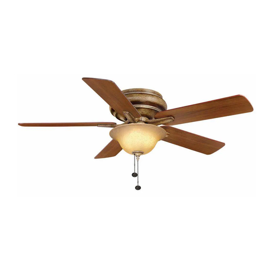
52” Bay Island Thank you for purchasing our ceiling fan. This product has been manufactured with the highest standards of safety and quality. Ceiling Fan by Hampton Bay Date Purchased Table of Contents Store Purchased Safety Rules ....1 104-478 UL Model No. -
Page 4: Safety Rules
Safety Rules - Read and Save These Instructions To reduce the risk of electric shock, insure electricity has been turned off After making electrical connections, spliced conductors should be turned at the circuit breaker or fuse box before beginning. upward and pushed carefully up into outlet box. The wires should be spread apart with the grounded conductor and the equipment-grounding All wiring must be in accordance with the National Electrical Code conductor on one side of the outlet box and ungrounded conductor on the... -
Page 5: Unpacking Your Fan
Unpacking Your Fan Unpack your fan and check the contents. You should have the following items: Set of blades (5) Mounting plate Blade Attachment Hardware 3/16"×7.5mm Screws (16PCs.) Mounting bracket Light kit assembly Fan motor assembly Glass shade Electrical Hardware Motor housing 40 Watt candelabra bulbs (3) Plastic Wire Nuts (3PCs.) -
Page 6: Installing Your Fan
Installing Your Fan Tools Required Figures 1 and 2 are examples of different ways to mount the outlet box. Phillips screwdriver, straight slot screwdriver, adjustable wrench, step ladder, and wire cutters. Outlet Box Mounting Options Outlet Box If there isn't an existing UL listed mounting box, then read the following instructions. -
Page 7: Hanging The Fan
(available at your Hampton Bay Retailer, the REMEMBER to disconnect the power. wire color out of wall control may vary, see wall control's installation manual for correct If you feel you do not have enough electrical wire connections.) - Page 8 SUPPLY CIRCUIT SUPPLY CIRCUIT SUPPLY CIRCUIT Ground Ground Ground Conductor Conductor Conductor Outlet Box Outlet Box Outlet Box Green Green Green Ground Ground Ground Lead Lead Lead Ground to Ground to Ground to Downrod Downrod Downrod Figure 6 Figure 7 Figure 8...
-
Page 9: Attaching The Fan Blades
WARNING Finishing the Fan TO REDUCE THE RISK OF PERSONAL INJURY, DO Installation NOT BEND THE BLADE HOLDERS WHILE INSTALLING, BALANCING THE BLADES, OR CLEANING THE FAN. DO NO INSERT FOREIGN Move fan into position over the four mounting OBJECTS BETWEEN ROTATING FAN BLADES. Studs studs and secure with the provided washers and nuts. -
Page 10: Blade Balancing
Blade Balancing Attaching the Mounting Plate The following procedure should correct most fan Touching Ceiling wobble. Check after each step. Remove the 1 of 3 screws from the mounting Check that all blade and blade holder screws ring and loosen the other 2 screws. (Do not are secure. -
Page 11: Installing The Light Kit
NOTE Installing the Light Kit LIGHT BULBS HAVE NO WARRANTY; CAN BE PURCHASED AT ANY HOME DEPOT STORE. CAUTION NOTE BEFORE STARTING INSTALLATION, DISCONNECT MAKE SURE TO LEAVE ENOUGH SPACE Fan without Light Kit THE POWER BY TURNING OFF THE CIRCUIT BETWEEN THE FAN PULL CHAIN AND THE BREAKER OR REMOVING THE FUSE AT FUSE BULBS SO THE CHAIN DOESN'T RUB AGAINST... -
Page 12: Operating Your Fan
Operating Your Fan NOTE Warm weather - (Counter-Clockwise direction) A downward air flow creates a cooling effect as WAIT FOR FAN TO STOP BEFORE REVERSING THE DIRECTION OF THE BLADE ROTATION. shown in Figure 16. This allows you to set your air conditioner on a higher setting without affecting your comfort. -
Page 13: Care Of Your Fan
MAKE SURE THE POWER IS OFF AT THE ELECTRICAL PANEL BOX Bay Ceiling Fan, please write to: BEFORE YOU ATTEMPY ANY REPAIRS. REFER TO THE SECTION, “MAKING ELECTRICAL CONNECTIONS”. THE HAMPTON BAY FAN & LIGHTING CO. P. O. Box 395 Norco, CA 92860 Call toll free 1-800-527-0998... -
Page 14: Specifications
Specifications FAN SIZE SPEED VOLTS AMPS WATTS N.W. G.W. C.F. 0.28 1808 9.98 kgs 11.52 kgs 52” MED. 0.45 3455 2.33’ (22.02 lbs) (25.41 lbs) 0.61 5302 HIGH These are approximate measures. They do not include Amps and Wattage used by the light kit . Distributed by Home Depot U.S.A., Inc. -
Page 15: Warranty Information
Lifetime Limited Warranty (lifetime warranty on motor) The retailer warrants the fan motor to be free from defects in workmanship and material present at time of You must present a copy of the original purchase receipt to obtain warranty shipment from the factory for a period of lifetime after the date of purchase by the original purchaser. The service.
Need help?
Do you have a question about the Bay Island and is the answer not in the manual?
Questions and answers