
Related Manuals for BK Precision 1601


Summary of Contents for BK Precision 1601
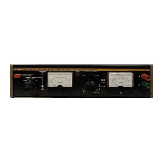
- Page 1 INSTRUCTION MANUAL B & K-PRECISION MODEL 1601 SOLID STATE REGULATED DC POWER SUPPLY D Y N A S C A N CORPORATION 6460 West Cortland Street Chicago, Illinois 60635...
-
Page 2: Table Of Contents
CONTENTS Page SPECIFICATIONS ........... FEATURES . -
Page 3: Specifications
SPECIFICATIONS Maximum 0.1%. 0.02% typ- LINE REGULATION O-SO VDC, continuously var- OUTPUT VOLTAGE ical, at output Voltage of 50 iable. Two ranges, 0-25 and VDC and output current of 2 O-50 VDC. amps from 105-125 VAC. O-2 amperes. Four ranges: OUTPUT CURRENT 5 millivolts peak-to-peak RIPPLE... -
Page 4: Introduction
INTRODUCTION Technicians The B & K Precision Model 1601 Regulated DC -Service Powering equipment or indi- Power Supply is a versatile, laboratory quality in- vidual circuits during testing strument which provides regulated dc voltage and and trouble-shooting in the current outputs of 0 to 50 volts and 0 to 2 amperes service shop. -
Page 5: Operating Instructions
Earth and chassis ground and prevents LEVEL control 13 from increasing the terminal. voltage above approximately Positive polarity Output ter- 9 + terminal 25 volts. minal. Turns off power supply at 13 LEVEL control Negative polarity output extreme counterclockwise ro- 10 - terminal terminal. -
Page 6: Applications
input which results in a surge current To reset the power supply, press and release the set/reset button 4 . If the overload when power is intially applied. When powering such equipment, the overload condition was intermittent, this action will may activate when the STBY-DC ON switch restore operation. -
Page 7: Servicing Vehicular Electronics Equipment
the power supply is not normally used nor required AM, AM/FM and AM/FM/Stereo automobile in this application. Using separate test lead colors, receivers such as red and black, reduces the chance of acci- *Tape players dental polarity connection. Set the current Citizen’s band transceivers reverse limit to the maximum input current specification of... - Page 8 If there is any doubt that the chassis m a y n o t b e ure 2 shows a typical example. The power supply common with the negative polarity, use a se- offers overload protection; therefore, any fuse in the ground connection from the (*l terminal equipment’s power cable is not required during equipment chassis.
-
Page 9: Servicing Plug-In Modules
quired for bench testing modules. Figure 5 shows a be determined with audio output: otherwise, the typical test set-up. Connect the (+) and (-) outputs overload circuit will be activated upon reception of of the power supply to the (+) and (-) power ter- audio. -
Page 10: Using The Power Supply Asa Battery Charger
SUPPLY (15 V) EQUIPMENT BEING POWERED POWER SUPPLY NO. 2 (3 V) NO. 2 (10 V) POWER NO. 1 POWER POWER NO. 2 NO. 2 Figure 6. Using Two Power Supplies for Two Output Voltages (Typical Examples1 USING THE POWER SUPPLY A BATTERY CHARGER POWER SUPPLY #l The power supply can be used as a battery... -
Page 11: Electronics Design Engineering
Use of the instrument in an engineering laboratory erated and vehicular equipment, while its use for is very similar to that previously described for serv- testing subassemblies is very similar to that de- icing electronics equipment and modules, except scribed for servicing modules. that lower currents may be prevalent when power- This power supply is particularly well suited for ing single stage experimental circuits. -
Page 12: Circuit Description
CIRCU U IT DESCRIPTION The unregulated B+ output level is pre-regulated GENERAL in coarse steps. As the LEVEL control is rotated The power supply converts a 117 VAC input to a clockwise from zero to maximum, the unregulated highly regulated and filtered dc output that is fully B+ voltage changes from its lowest to its highest adjustable from 0 to 50 volts and 0 to 2 amperes. - Page 13 volt). The voltage developed across the current The control Power winding of Tl. diodes D9 and sensing resistor is applied as the non-inverting input DlO, and filter capacitors Cl0 and C11 form the V+ (pin 2) to comparator ICI. and V- voltage source. These power source Cir- The inverting input at pin 3 of comparator ICl is cuits provide + 15 and -15 volts respectively.
-
Page 14: Maintenance
MAINTENANCE AND CALIBRATION WARNING - THE FOLLOWING INSTRUCTIONS ARE FOR USE BY QUALIFIED PERSONNEL ONLY. TO AVOID ELECTRICAL SHOCK, DO NOT PERFORM ANY SERVICING OTHER THAN THAT CONTAINED IN THE OPER- ATING INSTRUCTIONS UNLESS YOU ARE QUALIFIED TO DO SO. 5OV CAL (R30) This power supply is built to provide long, trouble-free service and does not require periodic...
Need help?
Do you have a question about the 1601 and is the answer not in the manual?
Questions and answers