Table of Contents
Advertisement
Advertisement
Table of Contents

Related Manuals for BK Precision 1686A


Summary of Contents for BK Precision 1686A
- Page 1 INSTRUCTION MANUAL MODEL 1686A 3 to 14 VOLT DC POWER SUPPLY...
-
Page 2: Test Instrument Safety
TEST INSTRUMENT SAFETY WARNING Normal use of test equipment exposes you to a certain amount of danger from electrical shock because testing must sometimes be performed where exposed high voltage is present. An electrical shock causing 10 milliamps of current to pass through the hear t will stop most human heartbeats. -
Page 3: Dc Power Supply
Instruction Manual MODEL 1686A 3 to 14 VOLT DC POWER SUPPLY 22820 Savi Ranch Parkway Yorba Linda, California 92887... -
Page 4: Table Of Contents
TABLE OF CONTENTS page page TEST INSTRUMENT SAFETY........ inside front cover MAINTENANCE................14 Fuse Replacement................14 INTRODUCTION.................5 Line Voltage Conversion.............14 Adjustments.................14 SPECIFICATIONS................6 Case Disassembly................14 Voltage and V Meter Adjustments..........15 CONTROLS AND INDICATORS............7 Current and A Meter Adjustments..........15 Instrument Repair Service............16 OPERATING INSTRUCTIONS............9 Safety Precautions................9 SERVICE INFORMATION............ -
Page 5: Introduction
INTRODUCTION The B+K Precision Model 1686 is a high quality 3 to 14 Volt The power supply utilizes thermostatically controlled fan DC Power Supply primarily designed for bench powering of cooling for improved heat dissipation and reliability while automotive and marine electronic equipment. The Model 1686 keeping bulk and weight to a minimum. -
Page 6: Specifications
SPECIFICATIONS OUTPUT VOLTAGE Ammeter 3 to 14 VDC, ADJUSTABLE Range Accuracy 0 to 20A ± 7% F.S. OUTPUT CURRENT PROPORTIONAL TO OUTPUT VOLTAGE; AC Input 2.5A 115/230 VAC ±10%, 50/60Hz. 4.5A 7.5A POWER CONSUMPTION 10.0A 400 W 13.8V 12.0A 12.0A TEMPERATURE RANGE &... -
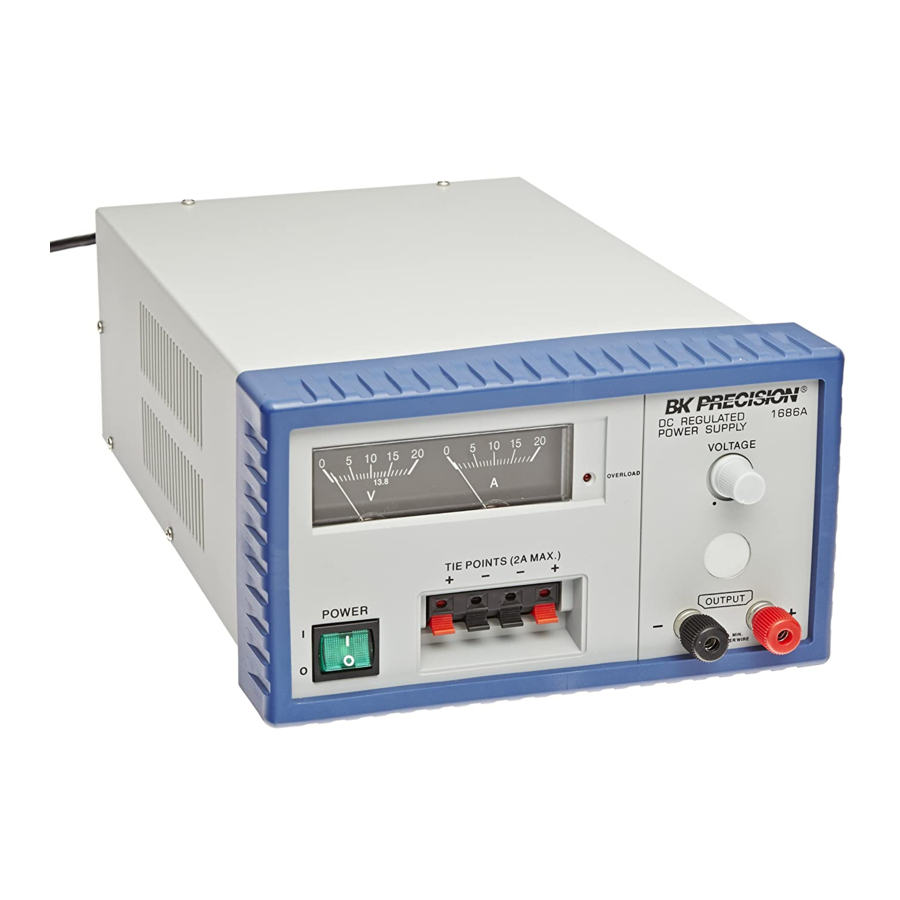
Page 7: Controls And Indicators
CONTROLS AND INDICATORS 7. OUTPUT “+” Terminal (Red). Positive polarity output 1. POWER Switch. Turns power supply on and off. Power on indicated by pilot lamp above switch. terminal. 8. OUTPUT “–” Terminal (Black). Negative polarity output terminal. 2. Power ON light. Lights when power is turned on. 3. - Page 8 CONTROLS AND INDICATORS Figure 2. Rear Panel Figure 1. Front Panel Controls and Indicators, Model 1686A.
-
Page 9: Operating Instructions
OPERATING INSTRUCTIONS SAFETY PRECAUTIONS EQUIPMENT PROTECTION PRECAUTIONS WARNING CAUTION The following precautions must be observed to The following precautions will help avoid help prevent electric shock. damage to the power supply. 1. Avoid using the power supply in ambient temperatures 1. -
Page 10: Considerations
OPERATING INSTRUCTIONS NOTE 3. The clip type TIE POINT terminals can be used to attach equipment requiring a maximum of 2 amps. Be sure to Use solid copper hook-up wire with a observe polarity when connecting equipment. minimum diameter of 12 AWG. Using 4. -
Page 11: Current Limiting
OPERATING INSTRUCTIONS CURRENT LIMITING The voltage is controlled by both VOLTAGE controls and is equal to the sum of the two V meter readings. Adjust voltage Overload (Foldback) current limiting gives protection against so that each power supply provides about half the total voltage. excessive overload and short circuit output. - Page 12 OPERATING INSTRUCTIONS Figure 4. Connecting Two Power Supplies in Series for a 6-to-28 Volt Output.
- Page 13 OPERATING INSTRUCTIONS Figure 5. Connecting Two Power Supplies in Parallel for 3-to-14 Volt Output at Double Amperage.
-
Page 14: Maintenance
MAINTENANCE WARNING 1. Make sure the power cord is unplugged. 2. Turn the unit over (bottom up) and reset the LINE The following instructions are for use by qualified personnel only. To avoid electrical VOLTAGE SELECT switch for the desired line voltage, shock, do not perform any servicing other 115V or 230V. -
Page 15: Voltage And V Meter Adjustments
MAINTENANCE 2. Remove the ten screws that hold the case top to the chassis and front bezel. 3. Pull the front bezel away from the chassis to access the calibration adjustments. VOLTAGE AND V METER ADJUSTMENTS 1. Connect the multimeter (set to 20 DCV Range) to measure the dc voltage across the power supply (+) and (–) OUTPUT terminals. -
Page 16: Instrument Repair Service
MAINTENANCE 3. Adjust Trimmer VR5 so that the meter pointer on the A INSTRUMENT REPAIR SERVICE meter lines up with the 10 amp mark. Because of the specialized skills and test equipment required 4. Remove the multimeter in series with the load, and reconnect for instrument repair and calibration, many customers prefer to it in parallel with the load to measure voltage (set to 20 DCV rely upon B+K Precision for this service. -
Page 17: Service Information
Service Information Warranty Service: Please return the product in the original packaging with proof of purchase to the address below. Clearly state in writing the performance problem and return any leads, probes, connectors and accessories that you are using with the device. Non-Warranty Service: Return the product in the original packaging to the address below. -
Page 18: Limited One-Year Warranty
Limited One-Year Warranty B&K Precision Corp. warrants to the original purchaser that its products and the component parts thereof, will be free from defects in workmanship and materials for a period of one year from date of purchase. B&K Precision Corp. will, without charge, repair or replace, at its option, defective product or component parts. Returned product must be accompanied by proof of the purchase date in the form of a sales receipt. - Page 19 TEST INSTRUMENT SAFETY (continued from inside front cover) 4. If possible, familiarize yourself with the equipment being tested and the location of its high voltage points. However, remember that high voltage may appear at unexpected points in defective equipment. 5. Use an insulated floor material or a large, insulated floor mat to stand on, and an insulated work surface on which to place equipment; and make certain such surfaces are not damp or wet.
- Page 20 B&K Precision Corporation 22820 Savi Ranch Parkway Yorba Linda, California 92887 www.bkprecision.com ©2014 B&K Precision Corporation 481-370-9-001 Printed in China V043014...
Need help?
Do you have a question about the 1686A and is the answer not in the manual?
Questions and answers