Enviro Bern Technical Manual
Hide thumbs
Also See for Bern:
- Technical manual (31 pages) ,
- Owner's manual (14 pages) ,
- Owner's manual (13 pages)
Table of Contents
Advertisement
Quick Links
SHERWOOD INDUSTRIES IS AN ENVIRONMENTALLY RESPONSIBLE COMPANY. THIS MANUAL IS PRINTED ON RECYCLED PAPER.
PLEASE KEEP THESE INSTRUCTIONS FOR FUTURE REFERENCE
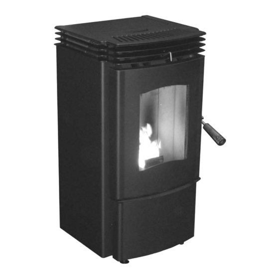
PELLET STOVE
Bern
TECHNICAL MANUAL
����
PLEASE READ THIS ENTIRE MANUAL BEFORE INSTALLATION AND USE
OF THIS PELLET BURNING ROOM HEATER. FAILURE TO FOLLOW THESE
INSTRUCTIONS COULD RESULT IN PROPERTY DAMAGE, BODILY INJURY
OR EVEN DEATH
Contact your building or fire officials about restrictions and installation
inspection requirements in your area.
50-1576
Advertisement
Table of Contents

Related Manuals for Enviro Bern


Summary of Contents for Enviro Bern
- Page 1 SHERWOOD INDUSTRIES IS AN ENVIRONMENTALLY RESPONSIBLE COMPANY. THIS MANUAL IS PRINTED ON RECYCLED PAPER. PLEASE KEEP THESE INSTRUCTIONS FOR FUTURE REFERENCE PELLET STOVE Bern TECHNICAL MANUAL ���� PLEASE READ THIS ENTIRE MANUAL BEFORE INSTALLATION AND USE OF THIS PELLET BURNING ROOM HEATER. FAILURE TO FOLLOW THESE...
-
Page 2: Table Of Contents
Table of Contents Safety Warnings & Recommendations....................3 Installation.............................6 Rating Label Location........................6 Deciding Where to Locate your Pellet Appliance................6 Removing Pellet Stove From Pallet.....................6 Dimensions & Specifications.......................7 Clearances to Combustibles.......................8 Alcove Clearances:........................8 Vent Termination Requirements....................9 Exhaust Location........................10 Corner Through Wall Installation....................10 Horizontal Exhaust Through Wall Installation................11 Through Wall With Vertical Rise and Horizontal Termination Installation - Freestanding....12 Inside Vertical Installations......................13... -
Page 3: Safety Warnings & Recommendations
To prevent the possibility of a fire, ensure that the appliance is properly installed by adhering to the installation instructions. An ENVIRO dealer will be happy to assist you in obtaining information with regards to your local building codes and installation restrictions. - Page 4 GLASS: Do not abuse the glass by striking or slamming the door. Do not attempt to operate the stove with broken glass. The stove uses ceramic glass. Replacement glass must be purchased from an ENVIRO dealer. Do not attempt to open the door and clean the glass while the unit is in operation or if glass is hot.
- Page 5 Safety Warnings & Recommendations FRESH AIR: Outside Fresh Air connection is optional. Fresh Air must be connected to all units installed in “Air Tight Homes” or where required by local codes. Consider all large air moving devices when installing your unit and provide room air accordingly. NOTE: Extractor fans when operating in the same room or space as the appliance, may cause problems.
-
Page 6: Installation
Installation ATING ABEL OCATION The rating label is located on the back of the unit. ECIDING HERE TO OCATE YOUR ELLET PPLIANCE 1. Check clearances to combustibles. 2. Do not obtain combustion air from an attic, garage or any unventilated space. Combustion air may be obtained from a ventilated crawlspace. -
Page 7: Dimensions & Specifications
(393 mm) " " (481 mm) (455 mm) " (883 mm) " " (444 mm) (497 mm) Figure 2: Dimensions of Bern. Table 1: Bern Specifications. Classification Testing Standard Description Class I IP-20 EN14785:2006/EN13240:2001/A2:2004 Residential Wood Pellet Heater Voltage Current Frequency 220 - 240 V 2.0 - 2.2 Amps... -
Page 8: Clearances To Combustibles
100mm (4 inches) Adjacent wall to corner of unit 100mm (4 inches) Any combustible directly in front of the unit 800mm (311⁄2 inches) Figure 3: Bern Clearance to Combustibles. LCOVE LEARANCES ��� This unit may be installed in an alcove. Maintain �������... -
Page 9: Vent Termination Requirements
Installation ERMINATION EQUIREMENTS IT IS RECOMMENDED THAT YOUR PELLET STOVE BE INSTALLED BY AN AUTHORIZED DEALER/INSTALLER. Table 2: Use in conjunction with Figure 5 for allowable exterior vent termination locations. Letter Minimum Clearance Description 61cm (24 in) Above grass, top of plants, wood, or any other combustible materials. Beside/below any door or window that may be opened. -
Page 10: Exhaust Location
103⁄4” (273 mm) Side of unit to center of flue 83⁄4” (222 mm) [at center of unit] " (273mm) " (222mm) Figure 6: Bern Inlet and Outlet Location. ORNER HROUGH NSTALLATION 4" (8 cm) Wall thimble manufactured by pellet vent manufacturer. -
Page 11: Horizontal Exhaust Through Wall Installation
Installation ORIZONTAL XHAUST HROUGH NSTALLATION Vent installation: install vent at clearances specified by the vent manufacturer. A chimney connector shall not pass through an attic or roof space, closet or similar concealed spaces, or a floor, or ceiling. Where passage through a wall or partition of combustible construction is desired, the installation must conform with all local regulations, including those referring to regional, national or European Standards. -
Page 12: Through Wall With Vertical Rise And Horizontal Termination Installation - Freestanding
Installation 11. Install a vertical pipe, or if all requirements for direct venting are met, install vent termination. The stainless steel cap termination manufactured by the vent manufacturer is recommended. However, when the vent terminates several feet above ground level and there are no trees, plants, etc. within several feet, a 45°... -
Page 13: Inside Vertical Installations
Installation NSIDE ERTICAL NSTALLATIONS 1. Choose a stove location that is ideal. See the section “D .” ECIDING HERE TO OCATE YOUR ELLET PPLIANCE 2. Place a non-combustible hearth pad where necessary. 3. Place the unit on the hearth pad (if installed on a carpeted surface) and ����... -
Page 14: Hearth Mount Installation
Installation Rain cap Flashing 24" (61 cm) 3" (7.5 cm) Clearance 4" (10 cm) Support bracket Tee with cleanout ���� ��� ����� ����� �� �������� Type "L" vent �������� �� ����� �� ��������� ����� ����� Figure 13: Outside Vertical Installation. EARTH OUNT NSTALLATION... - Page 15 Installation Rain cap Storm collar Seal plate (cover plate) Existing masonry flue Vent pipe (single wall stainless flex pipe or solid PL vent) Flexible vent connector (use this 5 foot [152cm] section of pipe to vent past fireplace damper or small shelf) Fireplace damper location Clean out tee...
-
Page 16: Exterior Mounted Exhaust Blower
XHAUST LOWER The Bern can be equipped with an externally mounted exhaust blower. This optional kit includes all components necessary to install the exhaust blower on any vertical wall surface. Choose a location for your stove that meets the requirements... -
Page 17: Typical Through Wall With Exterior Blower Kit Installation - Horizontal Termination
Installation YPICAL HROUGH XTERIOR LOWER NSTALLATION ORIZONTAL ERMINATION 90° Elbow 45°Elbow with Rodent screen or stainless steel termination hood 2ft (610mm) Riser Pipe Adaptor Exterior Blower and Housing Electrical Cable Figure 19: Through Wall Installation with Exterior Blower Kit. NOTE: Ensure that all interior vent connections are sealed by placing a small bead of high temperature silicone around each chimney connection. -
Page 18: Typical Through Wall With Exterior Blower Kit Installation - Vertical Termination
Installation YPICAL HROUGH XTERIOR LOWER NSTALLATION ERTICAL ERMINATION Follow the previous pages for through wall installations. Ensure that vent pipe is properly secured to wall using wall straps. Maintain clearances to combustibles on vent pipe as well as unit. Roof Sheathing Rain Cap Roof Flashing Roof Rafters... -
Page 19: Thermostat Installation
Installation HERMOSTAT NSTALLATION 1. Install the wall thermostat (12 or 24 Volt rated) in a location that is not to close too the unit but will effectively heat the desired area. 2. Connect the Thermostat or Timer using an 2 x 18 gauge wire from the unit to the thermostat. If the unit has been placed in the HI / LOW mode, the unit will be taken to a low or idle setting when the thermostat is not calling for heat. -
Page 20: Slider/Damper Set-Up
Installation LIDER AMPER This is used to regulate the airflow through the pellet stove. The slider damper should be set by a trained technician using magnehelic. The slider damper is located behind the left side panel. To open the left side panel, undo the one screw located in the upper front corner of the cabinet side between the louvers. -
Page 21: Optional Panel Kit
Installation PTIONAL ANEL This kit must be installed before the unit is started. Tools Required: ●T-20 screwdriver Kit Components: Quantity Description Panel Left Cab Panel Right Cab Hopper Lid #8 T-20 screws (3⁄8” long) Figure 27: Screws above door top corner. Hopper Bracket Bushing 1⁄4”... -
Page 22: Optional Fan Kit
Installation Installing Hopper Lid: 1. Attach the hopper brackets to the back of the unit with a screw in each top holes of the brackets (#1 in Figure 30). Do not tighten these screws until all six (6) screws are in place. 2. -
Page 23: Troubleshooting
Troubleshooting DO NOT: ● Service the stove with wet hands. The stove is an electrical appliance, which may pose a shock hazard if handled improperly. Only qualified technicians should deal with possible internal electrical failures. ● Do not remove from the firebox any screws without penetrating oil lubrication. WHAT TO DO IF: 1. - Page 24 Troubleshooting üPoor Quality Fuel – Insufficient energy in the fuel to produce enough heat to keep the stove burning or operational. üExhaust Temperature Sensor failure. – Bypass sensor located on Exhaust Blower if stove now operates properly, the unit may require cleaning or a new sensor. Contact your local dealer for service. üCheck the fuse on the circuit board.
- Page 25 Troubleshooting 7. The convection blower will not function normally. üClean all grill openings at the back and below unit . üPress the fan button; does the fan come on? Press again to verify that the blower turns on; if, not contact your local dealer for service.
-
Page 26: Wiring Diagram
Wiring Diagram Armor Cable Supplied Grey Optional Exterior Vacuum Exhaust Blower Grey Switch Black White White Combustion Blue Brown Blower Exhaust Temperature Sensor Power Cord Brown Ground Black 115V 115V White Black Black White 220V 220V Brown Blue Thermostat Common 5 Amp Fuse Ignitor... -
Page 27: Parts List
Parts List Reference # Description Part # 120°F (49°C) Ceramic Fan Temperature Sensor EC-001 Window Channel Tape - 1.8m (6ft) EC-058 Auger Motor - 220V EF-001-220V High Limit Temp Sensor 200°F (93°C) Manual Reset EF-016 Vacuum Switch - 220V EF-017-220V Combustion Blower Mounting Gasket EF-011 Combustion Blower Housing Gasket... - Page 28 Cabinet Side Right - SS 50-1480 Control Panel Decal 50-1482 Backdraft Flap Gasket 50-1520 Circuit Board with Thermostat Switch 2sec On Time 230V 50-1521 Gloves 50-1525 Ignitor Mounting Braket 50-1542 Bern International Owner’s Manual 50-1575 Bern International Technical Manual 50-1576 EMI Filter 50-1584...
-
Page 29: Parts Diagram - Components
Parts Diagram - Components �� �� � �� �� �� �� � �� �� � �� � � � � �� �� �� �� Bern - Components May 2007... -
Page 30: Parts Diagram - Steel
Parts Diagram - Steel... -
Page 31: Installation Data Sheet
_________________________________________ _________________________________________ _________________________________________ PHONE:___________________________________ WARRANTY: If you have any concerns with your unit please contact the dealer where you purchased the stove. MANUFACTURED BY: SHERWOOD INDUSTRIES LTD. 6782 OLDFIELD RD. SAANICHTON, BC, CANADA V8M 2A3 www.enviro.com September 10, 2007 C-11439...
Need help?
Do you have a question about the Bern and is the answer not in the manual?
Questions and answers