Advertisement
Table of Contents
- 1 Mounting Locations
- 2 Mounting Considerations for Single Ended Beam Detectors
- 3 Installation / Alignment
- 4 Pre-Alignment Checklist
- 5 Step 2. Fine Adjustment
- 6 Step 4. Final Verification
- 7 Sensitivity Selection
- 8 Maintenance
- 9 Appendix I. Operation Modes and Troubleshooting Guide
- 10 Appendix II. Detector Drilling Template
- 11 Appendix III. Reflector Drilling Template
- Download this manual
INSTALLATION AND MAINTENANCE INSTRUCTIONS
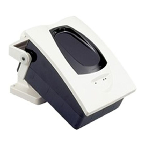
FSB-200, FSB-200S
Single-ended Reflected Type
Projected Beam Smoke Detector
Specifications
General
Range:
Sensitivity:
Spacing:
Response Time:
Trouble Conditions:
Test/Reset Features:
Indicators:
Style 7 Operation:
Environmental
Temperature:
Humidity:
Mechanical
Shipping Weight:
Shipping Size:
Mounting:
Wiring:
Plug-in Terminal Blocks (12 to 22AWG)
Adjustment Angle:
Paintable Trim Ring:
N200-25-00
16 to 230 Feet (5 to 70m)
230 to 328 Feet (70 to 100m) using optional accessory BEAMLRK
25% to 50% Total Obscuration in 6 levels
Level 1 = 25%
Level 2 = 30%
Level 3 = 40%
Level 4 = 50%
Level 5 = 30% to 50% (Acclimate)
Level 6 = 40% to 50% (Acclimate)
30 to 60 Feet (9.1 to 18.3m)
Alarm: 20 seconds typical
Trouble: 30 seconds typical
Beam Blockage (96% or More Obscuration)
Improper Initial Alignment
Self-compensation limit reached (service needed)
In Alignment mode
Integral Sensitivity Test Filter (FSB-200S only, requires additional external power supply)
Sensitivity Filter (Incremental scale on reflector)
Local Alarm Test Switch
Local Alarm Reset Switch
Remote Test and Reset Switch Capability
(compatible with RTS451/RTS451KEY)
Alarm:
Trouble:
Remote Output, Local LED (yellow)
Normal Operation:
Alignment Aids: Optical Gunsight (coarse adjustment)
Sensitivity:
On-board isolators provide style 7 operation.
(may be disabled via shunts on circuit board)
–22°F to 131°F (–30°C to 55°C)
Note: for applications below 32°F (0°C) see Special Applications section of this manual.
10% to 93% RH Noncondensing
3.9 lbs. (1.77 kg)
15" × 10.5" × 6.5" (381mm × 267mm × 165mm)
Wall only without optional accessories
±10° Horizontal and Vertical
May be painted using enamel or acrylic type paints
Remote Output, Local LED (red)
Blink Pattern Indicates Trouble Diagnostics
Local LED (flashing green with communication)
00 to 99 Digital Display (fine adjustment)
Digital Display Readout in Percent Obscuration
1
12 Clintonville Rd.
Northford, CT 06472-1653
Phone: 203/484-7161
I56-2424-04R
Advertisement
Table of Contents

Related Manuals for System Sensor FSB-200


Summary of Contents for System Sensor FSB-200
- Page 1 INSTALLATION AND MAINTENANCE INSTRUCTIONS FSB-200, FSB-200S Single-ended Reflected Type 12 Clintonville Rd. Northford, CT 06472-1653 Projected Beam Smoke Detector Phone: 203/484-7161 Specifications General Range: 16 to 230 Feet (5 to 70m) 230 to 328 Feet (70 to 100m) using optional accessory BEAMLRK...
- Page 2 Note: Output current is limited by 2.2Kohm resistor General Description Special Applications Model FSB-200/FSB-200S is a long range projected beam Due to the inherent capabilities of projected type beam smoke detector designed to provide open area protection. It detectors they are often installed in locations where spot- is to be used with UL-listed compatible control panels only.
- Page 3 Description Quantity The BEAMLRK allows System Sensor reflected beam detec- Transmitter/Receiver Unit ....1 tors to be installed at separations between 230 and 328 feet Paintable Trim Ring .
- Page 4 Figure 2. Spacing for smooth ceiling (top view): Some fire codes specify spacing on a given center-to-center distance between detectors under ideal conditions. This spacing is based on rooms with smooth ceilings and no 1/2 S Maximum physical obstructions between the contents being protected Tx/Rx Reflector and the detectors.
-
Page 5: Mounting Locations
Figure 4. Sloped ceiling (peaked type): the supplied drilling template (see Appendix II). The detec- tor base has 4 primary mounting keyholes, one in each Mount Detector Anywhere in This Area corner of the base. All four hole locations should be used to provide a secure mounting. -
Page 6: Mounting Considerations For Single Ended Beam Detectors
Figure 5b. Reflector Mounting Guidelines between the detector and the reflector, (A minimum of 10° off perpendicular should be considered), and make certain 10ϒ maximum that the glass is smooth, clear and mounted securely. The complete reflector blockage test can be used to determine if optical line of sight the installation is acceptable. - Page 7 COMMUNICATION LINE TO NEXT electrical ratings. PREVIOUS DEVICE 32 VDC MAX. DEVICE TWISTED PAIR IS RECOMMENDED. C0335-00 Figure 8. Wiring Diagram (RTS451) FSB-200/FSB-200S T1-1 Power In + Power Out + T1-3 Pin 1 T1-2 Power In – Power Out – T1-4...
-
Page 8: Installation / Alignment
3. Once the reflector has been located, begin to adjust both The alignment of the FSB-200/FSB-200S is divided into four the horizontal and vertical alignment knobs so that the steps: coarse alignment, fine adjustment, final gain adjust- reflector becomes centered in the alignment mirror. -
Page 9: Step 4. Final Verification
NOTE: The housing contains a gasket seal that protects at a time going back and forth between them until a peak value is indicated. If a value of 90 is achieved, the the detector circuitry from corrosion and moisture detector will re-adjust the electronic gain once again. sources. -
Page 10: Sensitivity Selection
Figure 10. Switch Locations Figure 12. Coarse Alignment Procedure ALIGNMENT SENSITIVITY TEST REFLECTOR RESET C0265-00 Figure 13. Housing Screw Locations STYLE 7 ISOLATOR SHUNTS (SHOWN DISABLED) C0263-00 Figure 11. Alignment Adjustment Locations ALIGNMENT MIRROR ALIGNMENT GUNSIGHT ALIGNMENT POSITION SCREW SCREW INDICATOR LOCATIONS LOCATIONS... - Page 11 To change the Detectors must be tested after installation and following sensitivity continue to depress the sensitivity switch until periodic maintenance. The sensitivity of the FSB-200/FSB- the desired setting is achieved. The digital display will turn 200S may be tested as follows: off automatically if no further switch presses occur.
- Page 12 4. The detector can be reset with the reset switch on the detector unit or remote reset. NOTE: For the FSB-200 this test does not satisfy the requirements of NFPA72 for periodic maintenance 5. Notify the proper authorities that the system is back on and sensitivity verification of beam type detectors.
-
Page 13: Maintenance
cedure. If the detector still fails the test it should be 2. Carefully clean the reflector. A damp soft cloth with a returned for repair. mild soap may be used. Avoid products with solvents or ammonia. NOTE: For the FSB-200S, the external power supply must be connected for the test switch to work. -
Page 14: Appendix I. Operation Modes And Troubleshooting Guide
Appendix I. Operation Modes and Troubleshooting Guide Blinks output by Yellow LED and Remote Trouble Output once the device has passed a local remote test: Percent the Number detector has of blinks drifted output <10% None <20% <30% <40% <50% <60% <70% <80%... -
Page 15: Appendix Ii. Detector Drilling Template
Appendix II. Detector Drilling Template 6.190″ 4.345″ Scale = 1:1 N200-25-00 I56-2424-04R... - Page 16 N200-25-00 I56-2424-04R...
-
Page 17: Appendix Iii. Reflector Drilling Template
Appendix III. Reflector Drilling Template 5.512″ (140mm) 8.465″ (215mm) Scale = 1:1 N200-25-00 I56-2424-04R... - Page 18 This equipment generates, uses, and can radiate radio interference at his own expense. N200-25-00 I56-2424-04R ©2004 System Sensor...
Need help?
Do you have a question about the FSB-200 and is the answer not in the manual?
Questions and answers