Advertisement
Quick Links
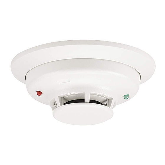
INSTALLATION AND MAINTENANCE INSTRUCTIONS
Series
Photoelectric Smoke Detector
Models:
2W-B, 2WT-B, 4W-B, 4WT-B
ELECTRICAL SPECIFICATIONS
System Voltage –Nominal:
Min.:
Max.:
Max. Ripple Voltage:
Max. Standby Current:
Peak Standby Current:
Max. Alarm Current:
(For 2W-B and 2WT-B, panel must limit current)
Alarm Contact Ratings:
Alarm Reset Time:
Max. Start-up Capacitance:
Latching Alarm: Reset by momentary power interruption
Maximum Initial
Start-up Time:
Alarm Verification*
Start-up Time:
*Assumes the panel's alarm verification reset time is 10 seconds or less. Should the alarm verification reset exceed 10 seconds, use the maximum initial start-up time.
PHYSICAL SPECIFICATIONS
Heat Sensor (Model 2WT-B and 4WT-B):
Freeze Trouble (Model 2WT-B and 4WT-B):
Operating Temperature Range:
2W-B and 4W-B:
2WT-B and 4WT-B:
Operating Humidity Range:
Storage Temperature Range:
Diameter (including base):
Height (including base):
Weight:
BEFORE INSTALLING
Please read thoroughly System Sensor's Applications Guide for System Smoke
Detectors (SPAG91), which provides detailed information on detector spacing,
placement, zoning, wiring, and special applications. This manual is available
online at www.systemsensor.com. s
NOTICE: This manual shall be left with the owner/user of this equipment.
IMPORTANT: This detector must be tested and maintained regularly following
NFPA 72 requirements. At a minimum, cleaning should be performed annually.
GENERAL DESCRIPTION
Models 2W-B and 2WT-B are 2-wire photoelectric smoke detectors; models
4W-B and 4WT-B are 4-wire photoelectric smoke detectors. All models in-
corporate a state-of-the-art optical sensing chamber and an advanced micro-
processor. The microprocessor allows the detector to automatically adjust its
sensitivity back to the factory setting when it becomes more sensitive due to
contaminants settling in its chamber. In order for this feature to work prop-
erly, the chamber must never be opened while power is applied to the smoke
detector. This includes cleaning, maintenance or screen replacement. Should
it become necessary, the screen/sensing chamber is field replaceable. Mod-
els 2WT-B and 4WT-B also feature a restorable, built-in, fixed temperature
(135°F) thermal detector and are also capable of sensing a freeze condition if
the temperature is below 41°F.
All i
3
Series detectors are designed to provide open area protection. Two-wire
models must be used with compatible UL Listed panels only.
When used with an i
3
Series compatible control panel or the i
MOD2 module (refer to installation manual D500-46-00), the 2W-B and 2WT-B
are capable of generating a "maintenance needed" signal. The 2W-MOD2 can
indicate a need for cleaning, replacement, or a freeze condition (2WT-B only)
at the control panel or module.
Installation of the 2W-B, 2WT-B, 4W-B, and 4WT-B detectors is simplified by
the use of a mounting base that may be pre-wired to the system, allowing the
2-WIRE
4-WIRE
12/24
12/24 Volts Non-polarized
8.5
8.5 Volts
35
35 Volts
30
30 % peak to peak of applied voltage
50
50 µA average
100
— µA
130
20 mA 12 Volt Systems
130
23 mA 24 Volt Systems
—
0.5 Amp @ 30 V AC/DC
0.3
0.3 sec
0.1
— µF
45
15 sec
15
15 sec
135°F (57.2°C)
41°F (5°C)
32 to 120°F (0 to 49°C)
32 to 100°F (0 to 37.8°C)
0 to 95% RH non-condensing
–4 to 158°F (–20 to 70°C)
5.3 inches
2.0 inches
6.3 oz.
detector to be easily installed or removed. The mounting base installation is
further simplified by the incorporation of features compatible with drywall
fasteners.
Two LEDs on the detector provide a local visual indication of the detector's status:
TABLE 1: DETECTOR LED MODES
Power-up
Normal (standby)
Out of sensitivity
Freeze Trouble
Alarm
After an initial power-up delay, the red and green LEDs will blink synchro-
nously once every ten seconds. It will take approximately 80 seconds for the
detector to finish the power-up cycle (see Table 2).
TABLE 2: POWER-UP SEQUENCE FOR LED STATUS INDICATION*
Condition
Initial LED Status Indication
Initial LED Status Indication
(if excessive electrical noise is present)
*Refer to Electrical Specifications for start-up time in conjunction with panel
3
Series 2W-
alarm verification.
NOTE: If, during power-up, the detector determines there is excessive electri-
cal noise in the system such as those caused by improper grounding of the
system or the conduit, both LEDs will blink for up to 4 minutes before display-
ing detector status (see Table 2).
1
3825 Ohio Avenue, St. Charles, Illinois 60174
1-800-SENSOR2, FAX: 630-377-6495
www.systemsensor.com
Green LED
Red LED
Blink 10 sec
Blink 10 sec
Blink 5 sec
—
—
Blink 5 sec
—
Blink 10 sec
—
Solid
Duration
80 seconds
4 minutes
I56-1800-014
02-02
Advertisement

Subscribe to Our Youtube Channel
Related Manuals for System Sensor 4WT-B


Summary of Contents for System Sensor 4WT-B
- Page 1 LEDs will blink for up to 4 minutes before display- ing detector status (see Table 2). Installation of the 2W-B, 2WT-B, 4W-B, and 4WT-B detectors is simplified by the use of a mounting base that may be pre-wired to the system, allowing the...
- Page 2 For two-wire models 2W-B and 2WT-B, connect detectors only to compatible alarm control panels S0121-00 as identified by System Sensor’s compatibility chart. This chart contains the The i Series heads and bases are keyed so that a 2-wire head will only mount current list of detectors and UL Listed compatible control units.
- Page 3 “Green LED” indicator on the base. Wire the mounting base screw terminals per Figure 3a or Figure 3b, as C. DIRECT HEAT METHOD (MODELS 2WT-B AND 4WT-B ONLY) applicable. Using a 1000-1500 watt hair dryer, direct the heat toward either of the thermis- Place detector on the base and rotate clockwise.
- Page 4 Please refer to insert for the Limitations of Fire Alarm Systems THREE-YEAR LIMITED WARRANTY System Sensor warrants its enclosed smoke detector to be free from defects in materials Drive, Suite 700, El Paso TX 79936, USA. Please include a note describing the malfunc- and workmanship under normal use and service for a period of three years from date tion and suspected cause of failure.
Need help?
Do you have a question about the 4WT-B and is the answer not in the manual?
Questions and answers
How to reset/reboot the detector after it has alarmed and the red light is still lit? It alarmed due to a small amount of smoke from the kitchen.