Table of Contents
Advertisement
Available languages
Available languages
Quick Links
GENERAL
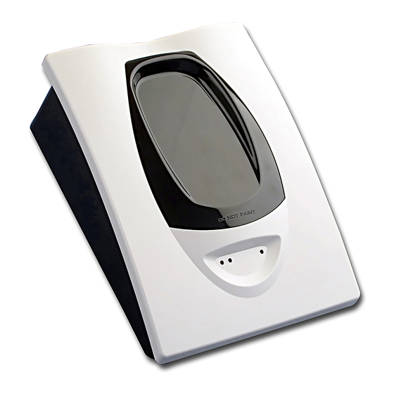
The model 6500RE is a conventional long range projected beam smoke
detector designed to provide open area protection.
combined transmitter/receiver unit and a reflector. Smoke entering the area
between the two components causes a reduction in the signal returned to
the receiver. When the obscuration reaches alarm thresholds, selected
at the transmitter/receiver unit, the detector generates an alarm signal.
Complete blockage of the beam causes a fault signal. Slow changes in
obscuration due to a build up of dirt or dust on the lens of the detector are
compensated for by a micro-controller that continuously monitors the signal
strength and periodically updates the alarm and fault thresholds. When the
self-compensation circuit reaches its limit, the detector generates a fault
signal, indicating the need for service. After local testing is complete, the
yellow LED will blink a pattern to indicate the level of drift compensation
employed during the test (see Blinks Output by Yellow LED table at back
of manual).
The model 6500RSE includes an integral servo controlled calibrated test
filter, which allows automatic remote alarm testing.
SPECIFICATIONS:
General
Range:
10 to 70m
70 to 100m using optional accessory 6500-LRK/BEAMLRK
Sensitivity:
EN54-12: 2015 Levels
Level 1 = 25% Obscuration(1.25dB)
Level 2 = 30% Obscuration (1.55dB)
Level 3 = 40% Obscuration (2.22dB)
Non EN54-12: 2015 Levels
Level 4 = 50% Obscuration (3.01dB)
Level 5 = 30% to 50% Adjusting (Acclimate Level 1)
Level 6 = 40% to 50% Adjusting (Acclimate Level 2)
Maximum angular misalignment:
Environmental
Temperature Range:
Humidity:
Mechanical
Dimensions (Without Faceplate):
Dimensions (With Faceplate):
Wiring:
Adjustment Angle:
Electrical
Voltage Range:
Avg. Standby Current:
Max. Alarm Current:
Max. Fault Current:
6500RSE Test Mode:
Relay Contact Ratings:
Remote Output (Alarm):
PARTS LIST
Description
Transmitter/Receiver Unit
Paintable Trim Ring
Reflector (6500REFL)
Plug in terminal blocks
Instruction Manual
Orange Alignment Assistance Label
Alarm 0 ohm Shunt
Alarm Limiting Resistor 470 ohm
Alarm Limiting Resistor 680 ohm
Alarm Limiting Resistor 1000 ohm
Schottky Diode
DB200-04-00
REFLECTED BEAM SMOKE DETECTOR
INSTALLATION AND MAINTENANCE INSTRUCTIONS
It consists of a
Detector: ± 0.5° Reflector: ± 10°
-30°C to 55°C
10% to 95% Relative Humidity
(Non-condensing)
229mm x 178mm x 84mm
253mm x 193mm x 84mm
0.3mm² to 3.2mm²
±10° Horizontal and Vertical
6500RE:
10.2 to 32 VDC
6500RSE:
15 to 32VDC
17mA at 24 VDC
38.5mA at 24VDC
8.5mA at 24 VDC
500mA peak
0.5A at 30 VDC
Voltage:
15 to 32VDC
dependant on supply
Current:
6mA to 15mA,
Limited by 2.2KΩ Resistor
Quantity
1
1
1
5
1
1
1
1
1
1
1
6500R(S)E
APPROVED ACCESSORIES
6500-LRK/BEAMLRK
Long Range Kit comprising three additional 20cm x 20cm reflectors, which
may be mounted in a square with the supplied reflector, permitting the
detector to be used for ranges from 70m to 100m.
6500-MMK/BEAMMMK
Multi-Mounting Kit allowing the 6500RE to be mounted to ceilings, or to
walls where the detector and reflector cannot be mounted within 10° of one
another. One kit mounts either the transmitter/receiver unit or reflector. If
the transmitter/receiver is mounted on the 6500-MMK/BEAMMMK, then the
6500-SMK/BEAMSMK must be used. Note that only a single 20cm x 20cm
reflector can be mounted using the MMKs: The 6500-LRK/BEAMLRK is
not compatible with the MMKs.
6500-SMK/BEAMSMK
Surface Mounting Kit for the transmitter receiver (also used in combination
with the MMK) to give an additional 43mm depth to assist surface mounting
and to permit side entry cabling.
RTS151KEY
Remote test and annunciator accessory that enables the detector to be
tested remotely, providing test and reset functions, it has a Red LED to
indicate alarm conditions (Note: Back-box, if required, needs to be ordered
separately - part number WM2348).
DETECTOR MOUNTING
Location
The 6500R(S)E must be located in accordance with local standards and
guidelines, for example BS5839 part 1. For general information, refer to
the application guide for projected beam smoke detectors available on
request from your supplier.
Mounting Position
Beam detectors require a very stable mounting surface for proper operation.
A surface that moves, shifts, vibrates, or warps over time may cause false
alarm or fault conditions. Initial selection of a proper mounting surface
will eliminate nuisance alarms and fault signals. Mount the detector on a
stable mounting surface such as brick, concrete, a sturdy load-bearing wall,
support column, structural beam, or other surface that is not expected to
experience vibration or movement over time. DO NOT MOUNT the beam
detector on corrugated metal walls, sheet metal walls, external building
sheathing, external siding, suspended ceilings, steel web trusses, rafters,
non-structural beam, joists, or other such surfaces. The reflector has a
much greater tolerance to movement than the transmitter/receiver, hence
in cases where only one stable mounting surface as defined above can be
used, the transmitter/receiver unit should be mounted to the stable surface.
See specifications for maximum permissible angular misalignment;
movement outside these limits may cause nuisance alarms and faults.
Mounting Considerations
•
There must be a permanent clear line of vision between the detector
and the reflector.
•
Reflective objects should be a minimum of 380mm from the line of
sight between the detector and reflector to avoid compromise of the
protected area by reflected light.
•
Direct sunlight or strong lights into the transmitter/receiver unit should
be avoided. There should be a minimum of 10° between the paths of
the light source and the detector beam.
•
Operation of the detector through panes of glass should be avoided if
possible. If it is necessary to pass though glass, the angle between the
beam and glass should be set a minimum of 10° off perpendicular, and
operation through multiple panes should be avoided.
Mounting
The transmitter/receiver unit may be mounted directly to the wall, with rear
cable entry. The detector base has four primary mounting holes, one in
each corner of the base. All four holes must be used to provide secure
mounting. In order to mount the detector to the wall, the outer cover must
be removed after unscrewing its four retaining screws.
1
I 56- 4446- 000
I56-4446-000
Advertisement
Table of Contents

Related Manuals for System Sensor 6500RE


Summary of Contents for System Sensor 6500RE
- Page 1 6500-MMK/BEAMMMK at the transmitter/receiver unit, the detector generates an alarm signal. Multi-Mounting Kit allowing the 6500RE to be mounted to ceilings, or to Complete blockage of the beam causes a fault signal. Slow changes in walls where the detector and reflector cannot be mounted within 10° of one obscuration due to a build up of dirt or dust on the lens of the detector are another.
- Page 2 10°. If this tolerance is not possible, then the MMK should be used, see MMK instructions for mounting details. 10° 10° Figure 3: Detector Terminal Connections ACCEPTABLE MOUNTING 6500RE / 6500RSE LOCATIONS FOR REFLECTOR REMOTE ALARM T2-1 RTS151/KEY OUTPUT...
-
Page 3: Alignment Procedure
To power. prevent unwanted alarms, disable the zone prior to applying power. The alignment of the 6500RE is divided into four steps: Coarse alignment, • Ensure power to the detector is “ON”. - Page 4 Note that the alignment gun site does not give an accurate alignment. It values. Any number is acceptable, provided it is the highest figure that is sufficient only as a starting point for the next step. On completion of the can be achieved after the final gain adjustment.
-
Page 5: Maintenance
Final Verification Detectors must be tested after installation and following periodic Use obscuration filters or reflector test card to initiate Fire and Fault signals maintenance. The sensitivity of the 6500RE may be tested as follows: MAINTENANCE Calibrated Test Filter Method... - Page 6 EN54-12: 2015 Optical Beam Smoke Detector Intended for use in fire detection and fire alarm systems in and around buildings Honeywell Products and Solutions Sàrl (Trading as System Sensor Europe) Zone d’activités La Pièce 16 CH-1180 ROLLE, Switzerland DB200-04-00 I56-4446-000...
- Page 7 Livello 3: 40% di oscuramento (2,22dB) Locazione Livelli non approvati EN54-12: 2015 Il sistema 6500RE deve essere montato in accordo con le linee guida e con Livello 4: 50% di oscuramento (3,01dB) le regolamentazioni locali. Per informazioni generali, fare riferimento alla Livello 5 (variabile 1): dal 30% al 50% variabile in funzione dell’ambiente...
- Page 8 1 2 3 4 1 2 3 4 utilizzare il kit MMK ( vedere le istruzioni del kit MMK per i dettagli). 10° 10° Figura 3: Connessione ai terminali del rivelatore 6500RE/6500RSE LOCAZIONE ACCETTABILE PER IL MONTAGGIO DEL RIFLETTORE REMOTE ALARM T2-1...
- Page 9 Assicurarsi che il rivelatore sia alimentato guasto o allarme. Per prevenire questo inconveniente, disabilitare la zona prima di applicare l’alimentazione. SPECCHIO PER L’allineamento del 6500RE comprende 4 fasi: pre-allineamento e L’ALLINEAMENTO allineamento grossolano, allineamento fine, regolazione del guadagno MIRINO PER INDICATORI e verifica finale.
- Page 10 L’allineamento effettuato con il mirino e lo specchio non dà un allineamento Nota: è possibile che il valore di 90 sul display non venga mai raggiunto. particolarmente accurato. E’ solo un punto di partenza per il passo Ogni volta che il valore 90 viene raggiunto viene automaticamente successivo.
-
Page 11: Manutenzione
SENSORE DI FUMO A RAGGIO OTTICO 6500RE: SOMMARIO DEL dell’ambiente dell’installazione. La sensibilità viene continuamente SET-UP aggiornata entro i limiti illustrati nel grafico 1 Allineamento: assicurarsi che il sensore sia alimentato L’oscuramento totale può... - Page 12 EN54-12: 2015 Optical Beam Smoke Detector Intended for use in fire detection and fire alarm systems in and around buildings Honeywell Products and Solutions Sàrl (Trading as System Sensor Europe) Zone d’activités La Pièce 16 CH-1180 ROLLE, Switzerland DB200-04-00 I56-4446-000...
-
Page 13: Especificaciones
ACCESORIOS APROBADOS GENERAL 6500-LRK/BEAMLRK El modelo 6500RE es un detector de humo convencional por rayo proyectado de largo alcance, diseñado para proteger áreas diáfanas. Kit de largo alcance que consta de tres reflectores adicionales de 20 cm x Consta de dos dispositivos: una unidad en la que se combinan transmisor 20 cm, lo que permite utilizar el detector para distancias entre los 70 y 100 m. - Page 14 MMK si desea más detalles. 10° 10° Figura 3: Conexiones de los terminales del detector UBICACIONES DE MONTAJE 6500RE / 6500RSE ACEPTABLES PARA EL REFLECTOR ALARMA REMOTA T2-1 RTS151/KEY Figura 2a: Instrucciones para el montaje del reflector SALIDA...
- Page 15 Para evitar alarmas no deseadas, anule la zona antes de aplicar alimentación. ESPEJO DE La alineación de 6500RE se divide en cuatro fases: alineación inicial, ALINEACIÓN ajuste fino, ajuste de ganancia final y verificación final. Es necesario INDICADOR DE LA ALINEACIÓN A...
- Page 16 Observe que el punto de mira no proporciona una alineación exacta. Nota: Puede que no sea posible alcanzar un número cercano a 90 en Únicamente sirve como punto de partida para el siguiente paso. Al finalizar la pantalla durante el último ajuste. Cada vez que se alcanza el número el proceso de ajuste fino, el punto de mira puede que parezca no estar 90, la ganancia se reduce, lo que dificulta, cada vez más, el llegar a centrado en el reflector.
-
Page 17: Mantenimiento
Pulsar el Botón de rearme. Los detectores se deben probar después de la instalación y someterse a El proceso finaliza cuando el Led verde parpadea. tareas de mantenimiento de forma periódica. La sensibilidad del 6500RE se Verificación final. puede probar de la siguiente manera: Utilizar los filtros de oscurecimiento o la hoja de prueba del reflector para activar las señales de Alarma y Avería. - Page 18 1293 20 6500R(S)E - DOP-LBP025 EN54-12: 2015 Detector de Humo por Rayo Honeywell Products and Solutions Sàrl (Trading as System Sensor Europe) Zone d’activités La Pièce 16 CH-1180 ROLLE, Switzerland DB200-04-00 I56-4446-000 Pittway Tecnologica S.r.l., Via Caboto 19/3, 34147 TRIESTE, Italy...
-
Page 19: Spezifikation
INSTALLATIONS- UND WARTUNGSANLEITUNG LINEARER RAUCHMELDER MIT PRISMEN-REFLEKTOR ALLGEMEIN VOM HERSTELLER ZUGELASSENES ZUBEHÖR Der Lineare Rauchmelder 6500RE ist ein Langstrecken-Melder in 6500-LRK/ BEAMLRK Grenzwerttechnik und wird zur Überwachung von offenen Bereichen Langstrecken-Zubehör, bestehen aus drei zusätzlichen Prismen-Reflektoren eingesetzt. Der Melder besteht aus einer Sender-/Empfänger-Einheit (20 cm x 20 cm) zur Vergrößerung der Überwachungsstrecke von 70 m auf... - Page 20 Winkel größer, ist zusätzlich der Befestigungssatz MMK erforderlich. Weiterführende Informationen zum Befestigungssatz MMK sind der Installationsanleitung zu entnehmen. 10° 10° Abbildung 3: Anschlussbelegung der Melderklemmleisten GEEIGNETER MONTAGEORT FÜR PRISMEN-REFLEKTOR 6500RE / 6500RSE Abbildung 2a: Richtlinien zur Montage des Prismen-Reflektors ALARM-AUSGANG T2-1 RTS151/KEY EXT.-ANZEIGE 10° MAXIMUM T2-2...
- Page 21 Stellen Sie sicher, dass die Betriebsspannung des Melders Meldergruppe ab, bevor die Versorgungsspannung angelegt wird. “eingeschaltet” ist. Die Ausrichtung des Melders 6500RE erfolgt in vier Schritten: grobe Ausrichtung, Feinjustierung, Einstellung der End-Verstärkung und AUSRICHTUNGSSPIEGEL die Abschlussprüfung. Es ist notwendig, dass alle vier Schritte richtig...
-
Page 22: Einstellung Der Empfindlichkeit
Beachten Sie bitte, dass das grobe Ausrichtungsverfahren nicht Zu diesem Zeitpunkt ist es ratsam die Empfindlichkeit des Melders mit ausreichend ist. Es dient lediglich zur Vorbereitung des nächsten Schrittes. Hilfe der Empfindlichkeits-Taste und der Digitalanzeige einzustellen. Für weiterführende Informationen siehe EMPFINDLICHKEITSAUSWAHL. Ansonsten kann die Feinjustierung mittels der Zieleinrichtung zur mittigen Positionierung des Prismen-Reflektors nicht durchgeführt werden. -
Page 23: Wartung
Prozess abgeschlossen ist, erneut den Taster Alignment betätigen Nach der Installation und zu den angegebenen Wartungszyklen muss der Einstellung der Empfindlichkeit Melder überprüft werden. Die Melderempfindlichkeit des Melders 6500RE wird Benutzten Sie den Taster Sensitivity wie folgt überprüft: Abschließende Einstellung der Verstärkung – Stellen Sie sicher, dass der... - Page 24 1293 20 6500R(S)E - DOP-LBP025 EN54-12: 2015 Lineare Rauchmelder mit Prismen-Reflektor Honeywell Products and Solutions Sàrl (Trading as System Sensor Europe) Zone d’activités La Pièce 16 CH-1180 ROLLE, Switzerland DB200-04-00 I56-4446-000 Pittway Tecnologica S.r.l., Via Caboto 19/3, 34147 TRIESTE, Italy...
-
Page 25: Specifications
GENERALITES ACCESSOIRES 6500-LRK/BEAMLRK Les détecteurs linéaires de fumée 6500RE et 6500RSE sont conçus pour la protection de grands espaces. Ils sont constitués d’un ensemble Kit comprenant 3 réflecteurs de 20cm x 20cm qui peuvent être montés de émetteur / récepteur et d’un réflecteur. - Page 26 10°. Si cette exigence ne peut être respectée, l’utilisation du 6500- MMK/BEAMMMK est obligatoire. 10° 10° Schéma 3 : Raccordement EMPLACEMENT CORRECT POUR LE MONTAGE DU REFLECTEUR 6500RE ET 6500RSE Schéma 2a : Fixation du réflecteur T2-1 REPORT ALARME RTS151/KEY T2-2 AUX (-) 10°...
- Page 27 Schéma 5 : Câblage 6500RE / 6500RSE 6500RE / 6500RSE SORTIE (+) ENTREE (+) ENTREE (+) SORTIE (+) ALIMENTATION (+) SORTIE (-) ENTREE (-) ENTREE (-) SORTIE (-) ALIMENTATION (-) ALARME ALARME ALARME ALARME ZONE DE DÉTECTION COMMUN COMMUN COMMUN...
-
Page 28: Reglage De La Sensibilite
Remarque : La procédure de pré-alignement ne fournit pas un alignement A NOTER : Il est peut-être impossible d’atteindre la valeur 90 durant de précision. C’est uniquement suffisant pour passer à l’étape suivante. la dernière étape. Chaque fois que cette valeur est atteinte le gain est Quand la procédure d’alignement fin est terminée, la visée d’alignement réduit rendant de plus en plus difficile d’atteindre des valeurs élevées. - Page 29 Vérifier que la ligne optique est débarrassée de tout obstacle ou de tous GRAPHE 1 : SENSIBILITE (%M en fonction de la distance) autres objets réfléchissants tels que les surfaces couvertes de peinture (Supposant que la distribution de la fumée est uniforme) brillante ou satinée.
- Page 30 1293 20 6500R(S)E - DOP-LBP025 EN54-12: 2015 Détecteur Linéaire de fumée Honeywell Products and Solutions Sàrl (Trading as System Sensor Europe) Zone d’activités La Pièce 16 CH-1180 ROLLE, Switzerland DB200-04-00 I56-4446-000 Pittway Tecnologica S.r.l., Via Caboto 19/3, 34147 TRIESTE, Italy...
Need help?
Do you have a question about the 6500RE and is the answer not in the manual?
Questions and answers