Table of Contents
Advertisement
CONTENTS
Introduction . . . . . . . . . . . . . . . . . . . . . . . . . . . . . . . . . . . . . . . . 1
The FAAST LT Functional State Diagram . . . . . . . . . . . . . . . . . 1
Password Procedure (to enter Maintenance Mode)
An Introduction to PipeIQ™ . . . . . . . . . . . . . . . . . . . . . . . . . . . 2
Using PipeIQ™ to Configure and Monitor FAAST LT . . . . . . . . 2
Connecting a PC to a FAAST Device for the First Time
Preparing to Configure or Monitor a FAAST LT Device
Monitoring a FAAST LT Device
Important Notes on Altering FAAST LT Settings
Configuring a FAAST LT Device
Sending a Configuration to a FAAST LT Device
Setting The Alarm Level (Stand Alone Versions Only)
FAAST LT Alarm Mode (Loop Based Versions Only)
Setting the FAAST LT Device Fan Speed
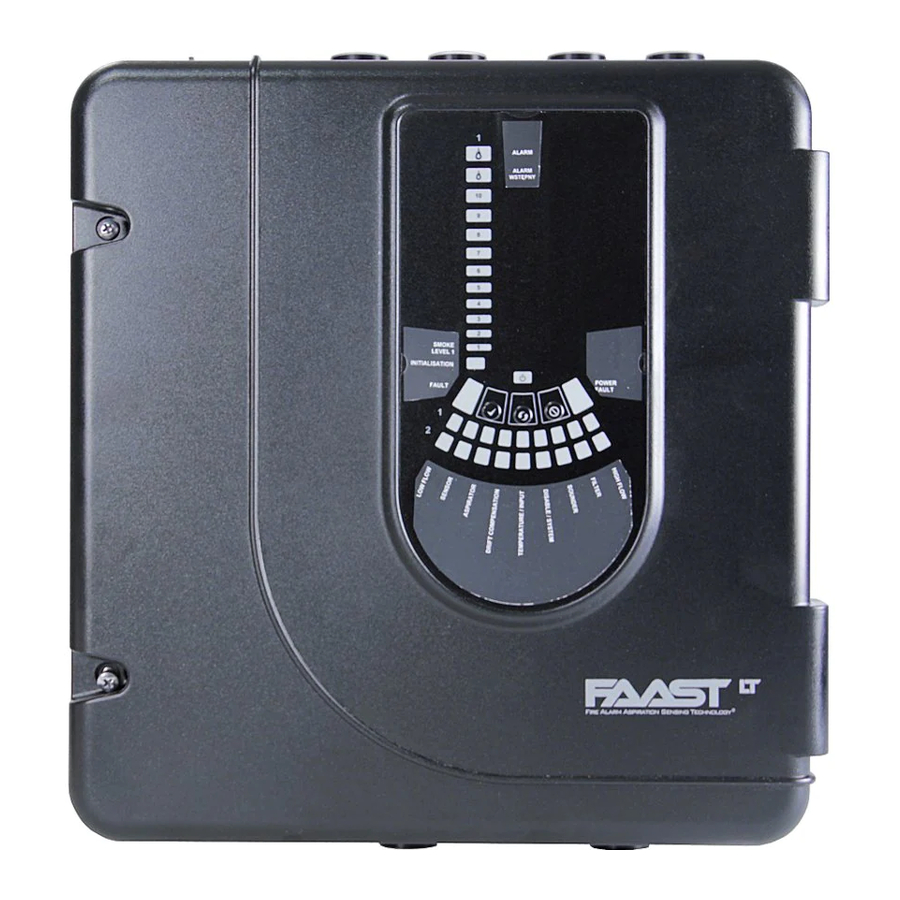
INTRODUCTION
The FAAST LT aspirating smoke detector is an advanced smoke
sensing system for use in early warning and very early warning
applications . The system continuously draws air from the controlled
environment through a series of sampling holes to monitor the
environment for smoke particulate . A range of sensing, operating
and output facilities can be configured in the FAAST LT unit by the
end user . This is accomplished by programming and downloading
control parameters from a PC running the proprietary software
application, PipeIQ™ (Version 2.3 and above). This manual
describes how to monitor and configure the various operating
parameters available in a FAAST LT unit via the user interface
provided by PipeIQ™ .
(Power-ON)
INITIALIZATION
Cover
Close
SERVICE
MODE
D200-100-00
ADVANCED SET-UP AND CONTROL GUIDE
Maintenance Timeout or after TEST + RESET + DISABLE (When Device Configuration has been Changed)
RESET + Password Enter (During Auto Speed Procedure)
Maintenance Timeout or after
TEST + RESET + DISABLE
(No Need for Device to Initialize)
NORMAL
RESET +
Password Enter
RESET +
DISABLE
Cover
Open
DISPLAY
FAN
SPEED
FAAST LT
FIRE ALARM ASPIRATION SENSING TECHNOLOGY
Further PipeIQ™ Capabilities . . . . . . . . . . . . . . . . . . . . . . . . . . 5
2
PipeIQ™ Help
Appendices
2
3
A: FAAST LT Config. Parameters and Default Set-Up Values . 6
3
3
Default Set-Up Values - Stand Alone Versions
3
Default Set-Up Values - Loop Based Versions
4
B: FAAST LT Fault Codes . . . . . . . . . . . . . . . . . . . . . . . . . . . . .14
4
C: Example Pipe Configurations . . . . . . . . . . . . . . . . . . . . . . . .16
4
4
4
Keep this document for future reference
THE FAAST LT FUNCTIONAL STATE DIAGRAM.
In operation, the device can be in one of 6 possible states:
Initialization
Normal
Maintenance
Remote Maintenance
Service Mode
Power Out Of Range state
The routes in and out of these states are shown in the diagram
below .
MAINTENANCE
Cover Open +
USB
Disconnected
Connected
+ Cover Close
REMOTE
MAINTENANCE
1
Power in Correct Range
Power < 18V
Power > 32V
USB
POWER OUT OF
RANGE STATE
®
5
5
5
5
6
10
12
I56-3888-005
Advertisement
Table of Contents

Related Manuals for System Sensor FAAST LT


Summary of Contents for System Sensor FAAST LT
- Page 1 The FAAST LT Functional State Diagram . . . . . . . . . . . . . . . . . 1...
- Page 2 . The front panel buttons are enabled for maintenance parameters to suit local fire codes and standards and generate functions and the FAAST LT unit can be linked to a PC . (See pipe layout diagrams, BoMs, parameter tables and event log Remote Maintenance state) .
- Page 3 To connect and communicate with a FAAST LT device via the FAAST LT unit . Therefore this option should not be used to set PC USB port, PipeIQ™ must be running a project (.mdf file) that or change air flow values in an EN54 compliant pipe system;...
- Page 4 USB link; see In the common chamber version of the FAAST LT ( 1 channel - 2 Sending a Configuration to a FAAST LT Device section.
- Page 5 FURTHER PIPEIQ™ CAPABILITIES Using Help - Display Pane (Right Pane) The Display pane on the right of the online help displays the Creating a Project content for the selected topic . To create a project select New from the File menu or click on the Blue Underlined Text Indicates a link to a different topic .
- Page 6 FAAST LT CONFIGURATION PARAMETERS AND DEFAULT SET-UP VALUES A1: FAAST LT CONFIGURATION PARAMETERS All the FAAST LT configurable parameters are described in Table A1 below . The default values set into the unit at manufacture are listed in Tables A2 and A3. The user can change parameter values using the PipeIQ™...
- Page 7 PARAMETER PARAMETER DESCRIPTION COMMENTS RANGE Channel 1 alarm is YES/NO NO: When alarm condition is reached, the latched device activates the alarm relay . When the Channel 2 alarm is YES/NO alarm condition is removed the alarm relay is ...
- Page 8 PARAMETER PARAMETER DESCRIPTION COMMENTS RANGE Auxiliary relay set on YES/NO User chooses the event(s) that will It is possible to have more than one low/high temperature activate the auxiliary relay . event set the Aux relay . If any one alert NO: not used of the chosen events occurs, the...
- Page 9 PARAMETER PARAMETER DESCRIPTION COMMENTS RANGE Monday is holiday YES/NO Allows use of different alarm and pre- alarm levels on one or more days of the Tuesday is holiday YES/NO week Wednesday is holiday YES/NO NO: Device will change between day and night settings at selected times (if Thursday is holiday YES/NO...
- Page 10 A2: FAAST LT DEFAULT SET-UP VALUES All the default value settings are listed in the following two tables . Table A2 refers to Stand Alone units, whilst Table A3 refers to Loop Based (addressable) units . X means that a parameter is not applicable .
- Page 11 1 Channel 1 Channel 2 Channel PARAMETER PARAMETER RANGE 1 Sensor 2 Sensor 2 Sensor Auxiliary relay set on flow fault YES/NO Auxiliary relay set on sensor YES/NO communication fault Auxiliary relay set on power restart YES/NO alert Auxiliary relay is latched YES/NO External input normal state OPEN, SHORT...
- Page 12 Table A3: Loop Based (Addressable) Versions 1 Channel 1 Channel 2 Channel PARAMETER PARAMETER RANGE 1 Sensor 2 Sensor 2 Sensor Maintenance Password 1111 - 9999 3111 3111 3111 Current configuration number 0..255 Current configuration date DD/MM/YY HH:MM:SS Channel 1 enabled YES/NO Channel 2 enabled YES/NO...
- Page 13 1 Channel 1 Channel 2 Channel PARAMETER PARAMETER RANGE 1 Sensor 2 Sensor 2 Sensor External input normal state OPEN, SHORT OPEN OPEN OPEN External input triggers fault YES/NO External input silences sounders YES/NO External input reset device YES/NO External input disables ASD YES/NO External input ASD disabling time 1..1440 min...
- Page 14 Error in communication In SA variant, it is given when sensor doesn’t answer COMMUNICATION with sensor 1 . to FAAST LT unit or sensor reports low chamber FAULT S1 signal . In LB, sensor alarm mode, it is given when sensor remote output is OFF for configured timeout .
- Page 15 . ALERT Alert [A006] LOW POWER Device supply voltage is Check the voltage . Changing the FAAST LT unit ALERT under 21 V (nominal) . parameter, it is possible to monitor either the main or both power supplies...
- Page 16 APPENDIX C EXAMPLE PIPE CONFIGURATIONS - 1 CHANNEL (can be duplicated for 2 channel units) D200-100-00 I56-3888-005...
- Page 17 Hole 9 Hole 8 Hole 7 Hole 6 Hole 5 Hole 4 Hole 3 Hole 2 Hole 1 Hole 10 Hole 11 Hole 12 Hole 13 Hole 14 Hole 15 Hole 16 Hole 17 Hole 18 D200-100-00 I56-3888-005...
- Page 18 EXAMPLE PIPE CONFIGURATIONS USING EXTERNAL FILTER Example Pipe Configuration 1 Channel Single Pipe With Filter - Class C End hole (Hole 8) Hole 5 Hole 1 Hole 2 Hole 3 Hole 4 Hole 6 Hole 7 FILTER HOLE SPEED SIZE (mm) Example Pipe Configuration 1 Channel Single Pipe With Filter - Class B...
- Page 19 System Sensor Europe Pittway Tecnologica S.r.l. Via Caboto 19/3 34147 TRIESTE Italy http://www.systemsensoreurope.com D200-100-00 I56-3888-005...
Need help?
Do you have a question about the FAAST LT and is the answer not in the manual?
Questions and answers