Table of Contents
Advertisement
Quick Links
INSTALLATION AND MAINTENANCE INSTRUCTIONS
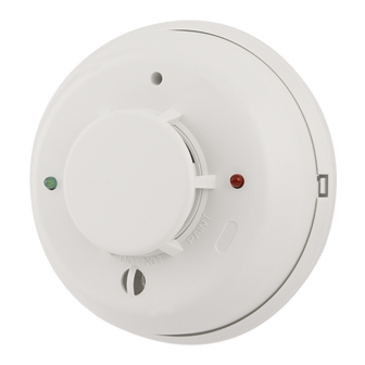
2112/24S and 2112/24TS
Photoelectronic Smoke Detectors
Specifications
Diameter:
Height (including mounting bracket):
Weight:
Operating Temperature Range
Model 2112/24S:
Model 2112/24TS:
Operating Humidity Range:
Latching Alarm:
Heat Sensor (2112/24TS only):
Electrical Ratings
System Voltage (nominal):
Minimum:
Maximum:
Maximum Ripple Voltage:
Standby Current:
Alarm Current:
Reset Voltage:
Reset Time:
Start-up Time:
EOL Relay:
Alarm Initiation Contact Ratings
Resistive or Inductive Load (60% power factor)
Form A:
Before Installing
Please thoroughly read the System Sensor manual I56-407,
Guide for Proper Use of System Smoke Detectors, which pro-
vides detailed information on detector spacing, placement,
zoning, wiring, and special applications. Copies of this
manual are available at no charge from System Sensor.
NOTICE: This manual shall be left with the owner/user of
this equipment.
IMPORTANT: This detector must be tested and maintained
following NFPA 72 requirements. The detector should be
cleaned at least once a year.
General Description
Model 2112/24S is a 4-wire photoelectronic smoke detector
that uses a state-of-the-art optical sensing chamber. This
detector is designed to provide open area protection. Model
2112/24TS features a restorable, built-in, fixed-temperature
(135°F) thermal detector.
D200-62-00
Technical Manuals Online! - http://www.tech-man.com
5.5 inches (140 mm)
1.9 inches (48 mm)
5.3 oz. (150 g)
32° to 120°F (0° to 50°C)
32° to 100°F (0° to 38°C)
10% to 93% Relative Humidity, Noncondensing
Reset by momentary power interruption
135°F Fixed Temperature Electronic Thermistor
12 or 24 VDC
8.5 VDC
35 VDC
30% of nom. Voltage (peak to peak)
50 µ A maximum
17 mA typical, 23 mA max. at 12V
19 mA typical, 25 mA max. at 24V
0.8 VDC minimum
0.3 seconds maximum
30 seconds maximum (after 60 sec. reset)
A77-716B, 12/24 Volt
0.5A @ 30 VAC/DC
Installation of these detectors is simplified by the use of a
mounting bracket and a plug-in screw terminal block that
can be prewired to the system, allowing the detector to be
easily installed or removed for cleaning. The detector's sen-
sitivity can be tested in place using the MOD400R Test
Module.
An LED on the detector provides a local visual indication of
the detector's status. If power is applied to the detector, and
it is functioning normally in standby mode within the listed
sensitivity ranges, the status LED blinks once every ten sec-
onds. The LED also provides a visual indication that main-
tenance is required. If the LED stops blinking, the detector
is either not powered, out of the listed sensitivity range,
and/or unable to function properly. The test switch will not
operate if the detector is below the insensitive limit. The
LED will also latch on when the detector is in alarm.
1
A Division of Pittway
3825 Ohio Avenue, St. Charles, Illinois 60174
1-800-SENSOR2, FAX: 630-377-6495
I56-932-11
Advertisement
Table of Contents

Subscribe to Our Youtube Channel
Related Manuals for System Sensor 2112/24S


Summary of Contents for System Sensor 2112/24S
- Page 1 The detector’s sen- zoning, wiring, and special applications. Copies of this sitivity can be tested in place using the MOD400R Test manual are available at no charge from System Sensor. Module. NOTICE: This manual shall be left with the owner/user of An LED on the detector provides a local visual indication of this equipment.
- Page 2 Mounting insulation from the end of the feed wire, inserting the wire Each 2112/24S and 2112/24TS detector is supplied with a into the appropriate terminal, and tightening the screw to mounting bracket that permits the detector to be mounted: secure the wire in place.
- Page 3 Figure 3. Wiring diagram for the 2112/24S and 2112/24TS detector: POWER DETECTORS – EOL POWER SUPERVISION RELAY (SHOWN ENERGIZED) A77-716 12/24V UL LISTED EOL RESISTOR CONTROL SPECIFIED BY PANEL PANEL MANUFACTURER INITIATING LOOP – OPTIONAL CLASS A WIRING A78-2336-03 : Observe polarity in power and initiating loops when wiring.
- Page 4 Three-Year Limited Warranty System Sensor warrants its enclosed smoke detector to be free from de- ment, RA #__________, 3825 Ohio Avenue, St. Charles, IL 60174. Please fects in materials and workmanship under normal use and service for a include a note describing the malfunction and suspected cause of failure.
Need help?
Do you have a question about the 2112/24S and is the answer not in the manual?
Questions and answers