Table of Contents
Advertisement
Advertisement
Table of Contents

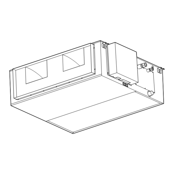
Summary of Contents for Fujitsu ART36AL(3)H
-
Page 1: Duct Type
PERATING ANUAL AIR CONDITIONER DUCT TYPE Indoor Unit ART36AL(3)H ART36RL(3)H ART45AL(3)H ART45RL(3)H ART60AL(3) ART60RL(3) Outdoor Unit AOT36AC(3) AOT36RC(3) AOT45AC(3) AOT45RC(3) AOT60AB(3) AOT60RB(3) KEEP THIS OPERATION MANUAL FOR FUTURE REFERENCE FUJITSU GENERAL LIMITED P/N9362589017... -
Page 2: Table Of Contents
CONTENTS SAFETY PRECAUTIONS .......... 3 CARE AND MAINTENANCE ........10 NAME OF PARTS ............4 ERRORS AND SELF DIAGNOSIS ......10 PREPARATION ............6 OPERATING TIPS ............ 11 OPERATION .............. 6 SYSTEM OPERATION ..........12 TIMER OPERATION ..........8 TROUBLESHOOTING ..........13 ENERGY SAVE OPERATION ........ -
Page 3: Safety Precautions
SAFETY PRECAUTIONS G Before using the appliance, read these “PRECAUTIONS” thoroughly and operate in the correct way. G The instructions in this section all relate to safety; be sure to maintain save operating conditions. G “CAUTION” and “DANGER” have the following meanings in these instructions: This mark indicates procedures which, if improperly performed, might lead to the DANGER! death or serious injury of the user. -
Page 4: Name Of Parts
NAME OF PARTS Instructions relating to heating(*) are applicable only to “HEAT & COOL MODEL” (Reverse Cycle). Fig. 3 Fig. 1 Fig. 2 Electrical Breaker This breaker is installed during the electrical installation. Fig. 4 CLOCK TEMP. NON STOP FAN AUTO °... - Page 5 Fig. 1 Indoor Unit Fig. 4 Remote Controller 1 Outlet Port 6 START/STOP Button 2 Intake Port 7 Operation Lamp 3 Drain Hose 8 ZONE CONTROL Button 9 ZONE CONTROL Lamp : ENERGY SAVE Button A ENERGY SAVE Lamp B CLOCK ADJUST Button C TIMER MODE Button D SET TIME Button (L / M) E SET TEMP.
-
Page 6: Preparation
PREPARATION Set the Current Time NON STOP CLOCK TEMP. FAN AUTO Press the CLOCK ADJUST button for more than ° HEAT OFF ON FAN HIGH TIMER FAN MED TIMER three seconds. COOL PROGRAM FAN LOW DEFROST TEST REPEAT The current time display will flash. TIMER MASTER MODE... - Page 7 To Set the Thermostat Press the SET TEMP. button. CLOCK TEMP. NON STOP FAN AUTO ° HEAT OFF ON FAN HIGH L : Press to raise the thermostat setting. TIMER FAN MED TIMER COOL PROGRAM FAN LOW M : Press to lower the thermostat setting. DEFROST TEST REPEAT...
-
Page 8: Timer Operation
TIMER OPERATION Press the START/STOP button; after the unit starts operation perform the following procedure: OFF Timer / ON Timer Press the TIMER MODE button and display either OFF CLOCK TEMP. NON STOP FAN AUTO ° HEAT OFF ON FAN HIGH TIMER FAN MED Timer or ON Timer. -
Page 9: Energy Save Operation
To Cancel the Timer Mode To confirm or Change Settings To Change the Timer Setting During Timer Operation Before Starting Operation During Operation G To confirm settings G OFF Timer / ON Timer Press the TIMER MODE button and set the display to “NON STOP”... -
Page 10: Care And Maintenance
CARE AND MAINTENANCE G Before cleaning the unit, be sure to stop the unit and disconnect the power supply. CAUTION! G Turn off the electrical breaker. G A fan operates at high speed inside the unit, and personal injury could result. Installing the Air Filter Be sure the filter is always installed in the inlet air grille of the indoor unit. -
Page 11: Operating Tips
OPERATING TIPS Instructions relating to heating(*) are applicable only to “HEAT & COOL MODEL” (Reverse Cycle). Operation and Performance *Heating Performance *Microcomputer-controlled Automatic Defrosting G This air conditioner uses a heat pump which absorbs G When the outside temperature is low and the humid- heat from outside air and brings it indoors. -
Page 12: System Operation
SYSTEM OPERATION There are different ways the unit can be controlled. (Consult the remote controller operating instructions for details on setting the operating functions). <Spare Remote Controller> <Control Several Units with just one Remote Controller> Two remote controllers can be connected to one air condi- One remote controller can control up to 16 air conditioners. -
Page 13: Troubleshooting
TROUBLESHOOTING Instructions relating to heating(*) are applicable only to “HEAT & COOL MODEL” (Reverse Cycle). In the event of a malfunction (burning smell, etc.), immediately stop operation, turn off the elec- DANGER! trical breaker, and consult authorized service personnel. Always be sure to turn off the electrical breaker to ensure that power is completely off. Before requesting service, perform the following checks: Symptom See Page...


Need help?
Do you have a question about the ART36AL(3)H and is the answer not in the manual?
Questions and answers