Sign In
Upload
Manuals
Brands
Thermal Dynamics Manuals
Welding System
PAK Master 150XL
Thermal Dynamics PAK Master 150XL Cutter Manuals
Manuals and User Guides for Thermal Dynamics PAK Master 150XL Cutter. We have
3
Thermal Dynamics PAK Master 150XL Cutter manuals available for free PDF download: Service Manual, Operating Manual
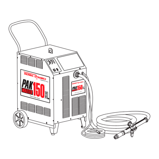
Thermal Dynamics PAK Master 150XL Service Manual (98 pages)
Automated Plasma Cutting Power Supply
Brand:
Thermal Dynamics
| Category:
Welding System
| Size: 4.99 MB
Table of Contents
Table of Contents
4
General Information
7
Notes, Cautions and Warnings
7
Important Safety Precautions
7
Publications
8
Note, Attention Et Avertissement
9
Precautions de Securite Importantes
9
Documents de Reference
11
Declaration of Conformity
13
Statement of Warranty
14
Introduction
15
Scope of Manual
15
General Service Philosophy
15
Service Responsibilities
15
Description
17
Scope of Manual
17
Power Supply General Description
17
Specifications/Design Features
18
Power Supply Options and Accessories
19
Theory of Operation
20
Service
21
Introduction
21
Periodic Inspection & Procedures
21
System Theory
23
Common Operating Problems
25
Troubleshooting Guide - General Information
26
Circuit Fault Isolation
27
Main Input and Internal Power Problems
28
Pilot Arc Problems
30
Main Cutting Arc Problems
32
Test Procedures
33
Replacement Procedures
41
Introduction
41
Anti-Static Handling Procedures
41
Parts Replacement - General Information
41
Major External Parts Replacement
42
Access Panel Parts Replacement
43
Left Side Center Chassis Parts Replacement
44
Right Side Center Chassis Parts Replacement
48
Base Parts Replacement
54
Rear Panel Parts Replacement
56
Parts Lists
59
Introduction
59
Ordering Information
59
Major External Replacement Parts
60
Access Panel Replacement Parts
61
Left Side Center Chassis Replacement Parts
62
Right Side Center Chassis Replacement Parts
64
Base Replacement Parts
66
Rear Panel Replacement Parts
68
Options and Accessories
70
Appendix 1: Input Wiring Requirements
71
Appendix 2: Sequence of Operation (Block Diagram
72
Appendix 3: Pot/Led Pc Board Layout
73
Appendix 4: Logic Pc Board Layout
74
Appendix 5: Gate Drive Pc Board Layout
76
Appendix 6: Pilot/Output Pc Board Layout and Wiring Connection Diagram
78
Appendix 7: CD Pc Board Layout
80
Appendix 8: Input Pc Board Layout
81
Appendix 9: Fet Pc Board Layout
82
Appendix 10: Capacitor Pc Board Layout
84
Appendix 11: Current Sensor Pc Board Layout
85
Appendix 12: 36Vac Circuit Diagram
86
Appendix 13: Recommended Routine Maintenance Schedule for Liquid Cooled Plasma Cutting Systems
87
Appendix 14: Typical Mechanized System Grounding Diagram
88
Appendix 15: Power Supply Cnc Interface Diagram Without Standoff Control
89
Appendix 16: Typical Mechanized System Cable Interconnection Diagram
90
Appendix 17: Quick Reference to Interconnecting Cables and Hoses
91
Advertisement
Thermal Dynamics PAK Master 150XL Service Manual (90 pages)
PLASMA CUTTING POWER SUPPLY
Brand:
Thermal Dynamics
| Category:
Welding System
| Size: 3.64 MB
Table of Contents
Table of Contents
4
General Information
7
Notes, Cautions and Warnings
7
Important Safety Precautions
7
Publications
8
Note, Attention Et Avertissement
9
Precautions de Securite Importantes
9
Documents de Reference
11
Declaration of Conformity
13
Statement of Warranty
14
Introduction
15
Scope of Manual
15
General Service Philosophy
15
Service Responsibilities
15
Section 2 Introduction
15
Description
17
Scope of Manual
17
Power Supply General Description
17
Section 3 Description
17
Specifications/Design Features
18
Power Supply Options and Accessories
19
Theory of Operation
19
Service Troubleshooting
21
Introduction
21
Periodic Inspection & Procedures
21
Section 4 Service Troubleshooting
21
System Theory
23
Common Operating Problems
24
Troubleshooting Guide - General Information
25
Circuit Fault Isolation
26
Main Input and Internal Power Problems
27
Pilot Arc Problems
29
Main Cutting Arc Problems
31
Test Procedures
32
Replacement Procedures
39
Introduction
39
Anti-Static Handling Procedures
39
Parts Replacement - General Information
39
Section 5 Replacement Procedures
39
Major External Parts Replacement
40
Access Panel Parts Replacement
41
Left Side Center Chassis Parts Replacement
42
Right Side Center Chassis Parts Replacement
45
Base Parts Replacement
51
Rear Panel Parts Replacement
54
Parts Lists
57
Introduction
57
Ordering Information
57
Major External Replacement Parts
58
Access Panel Replacement Parts
59
Left Side Center Chassis Replacement Parts
60
Right Side Center Chassis Replacement Parts
62
Base Replacement Parts
64
Rear Panel Replacement Parts
66
Options and Accessories
68
Appendix 1: Input Wiring Requirements
69
Appendix 2: Sequence of Operation (Block Diagram
70
Appendix 3: Pot/Led Pc Board Layout
71
Appendix 4: Logic Pc Board Layout
72
Appendix 5: Gate Drive Pc Board Layout
74
Appendix 6: Pilot/Output Pc Board Layout
78
Appendix 7: CD Pc Board Layout
78
Appendix 8: Input Pc Board Layout
79
Appendix 9: Fet Pc Board Layout
80
Appendix 10: Capacitor Pc Board Layout
82
Appendix 11: Current Sensor Pc Board Layout
83
Appendix 12: 36Vac Circuit Diagram
84
Appendix 13: Recommended Routine Maintenance Schedule
85
For Liquid Cooled Plasma Cutting Systems
85
APPENDIX 14: SYSTEM SCHEMATIC (Unit Rev AQ or Earlier
86
APPENDIX 14: SYSTEM SCHEMATIC (Unit Rev AR or Later
88
Thermal Dynamics PAK Master 150XL Operating Manual (60 pages)
PLASMA CUTTING POWER SUPPLY
Brand:
Thermal Dynamics
| Category:
Welding System
| Size: 3.26 MB
Table of Contents
Table of Contents
4
General Information
7
Notes, Cautions and Warnings
7
Important Safety Precautions
7
Publications
8
Note, Attention Et Avertissement
9
Precautions de Securite Importantes
9
Documents de Reference
11
Declaration of Conformity
13
Statement of Warranty
14
Introduction
15
Scope of Manual
15
Power Supply General Description
15
Section 2 Introduction
15
Specifications/Design Features
16
Power Supply Options and Accessories
17
Theory of Operation
18
Installation
19
Introduction
19
Site Selection
19
Unpacking
19
Transporting Options
19
Section 3 Installation
19
Input Power Connections
20
Input Voltage Selection
20
Input Power Cable Connections
22
Gas Connections
23
Connecting Torch Leads
27
Ground Connections for Mechanized Applications
30
Filling Power Supply Coolant
32
Operation
33
Introduction
33
Operating Controls
33
Section 4 Operation
33
Sequence of Operation
36
Preparations for Operating
36
Cut Quality
37
System Operation
39
Optional Power Supply Settings
39
Service
41
Introduction
41
General Maintenance
41
Common Operating Faults
43
Common Operating Problems
43
Troubleshooting Guide
44
Power Supply Parts Replacement
47
Parts Lists
49
Introduction
49
Ordering Information
49
System Replacement
50
Power Supply Replacement
50
Basic Replacement Parts
51
Options and Accessories
51
Appendix 1: Input Wiring Requirements
53
Appendix 2: Sequence of Operation Block Diagram
54
Appendix 3: Grounding Diagram
55
Appendix 4: Routine Maintenance Schedule
56
Appendix 5: Power Supply Cnc Interface Diagram
57
Appendix 6: Schematic Diagram
58
Advertisement
Advertisement
Related Products
Thermal Dynamics CUTMASTER 102
Thermal Dynamics CUTMASTER 151
Thermal Dynamics 101 CUTMASTER
Thermal Dynamics 152 CUTMASTER
Thermal Dynamics SIGNATURE PAK 1250XRTM
Thermal Dynamics 1-4730-6
Thermal Dynamics 1-4200-6
Thermal Dynamics CutMaster 151 (CE)
Thermal Dynamics Pak Master 25
Thermal Dynamics CE Pak Master 100XL Plus
Thermal Dynamics Categories
Welding System
Power Supply
Cutter
Controller
Flashlight
More Thermal Dynamics Manuals
Login
Sign In
OR
Sign in with Facebook
Sign in with Google
Upload manual
Upload from disk
Upload from URL