GW Instek PSH series User Manual
Programmable power supply
Hide thumbs
Also See for PSH series:
- Programmer's manual (25 pages) ,
- User manual (78 pages) ,
- User manual (39 pages)
Table of Contents
Advertisement
Quick Links
Programmable Power Supply
PSH series
USER MANUAL
GW INSTEK PART NO. XXXX-XXXXXX
ISO-9001 CERTIFIED MANUFACTURER
This manual contains proprietary information, which is protected
by copyrights. All rights are reserved. No part of this manual may
be photocopied, reproduced or translated to another language
without prior written consent of Good Will company.
The information in this manual was correct at the time of printing.
However, Good Will continues to improve products and reserves
the rights to change specification, equipment, and maintenance
procedures at any time without notice.
Good Will Instrument Co., Ltd.
No. 7-1, Jhongsing Rd., Tucheng City, Taipei County 236, Taiwan.
Advertisement
Chapters
Table of Contents

Subscribe to Our Youtube Channel
Related Manuals for GW Instek PSH series


Summary of Contents for GW Instek PSH series
- Page 1 Programmable Power Supply PSH series USER MANUAL GW INSTEK PART NO. XXXX-XXXXXX This manual contains proprietary information, which is protected by copyrights. All rights are reserved. No part of this manual may be photocopied, reproduced or translated to another language without prior written consent of Good Will company.
-
Page 2: Table Of Contents
Calibration ............61 PSH Overview ..........11 Calibration Preparation ......62 Entering calibration mode ......63 Main Features ..........12 Output Voltage calibration......64 PSH Series Lineup........13 Output Current calibration ......66 Package Contents ........14 OVP Calibration ........68 Front Panel ..........16 Rear Panel ..........18 FAQ ...............69 Display............19... -
Page 3: Safety Instructions
Safety Instructions PSH User Manual Safety Symbols Safety Instructions These safety symbols may appear in this manual or on PSH. This chapter contains important safety instructions that must be followed when Warning: Identifies conditions or practices that operating PSH and when keeping it in storage. could result in injury or loss of life. - Page 4 Safety Instructions PSH User Manual at the source of low-voltage installation. xylene, and acetone. Measurement category III is for measurement performed in the building installation. Location: Indoor, no direct sunlight, dust free, Operation Measurement category II is for measurement performed almost non-conductive pollution (Note below) Environment on the circuits directly connected to the low voltage...
-
Page 5: Power Cord For The United Kingdom
Safety Instructions Power cord for the United Kingdom When using PSH in the United Kingdom, make sure the power cord meets the following safety instructions. NOTE: This lead / appliance must only be wired by competent persons WARNING: THIS APPLIANCE MUST BE EARTHED IMPORTANT: The wires in this lead are coloured in accordance with the following code: Green/ Yellow:... -
Page 6: Psh Overview
Remote control interface equipped with Constant current operation • SCPI command set and Lab-View Driver facilitates ATE software development. Output On/Off control • This chapter describes PSH series features and Built-in buzzer • appearances in a nutshell. Self test and calibration • LCD display Main Features ......... -
Page 7: Psh Series Lineup
PSH User Manual PSH Series Lineup Package Contents PSH series consist of the following 12 models with various output Check the contents before using PSH series. Contact your local voltage and current ratings. For the detailed specifications, see dealer in case there is a missing item. -
Page 8: Front Panel
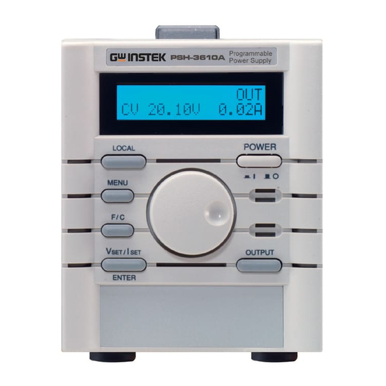
PSH Overview PSH User Manual Package Contents (cont.) Front Panel Terminal cover Output • connection kit Output cable screw • User manual (this document) Manual • Programming manual • Shows the output and the configuration status. LCD Display See page19 for details. Power Switch Sets parameters. -
Page 9: Rear Panel
PSH Overview PSH User Manual Rear Panel Switches between voltage setting mode and Vset/ Iset/ current setting mode, or confirm the entered Enter key value in the menu mode (see page44). Vset (edit Voltage) Iset (edit Current) SET 2.58V 2.01A SET 2.58V 2.01A Switches the editing location and resolution:... -
Page 10: Display
PSH Overview PSH User Manual Display (cont.) Display The following displays appear when pressing the Menu mode Display mode Editing mode Default MENU display Menu key . To move to the next configuration, display press the Menu key repeatedly. When inactive for more than 5 seconds, the display goes back to the default mode. -
Page 11: Setup
This chapter describes load configurations and the terminal cover, screw them together. Terminal Cover setup procedures. Follow these instructions to properly install PSH series. AC Power Cable Assembly ......22 AC power cable assembly AC power cable requirement ..... 23 Remote Sensing and Local Sensing .... -
Page 12: Remote Sensing And Local Sensing
Setup PSH User Manual AC power cable requirement Remote Sensing and Local Sensing Here is the AC power cable specification, in case of using cables Remote sensing compensates the cable loss between PSH and load, other than the attached one. up to 0.5V. -
Page 13: Load / Remote Sensing Wire Selection
Setup PSH User Manual Load / Remote Sensing Wire Selection Load Configuration The following instructions apply to both load wire and remote Select the appropriate configuration for the target application. sensing wire, unless noted. For local sensing and remote sensing explanation, see the previous page. - Page 14 Setup PSH User Manual Single PSH + multiple Load Multiple PSH + single load (series operation) Output current for each load follows the load Up to four PSH series (with identical output Condition Condition • • requirement. ratings) can be cascaded.
-
Page 15: Load Wire Assembly
Setup PSH User Manual Series Operation (cont.) Load Wire Assembly Series Select the appropriate wire according to the 1. Wire —OUT —IN Operation + guideline on page25. selection PSH #1 Load Remote +OUT Sensing Replace the two screws on the output terminal 2. -
Page 16: Remote Sensing Wire Assembly
Setup PSH User Manual Load Wire Assembly (cont.) Remote Sensing Wire Assembly Screw the output terminal cover to the rear 4. Terminal Select the appropriate wire according to the guideline on page25. panel. cover assembly The sense terminal is connected to the output Local sensing monitor terminal with bare wires. -
Page 17: Functionality Check
Setup PSH User Manual Remote Sensing Wire Assembly (cont.) Functionality Check To minimize noise effect, we recommend 5. Wire shield Check the PSH basic functionalities before operation. covering the remote sensing wire with ground connection shield and connect it to the ground terminal. Preparation Output Voltage Check items... -
Page 18: Output Voltage & Ovp Check
Output Voltage & OVP Check OUTPUT 5. Press the Output key and turn On the output. Connection The display changes into CV (Constant Voltage) mode and PSH Series shows the OUT sign on the top CV 20.00V 18.00A — Digital Multimeter right corner. -
Page 19: Output Current Check
Setup PSH User Manual Output Current Check OCP Check Connection Connection Current Digital Multimeter PSH Series Current Digital Multimeter PSH Series Shunt — Shunt — Checking step Checking step 1. Power On PSH and connect the Multimeter/ Current Shunt 1. Power On PSH and connect the Multimeter / Current Shunt terminal. -
Page 20: Rack Mounting (Optional)
Setup PSH User Manual The OCP sign appears on the upper side of the display. Rack Mounting (Optional) CV 20.00V 18.00A PSH can be mounted on standard 19 inch rack using GRA-403 OUTPUT rack mounting kit. 4. Press the Output key and turn On the output. -
Page 21: (Optional) Rack Mounting Assembly
Setup PSH User Manual Rack mounting assembly 4. Main bracket 1. Rack Fix the PSH to the main bracket using M3 Confirm the rack mount layout. Make sure there assembly mounting layout screws. is a space between each PSH. Below is the example of rack mounting layout. -
Page 22: Panel Operation
Panel Operation PSH User Manual Menu Key Overview Panel Operation MENU Press the Menu key . To move to the next item, press the This chapter describes the manual operations Menu key repeatedly. done at the front panel, together with the constant voltage/ constant current crossover Default display characteristics. -
Page 23: Constant Voltage/ Constant Current Crossover Characteristic
Panel Operation PSH User Manual Constant Voltage/ Constant Current Output Voltage Setting Crossover Characteristic Operation PSH series automatically switch 1. Press the Vset/ Iset key between constant voltage mode repeatedly to move the underline SET 2.58V 2.01A and constant current mode, to the Voltage side. -
Page 24: Output Current Setting
Panel Operation PSH User Manual Output Current Setting OVP (Output Voltage Protection) Setting Operation Set the OVP value MENU 1. Press the Vset/ Iset key 1. Press the Menu key OCP OUT repeatedly to move the underline repeatedly until the OVP menu SET 2.58V 2.01A 2.58V... -
Page 25: Ocp (Output Current Protection) Setting
Panel Operation PSH User Manual OCP (Output Current Protection) Setting Display Contrast Setting Turn the OCP On/Off Operation MENU MENU 1. Press the Menu key 1. Press the Menu key OCP OUT OCP OUT repeatedly until the OCP menu repeatedly until the Contrast 2.58V 2.01A 2.58V... -
Page 26: Buzzer Sound Setting
Panel Operation PSH User Manual Buzzer sound Setting Remote Operation This chapter describes the IEEE 488.2 based Operation remote control configuration, command syntax, MENU and command set overview. For further 1. Press the Menu key OCP OUT descriptions and examples, refer to the repeatedly until the Buzzer menu programming manual. -
Page 27: Interface Selection
Remote Operation PSH User Manual 1 2 3 4 5 Pin 2: TxD PC RS-232 pin Pin 3: RxD Interface Selection assignment Pin 5: GND Pin 1, 4, 6 ~ 9: No Connection 6 7 8 9 RS232 (Standard) Null-modem connection, in which transmit (TxD) PSH –... -
Page 28: Gpib (Optional)
Remote Operation PSH User Manual GPIB (Optional) Interface functionality check Refer to the service manual for GPIB module installation. In the remote control mode, the display shows Remote mode Note: The RS232 module has to be replaced with the GPIB “RMT”... -
Page 29: Command Syntax
Remote Operation PSH User Manual Command Set Command Syntax The commands are fully compatible with IEEE488.2 (1992) Commands are non-case sensitive. standard and partially compatible with SCPI (1994) standard. For more detailed information, refer to the Programming Manual which is downloadable from www.gwinstek.com.tw. :chan1:prot:curr <0/1>... -
Page 30: Status Commands
Remote Operation PSH User Manual Status commands Miscellaneous commands *cls Clears all event status registers (Output Queue, *idn? Returns the power supply ID as Manufacturer, Operation Event Status, Questionable Event Model No, Serial No, Firmware version. Status, Standard Event Status) Example: GW.Inc,PSH-2018A,12345678,FW1.00 *ese? Returns the ESER (Event Status Enable... -
Page 31: Calibration
Calibration PSH User Manual Calibration Preparation Calibration At least 30 minutes of warm-up time Calibration • Run calibration when the output exceeds the condition specification, or when the functionality check Temperature: 23 ± 5 °C • (page34) fails. To get the optimal result, make sure PSH is powered for at least 30 minutes Relative Humidity: ≤... -
Page 32: Entering Calibration Mode
Output Voltage calibration 1. Press the Local key for 5 seconds. Connection Please enter the The password entry menu Password: 0 appears. PSH Series — Digital Multimeter 2. Enter the model number as the (PSH-2018A) password. Wheel knob changes the digit. -
Page 33: Output Current Calibration
Multimeter reading: Multimeter reading. 20.03V Wheel knob changes the value. Connection Calibration Current Digital Multimeter PSH Series F/C key moves the cursor Voltmax 20.03V Shunt — before and after the decimal point. 6. Press the Vset/Iset/Enter Calibration to confirm the setting. -
Page 34: Ovp Calibration
Calibration PSH User Manual 5. Adjust the display value to the Multimeter reading: 0.02A Multimeter / Current Shunt OVP Calibration reading. Calibration Wheel knob changes the value. CurrMin 0.02A Connection F/C key moves the cursor No connection required before and after the decimal point. 6. -
Page 35: Faq
The OVP value/ OCP status has not been changed. After editing OVP value and OCP status, press the Vset/Iset/Enter key ENTER to confirm. Otherwise the setting does not change. The front panel does not respond. When in remote control mode, PSH does not respond to panel operations. -
Page 36: Appendix
Appendix PSH User Manual PSH-1036A/ 2018A/ 3610A/ 6006A Appendix Output PSH-1036A 10V, 36A PSH-2018A 20V, 18A PSH-3610A 36V, 10A PSH-6006A 60V, 6A Specifications Regulation Load ≤ 0.1% + 5mV (C.V.) Line ≤ 0.05% + 5mV The specifications apply under the following conditions: PSH is Regulation Load ≤... - Page 37 Appendix PSH User Manual PSH-1070A/ 2035A/ 3620A/ 6012A PSH-10100A/ 2050A/ 3630A/ 6018A Output PSH-1070A 10V, 70A Output PSH-10100A 10V, 100A PSH-2035A 20V, 35A PSH-2050A 20V, 50A PSH-3620A 36V, 20A PSH-3630A 36V, 30A PSH-6012A 60V, 12A PSH-6018A 60V, 18A Regulation Load ≤...
-
Page 38: Declaration Of Conformity
Appendix PSH User Manual Declaration of Conformity Index front panel..........16 GOOD WILL INSTRUMENT CO., LTD. (1) No.7-1, Jhongsing Rd., Tucheng City, Taipei County, Taiwan faq ............69 (2) No. 69, Lu San Road, Suzhou City (Xin Qu), Jiangsu Sheng, China AC input functionality check declare, that the below mentioned product... - Page 39 Index voltage check ........35 configuration ........26 voltage setting ......43, 46 theory..........24 check ...........35 safety guidelines..........6 package contents ........14 symbol..........6 power supply UK power cord........9 safety instruction ........ 7 sound setting ......... 51 protection specification ........... 71 OCP setting ........49 storage environment OVP setting ........48...
Need help?
Do you have a question about the PSH series and is the answer not in the manual?
Questions and answers