GW Instek PSU Series Quick Start Manual
Programmable dc power supply
Hide thumbs
Also See for PSU Series:
- User manual (216 pages) ,
- Programming manual (168 pages) ,
- Quick start manual (34 pages)

Related Manuals for GW Instek PSU Series


Summary of Contents for GW Instek PSU Series
- Page 1 All manuals and user guides at all-guides.com Programmable DC Power Supply PSU Series QUICK START GUIDE GW INSTEK PART NO. 82SU-60250MD1 ISO-9001 CERTIFIED MANUFACTURER...
- Page 2 All manuals and user guides at all-guides.com This manual contains proprietary information, which is protected by copyright. All rights are reserved. No part of this manual may be photocopied, reproduced or translated to another language without prior written consent of Good Will company. The information in this manual was correct at the time of printing.
-
Page 3: Table Of Contents
All manuals and user guides at all-guides.com Table of Contents Table of Contents SAFETY INSTRUCTIONS ........... 2 GETTING STARTED ............6 PSU Series Overview ......6 Appearance .......... 11 OPERATION ..............19 Set Up ..........19 Basic Operation ........22 APPENDIX .............. -
Page 4: Safety Instructions
All manuals and user guides at all-guides.com PSU Series Quick Start Guide AFETY INSTRUCTIONS This chapter contains important safety instructions that you must follow during operation and storage. Read the following before any operation to insure your safety and to keep the instrument in the best possible condition. - Page 5 All manuals and user guides at all-guides.com SAFETY INSTRUCTIONS Do not dispose electronic equipment as unsorted municipal waste. Please use a separate collection facility or contact the supplier from which this instrument was purchased. Safety Guidelines Do not place any heavy object on the PSU. General ...
- Page 6 All manuals and user guides at all-guides.com PSU Series Quick Start Guide Disconnect the power cord before cleaning. Cleaning the PSU Use a soft cloth dampened in a solution of mild detergent and water. Do not spray any liquid.
- Page 7 All manuals and user guides at all-guides.com SAFETY INSTRUCTIONS Power cord for the United Kingdom When using the power supply in the United Kingdom, make sure the power cord meets the following safety instructions. NOTE: This lead/appliance must only be wired by competent persons WARNING: THIS APPLIANCE MUST BE EARTHED IMPORTANT: The wires in this lead are coloured in accordance with the following code:...
-
Page 8: Getting Started
PSU Series Overview Series lineup The PSU series consists of 5 models, covering a number of different current, voltage and power capacities: Model name Voltage Rating Current Rating... - Page 9 All manuals and user guides at all-guides.com GETTING STARTED Main Features High power density: 1500W in 1U Performance Universal input voltage 85~265Vac, continuous operation. Output voltage up to 60V, current up to 200A. Active power factor correction. Features ...
- Page 10 All manuals and user guides at all-guides.com PSU Series Quick Start Guide Accessories Before using the PSU power supply unit, check the package contents to make sure all the standard accessories are included. Standard Part number Description Qty. Accessories Output terminal cover...
- Page 11 All manuals and user guides at all-guides.com GETTING STARTED Optional Part number Description Accessories PSU-01C Cable for 2 units of PSU-Series in parallel mode connection PSU-01B Bus Bar for 2 units of PSU-Series in parallel mode connection PSU-01A Joins a vertical stack of 2 PSU units together.
- Page 12 All manuals and user guides at all-guides.com PSU Series Quick Start Guide GPW-003 Power Cord VCTF 3.5mm /3C, 3m MAX Length, 105 ºC, RNB5-5*3P PSE type Download Name Description psu_cdc.inf PSU USB driver Other Name Description Certificate of traceable calibration...
-
Page 13: Appearance
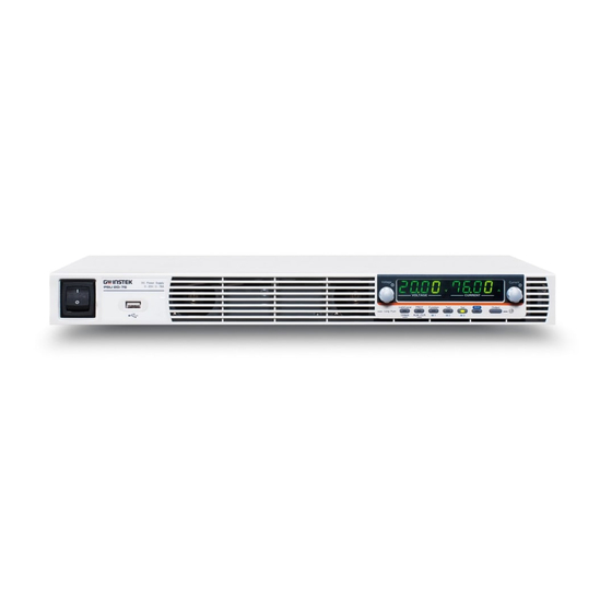
All manuals and user guides at all-guides.com GETTING STARTED Appearance PSU Series Front Panel Display Area Voltage Current DC Power Supply PSU 40-38 0 - 40 V / 0 - 38A VOLTAGE CURRENT Shift Lock/ Local PROT Function Test Output... - Page 14 All manuals and user guides at all-guides.com PSU Series Quick Start Guide Used to lock all front panel 6. Lock/Local Lock/Local buttons other than the Output Button Button or it switches to local Unlock mode. (Long push) Used to unlock the Unlock front panel buttons.
- Page 15 All manuals and user guides at all-guides.com GETTING STARTED Used to enable the functions that 11. Shift Button Shift are written in blue characters below the button. Used to turn output on and off. 12. Output Output Button Lights in green during output ON. 13.
- Page 16 All manuals and user guides at all-guides.com PSU Series Quick Start Guide PSU Series Display and Operation Panel Display Area VOLTAGE CURRENT Displays the voltage or the parameter number of a 14. Voltage Meter Function parameter. Displays the current or the value of a Function 15.
- Page 17 All manuals and user guides at all-guides.com GETTING STARTED The current slew rate enable. 24. ISR LED Lights in green when the memory value are being 25. M1 LED recalled or saved. Lights in green when the memory value are being 26.
- Page 18 All manuals and user guides at all-guides.com PSU Series Quick Start Guide Rear Panel ISOLATED PROGRAMMING 4 - 20mA ISOLATED PROGRAMMING 0 - 5V / 0 - 10V DC OUTPUT RS485 / 232 ANALOG PROGRAMMING 240V S LS 47 63Hz 2000VA MAX.
- Page 19 All manuals and user guides at all-guides.com GETTING STARTED RS 485 / 232 Two different types of cables can 5. Remote-IN be used for RS232 or RS485-based remote control. PSU-232: RS232 cable with DB9 connector kit. PSU-485: RS485 with DB9 connector kit.
- Page 20 All manuals and user guides at all-guides.com PSU Series Quick Start Guide Connector for grounding the output (two 10. Ground positions, shown in red). Screw TED PROGRAMMING 4 - 20mA DC OUTPUT 3 4 5 6 7 8 RS485 / 232...
-
Page 21: Operation
All manuals and user guides at all-guides.com OPERATION PERATION Set Up Line Voltage Connection The PSU power supplies use a universal power Background input that can be used with 100 and 240 Vac systems. To connect or replace the power cord (user supplied, specification below), use the procedure below: The following procedure should only be attempted... - Page 22 All manuals and user guides at all-guides.com PSU Series Quick Start Guide 2. Unscrew the power cord protective sheath. 3. Remove the 2 screws holding the power cord cover and remove. 4. Remove the AC power cord wires with a flat head screwdriver.
- Page 23 All manuals and user guides at all-guides.com OPERATION Power Up 1. Connect the power cord to the Steps Page 19 universal power input. 2. Press the POWER switch on. 3. The power supply will show the Power On settings (Pon) at start up. If no Power On settings are configured, the PSU will recover the state right before the power was last turned OFF.
-
Page 24: Basic Operation
All manuals and user guides at all-guides.com PSU Series Quick Start Guide Basic Operation Setting OVP/OCP/UVL Levels The OVP level and OCP level has a selectable range that is based on the output voltage and output current, respectively. The OVP and OCP level is set to the highest level by default. - Page 25 All manuals and user guides at all-guides.com OPERATION level, and so that the values are not lower than the set UVL trip point. By using this feature, you can avoid turning the output off by mistakenly setting the voltage or current to a value that exceeds the set OVP or OCP level or to a value that is lower than the set UVL trip point.
- Page 26 All manuals and user guides at all-guides.com PSU Series Quick Start Guide 4. Use the current knob to set the Current Setting the protection level for the selected Protection Level function. Setting Range PSU Model OCP 5~220 0.6~6.6 0~6.3 6-200 5~132 1.25~13.75 0~13.12...
- Page 27 All manuals and user guides at all-guides.com OPERATION Set to C.V. Priority Mode When setting the power supply to constant voltage mode, a current limit must also be set to determine the crossover point. When the current exceeds the crossover point, the mode switches to C.C. mode.
- Page 28 All manuals and user guides at all-guides.com PSU Series Quick Start Guide 4. Use the current knob to set the F-03 Current setting. Set F-03 to 0 (CV High Speed Priority) or 2 (CV Slew Rate Priority). 0 = CV High Speed Priority...
- Page 29 All manuals and user guides at all-guides.com OPERATION 9. Use the Voltage knob to set the Voltage voltage. Notice the Set key becomes illuminated when Note setting the current or voltage. If the voltage or current knobs are unresponsive, press the Set key first.
- Page 30 All manuals and user guides at all-guides.com PSU Series Quick Start Guide Set to C.C. Priority Mode When setting the power supply to constant current mode, a voltage limit must also be set to determine the crossover point. When the voltage exceeds the crossover point, the mode switches to C.V.
- Page 31 All manuals and user guides at all-guides.com OPERATION 4. Use the current knob to set the F-03 Current setting. Set F-03 to 1 (CC High Speed Priority) or 3 (CC Slew Rate Priority) and save. 1 = CC High Speed Priority F-03 3 = CC Slew Rate Priority 5.
- Page 32 All manuals and user guides at all-guides.com PSU Series Quick Start Guide 9. Use the Current knob to set the Current current. Notice the Set key becomes illuminated when Note setting the current or voltage. If the voltage or current knobs are unresponsive, press the Set key first.
-
Page 33: Appendix
All manuals and user guides at all-guides.com APPENDIX PPENDIX PSU Dimensions PSU 6-200, PSU 12.5-120, PSU 20-76, PSU 40-38, PSU 60-25 Units = mm Voltage Current DC Power Supply 0 - 40V / 0 - 38A VOLTAGE CURRENT Lock/Local PROT Function Test Shift... -
Page 34: Declaration Of Conformity
All manuals and user guides at all-guides.com PSU Series Quick Start Guide Declaration of Conformity GOOD WILL INSTRUMENT CO., LTD. declare that the below mentioned product Type of Product: Programmable DC Power Supply Model Number: PSU 6-200, PSU 12.5-120, PSU 20-76, PSU 40-38, PSU 60-25...
Need help?
Do you have a question about the PSU Series and is the answer not in the manual?
Questions and answers