GW Instek PSW Series User Manual
Psw series multi-range dc power supply
Hide thumbs
Also See for PSW Series:
- User manual (160 pages) ,
- Service manual (105 pages) ,
- Programming manual (87 pages)
Table of Contents
Advertisement
Quick Links
Download this manual
See also:
Programming Manual
Advertisement
Chapters
Table of Contents

Related Manuals for GW Instek PSW Series


Summary of Contents for GW Instek PSW Series
- Page 1 Multi-Range DC Power Supply PSW Series USER MANUAL GW INSTEK PART NO. 82SW-80400MH1 ISO-9001 CERTIFIED MANUFACTURER...
- Page 2 This manual contains proprietary information, which is protected by copyright. All rights are reserved. No part of this manual may be photocopied, reproduced or translated to another language without prior written consent of Good Will company. The information in this manual was correct at the time of printing. However, Good Will continues to improve products and reserves the rights to change specification, equipment, and maintenance procedures at any time without notice.
-
Page 3: Table Of Contents
SAFETY INSTRUCTIONS Table of Contents SAFETY INSTRUCTIONS ........... 5 GETTING STARTED ............9 PSW Series Overview ......10 Appearance .......... 15 Theory of Operation ......22 OPERATION ..............35 Set Up ..........37 Basic Operation ........57 Parallel / Series Operation ....72 Test Scripts .......... - Page 4 Table of Contents LED Display Format ......161 PSW Specifications ......162 PSW Dimensions ....... 177 Declaration of Conformity ....182 INDEX ................183...
-
Page 5: Safety Instructions
SAFETY INSTRUCTIONS AFETY INSTRUCTIONS This chapter contains important safety instructions that you must follow during operation and storage. Read the following before any operation to insure your safety and to keep the instrument in the best possible condition. Safety Symbols These safety symbols may appear in this manual or on the instrument. -
Page 6: Safety Guidelines
PSW Series User Manual Do not dispose electronic equipment as unsorted municipal waste. Please use a separate collection facility or contact the supplier from which this instrument was purchased. Safety Guidelines Do not place any heavy object on the PSW. - Page 7 SAFETY INSTRUCTIONS Disconnect the power cord before cleaning. Cleaning the PSW Use a soft cloth dampened in a solution of mild detergent and water. Do not spray any liquid. Do not use chemicals containing harsh material such as benzene, toluene, xylene, and acetone. Location: Indoor, no direct sunlight, dust free, Operation ...
- Page 8 PSW Series User Manual Power cord for the United Kingdom When using the power supply in the United Kingdom, make sure the power cord meets the following safety instructions. NOTE: This lead/appliance must only be wired by competent persons WARNING: THIS APPLIANCE MUST BE EARTHED...
-
Page 9: Getting Started
After going through the overview, please read the theory of operation to become familiar with the operating modes, protection modes and other safety considerations. PSW Series Overview ............10 Series lineup ......................10 Main Features ......................11 Accessories ........................ 12 PSW 30/80/160 Accessories .............. -
Page 10: Psw Series Overview
PSW Series User Manual PSW Series Overview Series lineup The PSW series consists of 15 models, divided into 3 different model types covering 3 power capacities: Type I (360 Watt), Type II (720 Watt) and Type III (1080 Watt). Throughout the user manual, PSW 30, PSW 80,... -
Page 11: Main Features
GETTING STARTED Apart from the differences in output, each unit differs in size. The 720 and 1080 watt models are larger than the 360 watt models to accommodate the increase in power. 360 Watt models 720 Watt models 1080 Watt models Type I Type II Type III... -
Page 12: Accessories
PSW Series User Manual Ethernet port Interface Analog connector for analog voltage and current monitoring USB host and device port Accessories Please check the contents before using the PSW. PSW 30/80/160 Accessories Standard Part number Description Accessories... -
Page 13: Psw 250/800 Accessories
GETTING STARTED PSW-002 Simple IDC Tool PSW-003 Contact Removal Tool PSW-005 Series operation cable for 2 units. PSW-006 Parallel operation cable for 2 units. PSW-007 Parallel operation cable for 3 units. GRA-410-J Rack mount adapter (JIS) GRA-410-E Rack mount adapter (EIA) GUG-001 GPIB to USB adapter GTL-240... - Page 14 PSW Series User Manual PSW-008 Basic Accessory Kit: (Air filter x1, Analog control protection dummy x1, Analog control lock level x1 Optional Part number Description Accessories GET-002 Extended terminal PSW-001 Accessory Kit: Pin contact x10, Socket x1, Protection cover x1...
-
Page 15: Appearance
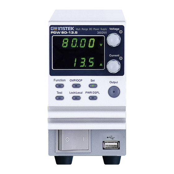
GETTING STARTED Appearance PSW Front Panel 720W: PSW 30-72, 80-27, 160-14.4, 250-9, 800-2.88 Voltage Voltage Multi-Range DC Power Supply PSW 30-72 720W Display knob Current Current knob Cover panel Function OVP/OCP Output Output Test Lock/Local PWR DSPL Power Function switch keys USB A port... - Page 16 PSW Series User Manual The Function keys along with the Output key will Function Keys light up when a key is active. The Function key is used to Function configure the power supply. Set the over current or over OVP/OCP voltage protection levels.
- Page 17 GETTING STARTED Power bar Indicates the current power output as a percentage. Sets the voltage. Voltage Knob Voltage Sets the current. Current Knob Current Press to turn on the output. The Output Output Output key will light up when the output is active.
-
Page 18: Rear Panel
PSW Series User Manual Rear Panel 720W: PSW 30-72, 80-27, 160-14.4 Sense+ USB B Output Analog control terminal port terminal connector Chassis ground Sense- SER.NO. LABEL terminal Output terminal (-) 240V 47 63Hz 1000VA MAX. AC Input 1080W: PSW 30-108, 80-40.5, 160-21.6 360W: PSW 30-36, 80-13.5, 160-7.2... - Page 19 GETTING STARTED 720W: PSW 250-9, 800-2.88 Sense+ USB B Output Analog control terminal port terminals +V connector Sense- terminal SN.C. S SER.NO. LABEL Chassis ground Output terminals -V 240V 47 63Hz 1000VA MAX. AC Input 1080W: PSW 250-13.5, 800-4.32 360W: PSW 250-4.5, 800-1.44 AC Input SN.C.
- Page 20 PSW Series User Manual Standard 26 pin MIL connector Analog Control (OMRON XG4 IDC plug). Connector The analog control connector is used to monitor current and voltage output, machine status (OVP, OCP, OTP etc.), and for analog control of the current and voltage output.
- Page 21 GETTING STARTED The USB B port is used for remote USB B port control. Temperature controlled fans Fans The ethernet port is used for remote Ethernet Port control and digital monitoring from a PC. Type I: PSW 30-36/80-13.5/ Line Voltage Input 160-7.2/250-4.5, 800-1.44 (Type I/TypeII)
-
Page 22: Theory Of Operation
PSW Series User Manual Theory of Operation The theory of operation chapter describes the basic principles of operation, protection modes and important considerations that must be taken into account before use. Operating Area Description The PSW power supplies are regulated DC... - Page 23 GETTING STARTED effective output is actually limited to the power limit of the unit. In this case the output current and voltage then depend purely on the load value. Below is a comparison of the operating areas of each power supply. PSW 800V Series Operating Area 0.45 0.9 1.35 1.44...
- Page 24 PSW Series User Manual PSW 160V Series Operating Area 2.25 4.5 6.75 14.4 21.6 Type I Type II Type III 0 5 10 15 20 25 30 Po… 0 20 40 60 80 Current (A) Cur… PSW 80V Series Operating Area 40.5...
- Page 25 GETTING STARTED PSW 30V Series Operating Area Type I Type II Type III 0 5 10 15 20 25 30 Po… 0 20 40 60 80 Current (A) Cur… CC and CV Mode When the power supply is operating in CC and CV mode constant current mode (CC) a constant current Description...
- Page 26 PSW Series User Manual ), the load resistance (R ) and the critical resistance (R ). The critical resistance is determined by V . The power supply will operate in CV mode when the load resistance is greater than the critical resistance.
-
Page 27: Bleeder Control
GETTING STARTED Slew Rate The PSW has selectable slew rates for CC and Theory CV mode. This gives the PSW power supply the ability to limit the current/voltage draw of the power supply. Slew rate settings are divided into High Speed Priority and Slew Rate Priority. -
Page 28: Internal Resistance
PSW Series User Manual when power is turned off and the load is disconnected. Without a bleed resistor, power may remain charged on the filter capacitors for some time and be potentially hazardous. In addition, bleed resistors also allow for... - Page 29 GETTING STARTED PSW 250-4.5 0.00 ~ 55.55Ω PSW 250-9 0.00 ~ 27.77Ω PSW 250-13.5 0.00 ~ 18.51Ω PSW 800-1.44 0.0 ~ 555.5Ω PSW 800-2.88 0.0 ~ 277.8Ω PSW 800-4.32 0.0 ~ 185.1Ω Alarms The PSW power supplies have a number of protection features. When one of the protection alarms are set, the ALM icon on the display will be lit.
- Page 30 PSW Series User Manual Considerations The following situations should be taken into consideration when using the power supply. When the power supply switch is first turned Inrush current on, an inrush current is generated. Ensure there is enough power available for the power...
- Page 31 GETTING STARTED Current limit level Measured Ammeter current When the power supply is connected to a Reverse Current: regenerative load such as a transformer or Regenerative load inverter, reverse current will feed back to the power supply. The PSW power supply cannot absorb reverse current.
- Page 32 PSW Series User Manual When the power supply is connected to a load Reverse Current: Accumulative such as a battery, reverse current may flow energy. back to the power supply. To prevent damage to the power supply, use a reverse-current- protection diode in series between the power supply and load.
- Page 33 GETTING STARTED Grounding The output terminals of the PSW power supplies are isolated with respect to the protective grounding terminal. The insulation capacity of the load, the load cables and other connected devices must be taken into consideration when connected to the protective ground or when floating.
- Page 34 PSW Series User Manual If the positive or negative terminal is connected Grounded output terminal to the protective ground terminal, the insulation capacity needed for the load and load cables is greatly reduced. The insulation capacity only needs to be greater than the maximum output voltage of the power supply with respect to ground.
-
Page 35: Operation
OPERATION PERATION Set Up ................37 Line Voltage Connection – Type III Models ............37 Filter Installation ...................... 39 Power Up ........................40 Wire Gauge Considerations ..................41 Output Terminals PSW-30/80/160 ..............42 Using the Output Terminal Cover PSW-30/80/160 .......... 44 Output Terminals PSW-250/800 ................ - Page 36 PSW Series User Manual Setting the Test Script Settings ................89 Load Test Script from USB ..................90 Run Test Script (Manual) ..................91 Run Test Script (Automatically at Startup) ............92 Export Test Script to USB ..................93 Remove Test Script ....................94...
-
Page 37: Set Up
OPERATION Set Up Line Voltage Connection – Type III Models The Type III (PSW 30-108/80-40.5/160- Background 21.6/250-13.5/800-4.32) models use a universal power input that can be used with 100 and 200 VAC systems. To connect or replace the power cord (GW Instek part number: 4320-91001101, use the procedure below: The following procedure should only be attempted Warning... - Page 38 PSW Series User Manual 4. Slide the cover off the AC terminals. 5. Remove the AC power cord wires. 1. Connect the AC power Installation cord wires to the AC input terminals. White/Blue Neutral Green/Green- yellowGND ( Black/Brown ...
-
Page 39: Filter Installation
OPERATION Filter Installation The PSW has a small filter (GW Instek part Background number, 57RG-30B00101) that must first be inserted under the control panel before operation. The small filter must be inserted for all model types (Type I/II/III). 1. Insert the small filter Steps in the open area under the control... -
Page 40: Power Up
PSW Series User Manual Power Up 1. Type I or II: Connect the Steps power cord to the rear panel socket. Type III: Connect the Page 37 power cord to the universal power input. 2. Press the POWER key. If used for the first time,... -
Page 41: Wire Gauge Considerations
OPERATION Wire Gauge Considerations Before connecting the output terminals to a Background load, the wire gauge of the cables should be considered. It is essential that the current capacity of the load cables is adequate. The rating of the cables must equal or exceed the maximum current rated output of the instrument. -
Page 42: Output Terminals Psw-30/80/160
PSW Series User Manual Output Terminals PSW-30/80/160 Before connecting the output terminals to the Background load, first consider whether voltage sense will be used, the gauge of the cable wiring and the withstand voltage of the cables and load. The output terminals can be connected to load cables using M4 sized screws or M8 sized bolts. - Page 43 OPERATION 5. Choose a suitable crimp for the terminals. 6. If using voltage sense, remove the Page 68 sense terminal joining plates and connect sensing wires to the load(s). 7. Connect the positive load cable to the positive output terminal and the negative cable to the negative output terminal.
-
Page 44: Using The Output Terminal Cover Psw-30/80/160
PSW Series User Manual Using the Output Terminal Cover PSW-30/80/160 1. Remove the screw holding the top cover to the Steps bottom cover. 2. Line-up the bottom cover with the notches in the output terminals. 3. Place the top terminal cover over the bottom cover. - Page 45 OPERATION Reverse the procedure to remove the terminal Removal covers.
-
Page 46: Output Terminals Psw-250/800
PSW Series User Manual Output Terminals PSW-250/800 The high voltage models (PSW 250 and PSW Background 800 models) use a 9 pin socket for the output voltage and sense connections. The corresponding plugs (GW part number 39BT- 50900401 //DECA SwitchLab MC420-38109Z) should be used to connect the terminals to the appropriate cable. - Page 47 OPERATION -V: -V terminals (x3) Output Connector Pinout -S: -Sense terminal NC: Not connected +S: +Sense terminal +V: +V terminals N.C. (x3) a. Unscrew the Wiring the Loosen appropriate terminal Connector Plug anticlockwise to Tighten release the receptacle. b. Insert a wire that has had at least ~7mm stripped from the insulation.
- Page 48 PSW Series User Manual Please note the wire gauge used and the capacity WARNING of the plug/socket. It may be necessary to wire the load to a number of terminals to offset the capacity over a number of terminals. 6. If using local sense, connect the -S pin to a -V pin, and connect the +S pin to a +V pin.
- Page 49 OPERATION Local Sense Wiring To negative potential To positive potential Remote Sense Wiring To negative potential To positive potential...
-
Page 50: Using The Output Terminal Cover Psw-250/800
PSW Series User Manual Using the Output Terminal Cover PSW-250/800 1. Screw the bottom Steps cover onto the rear panel using the two M4 screws. 2. Slide the top cover over the bottom cover. 3. Finally, secure the top cover with the screw in the center of the top cover. -
Page 51: Using The Rack Mount Kit
OPERATION Using the Rack Mount Kit The PSW series has an optional Rack Mount Background Kit (GW Instek part number: [JIS] GRA-410-J, [EIA] GRA-410-E[EIA]) that can be used to hold 6x PSW Type I models, 3x Type II models, 2x Type III models or a combination of all models (1x Type I, 1x Type II and 1x Type III). - Page 52 PSW Series User Manual 1. Repeatedly press the Voltage knob Voltage until the last digit is highlighted. This will allow the voltage to be edited in 0.01 volt steps. 2. Turn the Voltage knob till 0.05 Voltage volts is shown.
-
Page 53: Reset To Factory Default Settings
OPERATION Reset to Factory Default Settings The F-88 configuration setting allows the PSW Background to be reset back to the factory default settings. See page 158 for the default factory settings. 1. Press the Function key. The Steps Function Function key will light up. 2. -
Page 54: View System Version And Build Date
PSW Series User Manual View System Version and Build Date The F-89 configuration setting allows you to Background view the PSW version number, build date, keyboard version, analog-control version, kernel build, test command version, test command build date, and the USB driver version. - Page 55 OPERATION 0-XX: PSW Main Program Version F-89 1-XX: PSW Main Program Version 2-XX: PSW Main Program Build On- Year. 3-XX: PSW Main Program Build On- Year. 4-XX: PSW Main Program Build On- Month. 5-XX: PSW Main Program Build On- Day. 6-XX: Keyboard CPLD version.
- Page 56 PSW Series User Manual Keyboard CPLD Version: 0x030c Example 6-03: Keyboard CPLD Version. 7-0c: Keyboard CPLD Version. Analog CPLD Version: 0x0427 Example 8-04: Analog CPLD Version. 9-27: Analog CPLD Version. Kernel Version: 2013/03/22 Example C-20: Kernel Build On-Year. D-13: Kernel Build On-Year.
-
Page 57: Basic Operation
OPERATION Basic Operation This section describes the basic operations required to operate the power supply. Setting OVP/OCP → from page 57 C.V. mode → from page 59 C.C. mode → from page 63 Display modes → page 66 ... - Page 58 PSW Series User Manual Before setting the OVP or OCP level: Ensure the load is not connected. Ensure the output is set to off. Setting Ranges PSW (360W) 30-36 80-13.5 160-7.2 250-4.5 800-1.44 OVP Range (V) 3-33 8-88...
-
Page 59: Set To C.v. Mode
OPERATION 3. Use the Voltage knob to set the OVP Level Voltage OVP level. 4. Use the Current knob to set the OCP Level Current OCP level, or to turn OCP off. 5. Press OVP/OCP again to exit. The OVP/OCP OVP/OCP indicator will turn off. - Page 60 PSW Series User Manual Before setting the power supply to C.V. mode, Background ensure: The output is off. The load is connected. 1. Press the Function key. The Steps Function Function key will light up. 2. The display should show F-...
- Page 61 OPERATION 6. If CV Slew Rate Priority was chosen as the operating mode, repeat steps 3~5 to set F-04 (Rising Voltage Slew Rate) and the F-05 (Falling Voltage Slew Rate) and save. F-04 / F-05 0.1V/s~60V/s (PSW 30-XX) 0.1V/s~160V/s (PSW 80-XX) 0.1V/s~320V/s (PSW 160-XX) 0.1V/s~500.0V/s (PSW 250-XX) 1V/s~1600V/s (PSW 800-XX)
- Page 62 PSW Series User Manual CV and the Power Bar will become illuminated (top left & center) Only the voltage level can be altered when the Note output is on. The current level can only be changed by pressing the Set key.
-
Page 63: Set To C.c. Mode
OPERATION Set to C.C. Mode When setting the power supply to constant current mode, a voltage limit must also be set to determine the crossover point. When the voltage exceeds the crossover point, the mode switches to C.V. mode. For details about C.C. operation, see page 22. C.C. and C.V. mode have two selectable slew rates: High Speed Priority and Slew Rate Priority. - Page 64 PSW Series User Manual 1 = CC High Speed Priority F-03 3 = CC Slew Rate Priority 5. Press the Voltage knob to save the Voltage configuration setting. ConF will be displayed when successful. 6. If CC Slew Rate Priority was chosen as the...
- Page 65 OPERATION 8. Use the Voltage knob to set the Voltage voltage limit (crossover point). 9. Use the Current knob to set the Current current. Notice the Set key becomes illuminated when Note setting the current or voltage. If the Voltage or Current knobs are unresponsive, press the Set key first.
-
Page 66: Display Modes
PSW Series User Manual Display Modes The PSW power supplies allow you to view the output in three different modes: voltage and current, voltage and power or current and power. 1. Press the PWR/DSPL key. The Steps PWR DSPL PWR DSPL key lights up. -
Page 67: Panel Lock
OPERATION Panel Lock The panel lock feature prevents settings from being changed accidentally. When activated, the Lock/Local key will become illuminated and all keys and knobs except the Lock/Local key and Output key (if active) will be disabled. If the instrument is remotely controlled via the USB/LAN interface, the panel lock is automatically enabled. -
Page 68: Remote Sense
PSW Series User Manual Remote Sense Remote sense is used to compensate for the voltage drop seen across load cables due to the resistance inherent in the load cables. The remote sense terminals are connected to the load terminals to determine the voltage drop across the load cables. - Page 69 OPERATION 2. Operate the instrument as normal. Page 57 See the Basic Operation chapter for details. 1. Connect the Sense+ terminals to the positive Parallel PSW Units potential of the load. Connect the Sense- terminals to the negative potential of the load. Page 42 PSW #1 Load...
- Page 70 PSW Series User Manual Serial PSW Units 1. a. Connect the 1 Sense+ terminal to the positive potential of the load. b. Connect the 1 Sense- terminal to the positive output terminal of the second PSW unit. c. Connect the 2 Sense+ terminal to the positive terminal of the second PSW unit.
- Page 71 OPERATION To help to minimize the oscillation due to the Wire Shielding and Load line inductance and capacitance of the load cables, impedance use an electrolytic capacitor in parallel with the load terminals. To minimize the effect of load line impedance use twisted wire pairing.
-
Page 72: Parallel / Series Operation
Parallel / Series Operation This section describes the basic operations required to operate the power supply in series or parallel. Operating the PSW series in parallel increases the total power output of the power supply units. When used in series, the total output voltage of the power supplies can be increased. -
Page 73: Master-Slave Parallel Overview
OPERATION Master-Slave Parallel Overview When connecting the PSW power supplies in Background parallel, up to 3 units can be used in parallel and all units must be of the same model. The Analog Control Connector is used as the interface for parallel the connections. When the units are used in parallel, a number of precautions and limitations apply. - Page 74 PSW Series User Manual OVP/ OCP The master unit can shut down slave units when OVP/OCP is tripped on the master unit (if the slave connector is wired for shut down on alarm). OVP/OCP can be independently tripped on ...
- Page 75 OPERATION Bleeder Control The Master unit is used to control the bleeder settings. The bleeder resistors in all the slave units are always turned off when in parallel mode. Model Single unit 2 units 3 units Output Voltage/ PSW 30-36 Output Current 108A PSW 80-13.5...
-
Page 76: Master-Slave Parallel Connection
PSW Series User Manual Master-Slave Parallel Connection The Analog Control Connector is used for both Master-Slave Connector serial and parallel connections. The way the connector is configured determines the behavior of the master and slave units. For the complete connector pin assignment, see page 117. - Page 77 OPERATION Master with 1 slave unit: 17 15 24 20 Master unit Slave Unit 1 I MON CURRENT SHARE OUTPUT ON STATUS OUT ON/OFF CONT ALM STATUS SHUTDOWN STATUS COM STATUS COM FEEDBACK FEEDBACK CURRENT_SUM_1 CURRENT SUM OUT SHUTDOWN ALM STATUS D COM Parallel Output Master...
- Page 78 PSW Series User Manual 5. Connect the master and slave unit in parallel as shown above. 6. Reattach the terminal covers. Page 44 Ensure the load cables have sufficient Page 41 Note current capacity. Re-attach the Protection dummy plug when not in...
-
Page 79: Master-Slave Parallel Operation
OPERATION Master-Slave Parallel Operation Before using the power supplies in parallel, the Master-Slave Configuration master and slave units need to be configured. 1. Configure the OVP and OCP Steps Page 57 settings for the master unit. 2. For each unit, hold the Function Voltage Multi-Range DC Power Supply PSW 30-36... - Page 80 PSW Series User Manual Only operate the power supplies in parallel if Master-Slave Operation the units are configured correctly. 1. Turn on the master and slave units. The slave unit(s) will show a blank display. Master unit Slave units 2. Operation of all units is controlled Page 57.
-
Page 81: Master-Slave Series Overview
OPERATION Master-Slave Series Overview When connecting PSW power supplies in Background series, up to 2 units* can be used in series and all units must be of the same model. The Analog Control Connector is used as the interface for serial connections. When the units are used in series, a number of precautions and limitations apply. - Page 82 PSW Series User Manual OVP/OCP The master unit can shut down the slave unit when OVP/OCP is tripped on the master unit (if the slave connector is wired for shut down on alarm). OVP and OCP level is determined by the ...
-
Page 83: Master-Slave Series Connection
OPERATION Bleeder Control The Master unit is used to control the bleeder settings. The bleeder resistor is always turned on for the slave unit in series mode. Model Single unit 2 units Output Voltage/ PSW 30-36 Output Current PSW 80-13.5 160V 13.5 13.5A... - Page 84 PSW Series User Manual To operate the power supplies in series, connect Analog Connector Connection the analog connectors on the master and slave unit as shown in the diagram below. Alternatively, the optional PSW-005 cable is pre-configured for serial use.
-
Page 85: Master-Slave Series Operation
OPERATION 5. Connect the master and slave unit in series as shown above. 6. Reattach the terminal cover. Page 44 Ensure load cables have sufficient Page 41 Note current capacity. Re-attach the protection dummy plug when not in use. Master-Slave Series Operation Before using the power supplies in series, the Master-Slave master and slave units need to be configured. - Page 86 PSW Series User Manual Configuration settings can be checked for both the Note master and slave units by pressing the Function key. Only operate the power supplies in series if the Master-Slave Operation units are configured correctly. 1. Turn on the master and slave unit. The slave...
-
Page 87: Test Scripts
OPERATION Test Scripts This section describes how to use the Test function to run, load and save test scripts for automated testing. The Test function is useful if you want to perform a number of tests automatically. The PSW test function can store ten test scripts in memory. -
Page 88: Test Script File Format
PSW Series User Manual Test Script File Format The test files are saved in *.tst file format. Background Each file is saved as tXXX.tst, where XXX is the save file number 001~010. Test Script Settings Runs the chosen test script from the internal Test Run memory. -
Page 89: Setting The Test Script Settings
OPERATION Setting the Test Script Settings The test script settings (T-01~T-04) are set with Steps the Test key. 1. Press the Test key. The Test key Test will light up. 2. The display will show T-01 on the top and the memory no. -
Page 90: Load Test Script From Usb
PSW Series User Manual Press the Test key again to exit the Exit Test Test settings. The Test key light will turn off. Load Test Script from USB Before a test script can be run, it must first be Overview loaded into a one of the 10 memory save slots. -
Page 91: Run Test Script (Manual)
OPERATION If the USB drive is not recognized, check to see Note that the function settings for F-20 = 1 (page 106). If not, reinsert the USB flash drive. 3. Configure T-02 (Test Load) to 1~10 Page 89 (save memory slot) T-02 range 1~10 (t001 ~t010) 4. -
Page 92: Run Test Script (Automatically At Startup)
PSW Series User Manual Error messages: If you try to run a test script from Note an empty memory location “Err 003” will be displayed on the display. When a script starts to run, there is no way to abort Note the script. -
Page 93: Export Test Script To Usb
OPERATION *Setting F-92 to 0 or 1 will disable loading a test Note script at startup. 0 will turn the output off at startup. 1 will turn the output on at startup. See the power on configuration settings for details, page 110. -
Page 94: Remove Test Script
PSW Series User Manual If the USB drive is not recognized, check to see Note that the function settings for F-20 = 1 (page 106). If not, reinsert the USB flash drive. 3. Configure T-03 (Test Export) to Page 89... -
Page 95: Checking The Available Memory
OPERATION Error messages: If you try to remove a test script Note from an empty memory location “Err 003” will be displayed on the display. Checking the Available Memory The T-05 function displays the amount of Overview internal memory that is left on the unit to load test scripts. -
Page 96: Configuration
PSW Series User Manual ONFIGURATION Configuration ..............97 Configuration Table ....................97 Normal Function Settings ..................102 USB/GPIB Settings ....................106 LAN Settings ......................107 System Settings ....................... 108 Power On Configuration Settings ............... 110 Calibration ......................111... -
Page 97: Configuration
CONFIGURATION Configuration Configuration of the PSW power supplies is divided into five different configuration settings: Normal Function, USB/GPIB, LAN, Power ON Configuration, Calibration Settings and System Settings. Power ON Configuration differs from the other settings in that the settings used with Power ON Configuration settings can only be set during power up. - Page 98 PSW Series User Manual 0.01A/s~72.00A/s (PSW 30-36) 0.1A/s~144.0A/s (PSW 30-72) 0.1A/s~216.0A/s (PSW 30-108) 0.01A/s~27.00A/s (PSW 80-13.5) 0.01A/s~54.00A/s (PSW 80-27) 0.01A/s~81.00A/s (PSW 80-40.5) 0.01A/s~14.40A/s (PSW 160-7.2) Rising current slew rate F-06 0.01A/s~28.80A/s (PSW 160-14.4) 0.01A/s~43.20A/s (PSW 160-21.6) 0.001A/s ~ 9.000A/s (PSW 250-4.5) 0.01A/s ~ 18.00A/s (PSW 250-9)
- Page 99 CONFIGURATION 0.000Ω~0.833Ω (PSW 30-36) 0.000Ω~0.417Ω (PSW 30-72) 0.000Ω~0.278Ω (PSW 30-108) 0.000Ω~5.926Ω (PSW 80-13.5) 0.000Ω~2.963Ω (PSW 80-27) 0.000Ω~1.975Ω (PSW 80-40.5) 0.000Ω~22.222Ω (PSW 160-7.2) Internal resistance F-08 0.000Ω~11.111Ω (PSW 160-14.4) setting 0.000Ω~7.407Ω (PSW 160-21.6) 0.00Ω ~ 55.55Ω (PSW 250-4.5) 0.00Ω ~ 27.77Ω (PSW 250-9) 0.00Ω...
- Page 100 PSW Series User Manual IP Address-3 F-41 0~255 IP Address-4 F-42 0~255 Subnet Mask-1 F-43 0~255 Subnet Mask-2 F-44 0~255 Subnet Mask-3 F-45 0~255 Subnet Mask-4 F-46 0~255 Gateway-1 F-47 0~255 Gateway-2 F-48 0~255 Gateway-3 F-49 0~255 Gateway-4 F-50 0~255...
- Page 101 CONFIGURATION 0 = Panel control (local) 1 = External voltage control 2 = External resistance control F-90 (Ext-R 10kΩ = Vo, max) CV Control 3 = External resistance control (Ext-R 10kΩ = 0) 0 = Panel control (local) 1 = External voltage control 2 = External resistance control CC Control F-91...
-
Page 102: Normal Function Settings
PSW Series User Manual Normal Function Settings Delays turning the output on for a designated Output ON Delay Time amount of time. The Delay indicator will light when the Delay time is not 0. Note: The Output ON Delay Time setting has a maximum deviation (error) of 20ms. - Page 103 CONFIGURATION Selects High Speed Priority or Slew Rate V-I Mode Priority for CV or CC mode. The voltage or current slew rate can only be edited if CC/CV Slew Rate Priority is selected. The ISR indicator will be lit for CC Slew Rate Priority and the VSR indicator will be lit for CV Slew Rate Priority.
- Page 104 PSW Series User Manual Sets the falling voltage slew rate. Only Falling Voltage Slew Rate applicable if V-I Mode is set to CV Slew Rate Priority. F-05 0.01V/s~60V/s (PSW 30-XX) 0.1V/s~160V/s (PSW 80-XX) 0.1V/s~320V/s (PSW 160-XX) 0.1V/s~500.0V/s (PSW 250-XX) 1V/s~1600V/s (PSW 800-XX) Sets the rising current slew rate.
- Page 105 CONFIGURATION Sets the falling current slew rate. Only Falling Current Slew Rate applicable if V-I Mode is set to CC Slew Rate Priority. F-07 0.01A/s~72.00A/s (PSW 30-36) 0.1A/s~144.0A/s (PSW 30-72) 0.1A/s~216.0A/s (PSW 30-108) 0.01A/s~27.00A/s (PSW 80-13.5) 0.01A/s~54.00A/s (PSW 80-27) 0.01A/s~81.00A/s (PSW 80-40.5) 0.01A/s~14.40A/s (PSW 160-7.2) 0.01A/s~28.80A/s (PSW 160-14.4) 0.01A/s~43.20A/s (PSW 160-21.6)
-
Page 106: Usb/Gpib Settings
PSW Series User Manual Bleeder control turns ON/OFF the bleeder Bleeder Control resistor. Bleeder resistors discharge the filter capacitors after power is turned off as a safety measure. F-09 0 = OFF, 1 = ON Turns the buzzer sound on or off. The buzzer is... -
Page 107: Lan Settings
CONFIGURATION Displays the rear panel USB-B port state. This Rear Panel USB setting is not configurable. State 0 = Absent, 2 = USB-CDC, F-21 3 = GPIB-USB adapter Sets the rear panel USB mode. Rear Panel USB Mode Note: Option #3, USB CDC Full Speed Only, can be used to reduce the data transmission speed when there are sources of interference in the operating environment. -
Page 108: System Settings
PSW Series User Manual Sets the subnet mask. The subnet mask is split Subnet Mask 1~4 into four parts. (F-43 : F-44 : F-45: F-46) (0~255 : 0~255 : 0~255 : 0~255) Sets the gateway address. The gateway address Gateway 1~4 is split into 4 parts. - Page 109 CONFIGURATION Displays the PSW version number, build date, keyboard version, analog-control version, kernel build, test command version and test command build date. 0, 1 = PSW version 2, 3 = PSW build year 4, 5 = PSW build month/day 6, 7 = Keyboard CPLD version Show Version 8, 9 = Analog-Control CPLD version...
-
Page 110: Power On Configuration Settings
PSW Series User Manual Power On Configuration Settings Sets the constant voltage (CV) control mode CV Control between local and external voltage/resistance control. For external voltage control, see page 119 (External Voltage Control of Voltage Output) and page 124 (External Resistance Control of Voltage Output). -
Page 111: Calibration
CONFIGURATION Sets the power supply as master or slave. See Master/Slave the parallel/series operation for details, page F-93 0 = Master/Local 1 = Master/Parallel1 2 = Master/Parallel2 3 = Slave/Parallel 4 = Slave/Series (Only for 30V, 80V, 160V models) Sets the external logic as active high or low. External Out Logic F-94... -
Page 112: Setting Normal Function Settings
PSW Series User Manual Setting Normal Function Settings The normal function settings (F-01~F-61, F- 88~F-89) can be easily configured with the Function key. Ensure the load is not connected. Ensure the output is off. Function setting F-89 (Show Version) can only be Note viewed, not edited. - Page 113 CONFIGURATION 5. Press the Voltage knob to save the Voltage configuration setting. ConF will be displayed when successful. Press the Function key again to exit Exit Function the configuration settings. The function key light will turn off.
-
Page 114: Setting Power On Configuration Settings
PSW Series User Manual Setting Power On Configuration Settings The Power On configuration settings can only Background be changed during power up to prevent the configuration settings being inadvertently changed. Ensure the load is not connected. Ensure the power supply is off. - Page 115 CONFIGURATION 5. Press the Voltage knob to save the Voltage configuration setting. ConF will be displayed when successful. Cycle the power to save and exit the Exit configuration settings.
-
Page 116: Analog Control
PSW Series User Manual NALOG CONTROL The Analog Control chapter describes how to control the voltage or current output using an external voltage or resistance, monitor the voltage or current output as well as remotely turning off the output or shutting down the power supply. -
Page 117: Analog Remote Control Overview
ANALOG CONTROL Analog Remote Control Overview The PSW power supply series have a number of analog control options. The Analog Control connectors are used to control output voltage and current using external voltage or resistance. The power supply output and power switch can also be controlled using external switches. - Page 118 PSW Series User Manual D COM 2 Connected to the (–S) sense- terminal when remote sense is used. Connected to the negative output terminal when remote sense is not used. CURRENT SUM 3 Current sum output signal when used in parallel mode.
-
Page 119: External Voltage Control Of Voltage Output
ANALOG CONTROL A COM 16 Analog signal common. Connected to the sense- terminal when remote sense is used. Connected to the negative output terminal when remote sense is not used. STATUS COM 17 Common for status signals 18, 19, 20, 21 and 22. CV STATUS 18 Turns on when CV mode is active. - Page 120 PSW Series User Manual When connecting the external voltage source to Connection the MIL connectors, use shielded or twisted paired wiring. EXT-V + Analog connector - 2 core shielded wire or twisted Output pair Terminal Pin16 → EXT-V (-) ...
- Page 121 ANALOG CONTROL 2. Set the F-90 power on Page 114 configuration setting to 1 (CV control – Ext voltage). Be sure to cycle the power after the power on configuration has been set. 3. Press the Function key and confirm Function the new configuration settings (F- 90=1).
-
Page 122: External Voltage Control Of Current Output
PSW Series User Manual External Voltage Control of Current Output External voltage control of the current output is Background accomplished using the MIL-26 connector on the rear panel. A voltage of 0~10V is used to control the full scale current of the instrument, where: Output current = full scale current ×... - Page 123 ANALOG CONTROL If the wire shield needs to be grounded at the Connection- alt. voltage source (EXT-V), then the shield cannot shielding also be grounded at the negative (-) terminal output of the PSW power supply. This would short the output. EXT-V +...
-
Page 124: External Resistance Control Of Voltage Output
PSW Series User Manual The input impedance for external voltage control is Note 10kΩ. Use a stable voltage supply for the external voltage control. CV and CC Slew Rate Priority are disabled for V-I Note mode (F-03) when using external voltage control. - Page 125 ANALOG CONTROL The Ext-R configuration is recommended for Note safety reasons. In the event that the cables become accidentally disconnected, the voltage output will drop to zero. Under similar circumstances using Ext-R , an unexpected high voltage would be output. If switches are used to switch between fixed resistances, use switches that avoid creating open circuits.
-
Page 126: External Resistance Control Of Current Output
PSW Series User Manual 4. Press the Output key. The voltage Output can now be controlled with the External resistance. Ensure the resistor(s) and cables used exceed the Note isolation voltage of the power supply. For example: insulation tubes with a withstand voltage higher than the power supply can be used. - Page 127 ANALOG CONTROL The Ext-R configuration is recommended for Note safety reasons. In the event that the cables become accidentally disconnected, the current output will drop to zero. Under similar circumstances using Ext-R , an unexpected high current would be output. If switches are used to switch between fixed resistances, use switches that avoid creating open circuits.
-
Page 128: External Control Of Output
PSW Series User Manual 3. Press the Output key. The current Output can now be controlled with the External resistance. Ensure the resistor(s) and cables used exceed the Note isolation voltage of the power supply. For example: insulation tubes with a withstand voltage higher than the power supply can be used. - Page 129 ANALOG CONTROL Switch Connection Analog connector 2 core shielded wire or twisted Output pair Terminal Pin2 → Switch Pin24 → Switch Wire shield → negative (-) output terminal 1. Connect the external switch according to the Steps connection diagrams above.
- Page 130 PSW Series User Manual When using a switch over long distances, please Note use a switch relay to extend the line from the coil side of the relay. Switch Relay Line Analog connector extention If a single switch control is to be used for multiple...
-
Page 131: External Control Of Shutdown
ANALOG CONTROL External control of Shutdown The output of the power supplies can be Background configured to shut down via an external switch. The ability to externally shut down the power supply must first be enabled in the power on configuration settings. - Page 132 PSW Series User Manual When using a switch over long distances, please Note use a switch relay to extend the line from the coil side of the relay. Switch Relay Line Analog connector extention Output If a single switch control is to be used for multiple Terminal units, please isolate each instrument.
-
Page 133: Remote Monitoring
ANALOG CONTROL Remote Monitoring The PSW power supplies have remote monitoring support for current and voltage output. They also support monitoring of operation and alarm status. External monitoring of output voltage and current → from page External monitoring of operation mode and alarm status → from ... - Page 134 PSW Series User Manual IMON Connection Analog connector I MON → Output Terminal Pin16 → Neg (-) Pin11 → Pos (+) The output impedance of the voltage (VMON) and Note current (IMON) monitor pins is 1kΩ. Maximum current is 10mA.
-
Page 135: External Operation And Status Monitoring
ANALOG CONTROL External Operation and Status Monitoring The MIL 26 pin connector can also be used to Background monitor the status operation and alarm status of the instrument. The pins are isolated from the power supply internal circuitry by photo couplers. Status Com (Pin 17) is a photo coupler emitter output, whilst pins 18~22 are photo coupler collector outputs. - Page 136 PSW Series User Manual Below are 4 example timing diagrams covering Timing diagrams a number fo scenarios. Note that pins 18~22 are all active low. The diagram below shows the timing diagram CV MODE: when the output is turned on when the PSW is Output turned on set to CV mode.
- Page 137 ANALOG CONTROL The diagram below shows the timing diagram CC MODE: Output turned on when the output is turned on when the PSW is set to CC mode. CV status CC status Output status The diagram below shows the output status CC MODE: lines when the output is turned off in CC mode.
- Page 138 PSW Series User Manual OMMUNICATION INTERFACE This chapter describes basic configuration of IEEE488.2 based remote control. For a command list, refer to the programming manual, downloadable from GW Instek website, www.gwinstek.com Interface Configuration ..........139 USB Remote Interface ..................139 Configure GPIB Interface ..................
-
Page 139: Communication Interface
COMMUNICATION INTERFACE Interface Configuration USB Remote Interface Type A, host PC side configuration connector Rear panel Type B, slave PSW side connector 1.1/2.0 (full speed/high speed) Speed CDC (communications device USB Class class) 1. Connect the USB cable to the rear Steps panel USB B port. - Page 140 PSW Series User Manual Type A plug From computer Type B plug for PSW series GUG-001 4. Turn the PSW on. Page 112 5. Press the Function key to enter the Normal configuration settings. Set the following GPIB settings Set the rear panel USB port to...
-
Page 141: Configure Ethernet Connection
The PSW series supports both DHCP connections so the instrument can be automatically connected to an existing network or alternatively, network settings can be manually configured. -
Page 142: Sockets Server Configuration
PSW Series User Manual 2. Press the Function key to enter the Page 112 Normal configuration settings. Set the following LAN settings: F-36 = 1 Enable LAN F-37 = 1 Turn DHCP to enable F-59 = 1 Turn the web server on... -
Page 143: Usb Remote Control Function Check
COMMUNICATION INTERFACE F-45 = 128 Subnet Mask part 3 of 4 F-46 = 0 Subnet Mask part 4 of 4 F-43 = 172 Gateway part 1 of 4 F-44 = 16 Gateway part 2 of 4 F-45 = 21 Gateway part 3 of 4 F-46 = 101 Gateway part 4 of 4 F-57 = 1... -
Page 144: Using Realterm To Establish A Remote Connection
PSW Series User Manual Manufacturer: GW-INSTEK Model number : PSW-XXX-X Serial number : TW123456 Firmware version : 01.00.20110101 For further details, please see the programming Note manual, available on the GW Instek web site @ www.gwinstek.com. Using Realterm to Establish a Remote Connection... - Page 145 COMMUNICATION INTERFACE Double click the Ports icon to reveal the connected serial port devices and the COM port for the each connected device. The baud rate, stop bit and parity settings can be viewed for the virtual COM port by right- clicking connected device and selecting the Properties option.
- Page 146 PSW Series User Manual 5. After Realterm has started, click on the Port tab. Enter the Baud, Parity, Data bits, Stop bits and Port number configuration for the connection. The Hardware Flow Control, Software Flow Control options can be left at the default settings.
- Page 147 COMMUNICATION INTERFACE 6. Click on the Send tab. In the EOL configuration, check on the +CR and +LF check boxes. Enter the query: *idn? Click on Send ASCII. 7. The terminal display will return the following: GW-INSTEK,PSW-XXX-X,TW123456,01.00.20110101 (manufacturer, model, serial number, version) 8.
-
Page 148: Web Server Remote Control Function Check
PSW Series User Manual Web Server Remote Control Function Check Enter the IP address of the power supply in a Functionality web browser after the instrument has been check configured as a web server (page 141). http:// XXX.XXX.XXX.XXX The web browser interface appears. - Page 149 COMMUNICATION INTERFACE 1. Start the NI Measurement and Automation Functionality check Explorer (MAX) program. Using Windows, press: Start>All Programs>National Instruments>Measurement & Automation 2. From the Configuration panel access; My System>Devices and Interfaces>Network Devices 3. Click Create New..4. Select Visa TCP/IP Resource.
- Page 150 PSW Series User Manual 5. Select Manual Entry of Raw Socket from the popup window. 6. Click Next. 7. Enter the IP address and the port number of the PSW. The port number is fixed at 2268. 8. Click the Validate button. A popup box will appear when successful.
- Page 151 COMMUNICATION INTERFACE 10. Next configure the Alias (name) of the PSW connection. In this example the Alias is: PSW_DC1 11. Click finish. 12. The IP address of the PSW will now appear under Network Devices in the configuration panel. Select this icon now. 13.
- Page 152 PSW Series User Manual 14. Click Configuration icon. 15. In the I/O Settings tab, select the Enable Termination Character check box. Ensure Line Feed - \n is selected as the line feed character. 16. Click Apply Changes. 17. Click the Input/Output icon.
- Page 153 COMMUNICATION INTERFACE For further details, please see the programming Note manual, available on the GW Instek web site @ www.gwinstek.com.
- Page 154 PSW Series User Manual AINTENANCE The PSW power supply filters should be replaced on a periodic schedule to maintain performance and specification characteristics. Replacing the Dust Filter ..................155...
-
Page 155: Maintenance
MAINTENANCE Replacing the Dust Filter The dust filter should be replaced at least 2 times a year. Not replacing the filter on a regular basis will reduce performance and may cause the unit to overheat. 1. Turn the instrument off. Front panel filter (all models) 2. -
Page 156: Faq
PSW Series User Manual • The power supply won’t let me change the mode (C.V. mode ↔ C.C. mode). • The OVP voltage is triggered earlier than expected. • Can I combine more than 1 cable together for the output wiring? •... - Page 157 The accuracy does not match the specification. Make sure the device is powered On for at least 30 minutes, within +20°C~+30°C. This is necessary to stabilize the unit to match the specification. For more information, contact your local dealer or GWInstek at www.gwinstek.com / marketing@goodwill.com.tw.
-
Page 158: Appendix
PSW Series User Manual PPENDIX PSW Default Settings The following default settings are the factory configuration settings for the power supply (Function settings/Test settings). For details on how to return to the factory default settings, see page Default Setting Initial Settings... - Page 159 APPENDIX Rising current slew rate F-06 72.00A/s (PSW 30-36) 144.0A/s (PSW 30-72) 216.0A/s (PSW 30-108) 27.00A/s (PSW 80-13.5) 54.00A/s (PSW 80-27) 81.00A/s (PSW 80-40.5) 14.40A/s (PSW 160-7.2) 28.80A/s (PSW 160-14.4) 43.20A/s (PSW 160-21.6) 9.000A/s (PSW 250-4.5) 18.00A/s (PSW 250-9) 27.00A/s (PSW 250-13.5) 2.880A/s (PSW 800-1.44) 5.760A/s (PSW 800-2.88) 8.640A/s (PSW 800-4.32)
- Page 160 PSW Series User Manual LAN setting F-36 1 = Enable DHCP F-37 1 = Enable Sockets active F-57 1 = Enable Web Server active F-59 1 = Enable Web password active F-60 1 = Enable Web setting password F-61 0000...
-
Page 161: Error Messages & Messages
APPENDIX Error Messages & Messages The following error messages or messages may appear on the PSW screen during operation. Error Messages Description Err 001 USB Mass Storage is not present Err 002 No (such)file in USB mass storage Err 003 Empty memory location Err 004 File access error... -
Page 162: Psw Specifications
PSW Series User Manual PSW Specifications The specifications apply when the PSW is powered on for at least 30 minutes. PSW 360W PSW 30-36, PSW 80-13.5, PSW 160-7.2, PSW 250-4.5, 800-1.44 Model Unit 30-36 80-13.5 160-7.2 250-4.5 800-1.44 Rated Output Voltage Rated Output Current 13.5... - Page 163 APPENDIX Ripple and noise r.m.s (*5) Temperature coefficient 200ppm/°C of rated output current, after a /ºC 30 minute warm-up. Protection Function Over voltage protection (OVP) Setting range 3-33 8-88 16-176 20-275 20-880 Setting accuracy ± (2% of rated output voltage) Over current protection (OCP) Setting range...
- Page 164 PSW Series User Manual CV/CC/ALM/PWR ON/OUT Photocoupler open collector output; ON indicator Maximum voltage 30V, maximum sink current 8mA. Front Panel Display, 4 digits Voltage accuracy 0.1% + Current accuracy 0.1% + Indications GREEN LED's: CV, CC, VSR, ISR, DLY, RMT,...
- Page 165 APPENDIX Input Characteristics Nominal input rating 100Vac to 240Vac, 50Hz to 60Hz, single phase Input voltage range 85Vac ~ 265Vac Input voltage range 47Hz ~ 63Hz Maximum input current 100Vac 200Vac Inrush current Less than 25A. Maximum input power Power factor 100Vac 0.99 200Vac...
- Page 166 PSW Series User Manual General Specifications Weight (main unit only) Approx. 3kg Dimensions (WxHxD) 71×124×350 Cooling Forced air cooling by internal fan. Complies with the European EMC directive 2004/108/EC for Class A test and measurement products. Safety Complies with the European Low Voltage Directive 2006/95/EC and carries the CE- marking.
- Page 167 APPENDIX PSW 720W PSW 30-72, PSW 80-27, PSW 160-14.4, PSW 250-9, 800-2.88 Model Unit 30-72 80-27 160-14.4 250-9 800-2.88 Rated Output Voltage Rated Output Current 14.4 2.88 Rated Output Power Power Ratio 3.125 Constant Voltage Mode Line Regulation (*1) Load Regulation (*2) Ripple and Noise (*3) p-p (*4) r.m.s (*5)
- Page 168 PSW Series User Manual Protection Function Over voltage protection (OVP) Setting range 3-33 8-88 16-176 20-275 20-880 Setting accuracy ± (2% of rated output voltage) Over current protection (OCP) Setting range 2.7- 1.44- 0.288- 5-79.2 29.7 15.84 0.9-9.9 3.168 Setting accuracy ±...
- Page 169 APPENDIX Front Panel Display, 4 digits Voltage accuracy 0.1% + Current accuracy 0.1% + Indications GREEN LED's: CV, CC, VSR, ISR, DLY, RMT, 20, 40, 60, 80, 100, %W, W, V, A RED LED's: ALM Buttons Function, OVP/OCP, Set, Test, Lock/Local, PWR DSPL, Output Knobs Voltage, Current...
- Page 170 PSW Series User Manual Input Characteristics Nominal input rating 100Vac to 240Vac, 50Hz to 60Hz, single phase Input voltage range 85Vac ~ 265Vac Input voltage range 47Hz ~ 63Hz Maximum input current 100Vac 200Vac Inrush current Less than 50A. Maximum input power...
- Page 171 APPENDIX General Specifications Weight (main unit only) Approx. 5.3kg Dimensions (WxHxD) 142×124×350 Cooling Forced air cooling by internal fan. Complies with the European EMC directive 2004/108/EC for Class A test and measurement products. Safety Complies with the European Low Voltage Directive 2006/95/EC and carries the CE- marking.
- Page 172 PSW Series User Manual PSW 1080W PSW 30-108, PSW 80-40.5, PSW 160-21.6, PSW 250-13.5, 800-4.32 Model Unit 30-108 80-40.5 160-21.6 250-13.5 800-4.32 Rated Output Voltage Rated Output Current 40.5 21.6 13.5 4.32 Rated Output Power 1080 1080 1080 1080 1080 Power Ratio 3.125...
- Page 173 APPENDIX Protection Function Over voltage protection (OVP) Setting range 3-33 8-88 16-176 20-275 20-880 Setting accuracy ± (2% of rated output voltage) Over current protection (OCP) Setting range 4.05- 2.16- 1.35- 0.432- 118.8 44.55 23.76 14.85 4.752 Setting accuracy ± (2% of rated output current) Over temperature protection (OTP) Operation...
- Page 174 PSW Series User Manual Front Panel Display, 4 digits Voltage accuracy 0.1% + Current accuracy 0.1% + Indications GREEN LED's: CV, CC, VSR, ISR, DLY, RMT, 20, 40, 60, 80, 100, %W, W, V, A RED LED's: ALM Buttons Function, OVP/OCP, Set, Test, Lock/Local,...
- Page 175 APPENDIX Input Characteristics Nominal input rating 100Vac to 240Vac, 50Hz to 60Hz, single phase Input voltage range 85Vac ~ 265Vac Input voltage range 47Hz ~ 63Hz Maximum input current 100Vac 200Vac Inrush current Less than 75A. Maximum input power 1500 Power factor 100Vac 0.99...
- Page 176 PSW Series User Manual General Specifications Weight (main unit only) Approx. 7.5kg Dimensions (WxHxD) 214×124×350 Cooling Forced air cooling by internal fan. Complies with the European EMC directive 2004/108/EC for Class A test and measurement products. Safety Complies with the European Low Voltage Directive 2006/95/EC and carries the CE- marking.
-
Page 177: Psw Dimensions
APPENDIX PSW Dimensions Type I PSW 160-7.2/PSW 80-13.5/PSW 30-36 (scale: mm) 47.5 39.5 30.5 14.5 33.8 333.3 70.8 332.5 PSW 250-4.5/PSW 800-1.44 (scale: mm) 30.48 20.16 70.8 33.8 333.3 59.9 3.81 11.4 ⌀15.4 ⌀19.7... - Page 178 PSW Series User Manual Type II PSW 160-14.4/PSW 80-27/PSW 30-72 (scale: mm) 47.5 39.5 30.5 14.5 33.8 333.3 332.5 141.8 99.6...
- Page 179 APPENDIX Type II PSW 250-9/PSW 800-2.88 (scale: mm) 141.8 130.9 70.9 ⌀15.4 99.6 ⌀19.7 30.48 33.5 333.3 91.16 3.81 82.4...
- Page 180 PSW Series User Manual Type III PSW 160-21.6/PSW 80-40.5/PSW 30-108 (scale: mm) 47.5 39.5 30.5 14.5 33.8 333.3 332.5 212.8 160.6...
- Page 181 APPENDIX Type III PSW 250-13.5/PSW 800-4.32 (scale: mm) 212.8 201.9 106.4 ⌀15.4 160.6 ⌀19.7 30.48 33.8 333.3 91.16 3.81 82.42...
-
Page 182: Declaration Of Conformity
PSW Series User Manual Declaration of Conformity GOOD WILL INSTRUMENT CO., LTD. No. 7-1, Jhongsing Rd, Tucheng Dist., New Taipei City 236, Taiwan GOOD WILL INSTRUMENT (SUZHOU) CO., LTD. No. 69 Lushan Road, Suzhou New District Jiangsu, China. declare that the below mentioned product Type of Product: Multi-Range DC Power Supply Model Number: PSW 30-36, PSW 80-13.5, PSW 160-7.2, PSW 30-72,... -
Page 183: Index
INDEX NDEX Accessories ......... 12 test function settings ....89 USB/GPIB settings ..... 106 Alarm Connector plug manufacturer20, 46 description ........29 Conventions ........ 51 Analog connector CV mode pin assignment ......117 Analog control operation ........60 DECA SwitchLab ....20, 46 output control ...... - Page 184 PSW Series User Manual Load connection Service operation PSW-250/800 ......... 46 about disassembly ......6 PSW-30/80/160 ......42 contact .......... 157 Maintenance Slew rate replacing the filter ...... 155 description ........27 Marketing Socket server function check .. 148 contact .......... 157 Specifications ......
Need help?
Do you have a question about the PSW Series and is the answer not in the manual?
Questions and answers