Table of Contents
Advertisement
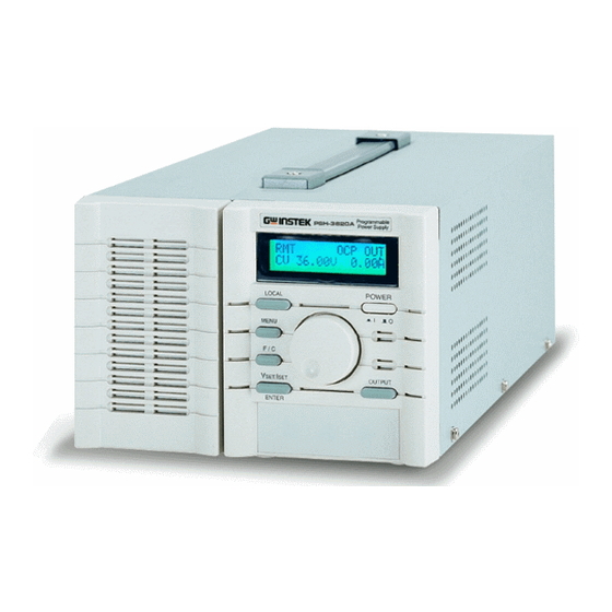
PST & PSS & PSH SERIES PROGRAMMABLE POWER SUPPLY
PST & PSS & PSH SERIES PROGRAMMABLE POWER SUPPLY
PROGRAMMER MANUAL
PROGRAMMER MANUAL
CONTENTS
PAGE
1. INTRODUCTION............................................................................. 1
2. CONNECTING POWER SUPPLY VIA GPIB INTERFACE.. 1
3. CONNECTING POWER SUPPLY VIA RS232 INTERFACE 4
4. INPUT AND OUTPUT QUEUE...................................... 7
5. COMMANDS AND SYNTAX........................................ 7
6. DETAILS OF COMMAND REFERENCE........................ 19
7. STATUS AND ERROR REPORTING............................... 38
⎯ i ⎯
⎯ ii ⎯
Advertisement
Table of Contents


Need help?
Do you have a question about the PST Series and is the answer not in the manual?
Questions and answers