Table of Contents
Advertisement
Quick Links
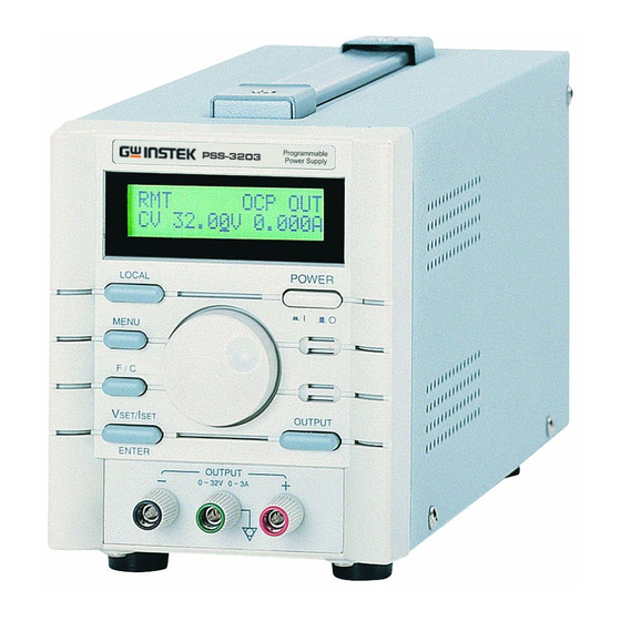
PSS-3203/2005 PROGRAMMABLE POWER SUPPLY
USER MANUAL
CONTENTS
1.
PRODUCT INTRODUCTION.................................................
1-1. Description......................................................
1-2. Feature............................................................
2.
TECHNICAL SPECIFICATIONS.............................. 3
3.
PRECAUTIONS BEFORE OPERATION......................
3-1. Unpacking the Instrument....................................
3-2. Checking the Line Voltage....................................
3-3. Environment.....................................................
4.
PANEL INTRODUCTION......................................... 7
5.
OPERATION METHOD...........................................
5-1. Output Voltage/Current Setting.............................
5-2. Over Voltage/Current Protection Setting..................
5-3. The Display Contrast Setting.................................
5-4. The Buzzer Setting.............................................
5-5. GPIB/RS-232 Interface Setting..............................
5-6. The Maximum Setting Value.................................
5-7. Test Lead.........................................................
6.
MAINTENANCE....................................................
6-1. Fuse Replacement..............................................
6-2. Line Voltage Conversion......................................
6-3. Adjustment and Calibration.................................
6-4. Cleaning.........................................................
7.
THE SYSTEM DIAGRAM AND DESCRIPTION...........
7-1.Block Diagram...................................................
7-2.The Operation of the whole circuit...........................
⎯
i
PAGE
1
1
1
5
5
5
6
10
10
11
12
12
12
13
13
13
14
14
14
15
18
19
19
20
⎯
PSS-3203/2005 PROGRAMMABLE POWER SUPPLY
USER MANUAL
SAFETY TERMS AND SYMBOLS
These terms may appear in this manual or on the product:
WARNING. Warning statements identify condition or
practices that could result in injury or loss of life.
CAUTION. Caution statements identify conditions or
practices that could result in damage to this product or
other property.
The following symbols may appear in this manual or on the product:
DANGER
ATTENTION
Protective
High Voltage
refer to Manual
Conductor
Terminal
⎯
ii
Earth (ground) Frame or Chassis
Terminal
Terminal
⎯
Advertisement
Table of Contents

Summary of Contents for GW Instek PSS-3203
-
Page 1: Table Of Contents
PSS-3203/2005 PROGRAMMABLE POWER SUPPLY PSS-3203/2005 PROGRAMMABLE POWER SUPPLY USER MANUAL USER MANUAL SAFETY TERMS AND SYMBOLS CONTENTS PAGE PRODUCT INTRODUCTION..........These terms may appear in this manual or on the product: 1-1. Description……………………………………………… 1-2. Feature…………………………………………………... TECHNICAL SPECIFICATIONS………………………… 3 WARNING. Warning statements identify condition or PRECAUTIONS BEFORE OPERATION…….…………... - Page 2 PSS-3203/2005 PROGRAMMABLE POWER SUPPLY PSS-3203/2005 PROGRAMMABLE POWER SUPPLY USER MANUAL USER MANUAL This cable/appliance should be protected by a suitably rated and FOR UNITED KINGDOM ONLY approved HBC mains fuse: refer to the rating information on the equipment and/or user instructions for details. As a guide, cable of 0.75mm...
-
Page 3: Product Introduction
PSS-3203/2005 PROGRAMMABLE POWER SUPPLY PSS-3203/2005 PROGRAMMABLE POWER SUPPLY USER MANUAL USER MANUAL 1. PRODUCT INTRODUCTION Declaration of Conformity 1-1.Description PSS-series Programmable Power Supply is controlled by Micro GOOD WILL INSTRUMENT CO., LTD. No. 7-1, Jhongsing Rd., Tucheng City, Taipei County 236, Taiwan Processor Unit (MPU) that can easily connect communication interface GOOD WILL INSTRUMENT (SUZHOU) CO., LTD. -
Page 4: Technical Specifications
PSS-3203/2005 PROGRAMMABLE POWER SUPPLY PSS-3203/2005 PROGRAMMABLE POWER SUPPLY USER MANUAL USER MANUAL 2.TECHNICAL SPECIFICATIONS 4) The function of over voltage/current/temperature protection. 5) Intelligent control fan (Vary with different output power.) SPECIFICATIONS PSS-3203 PSS-2005 Voltage 0~32V×1 0~20V×1 6) Warning signal by the built-in Buzzer. -
Page 5: Precautions Before Operation
PSS-3203/2005 PROGRAMMABLE POWER SUPPLY PSS-3203/2005 PROGRAMMABLE POWER SUPPLY USER MANUAL USER MANUAL 3.PRECAUTIONS BEFORE OPERATION Interface RS232 (GPIB interface option) 3-1.Unpacking the Instrument Power Source AC100V, 120V, 220V±10%, 230V +10%/-6% 50/60Hz The product has been fully inspected and tested before shipping from the... -
Page 6: Environment
PSS-3203/2005 PROGRAMMABLE POWER SUPPLY PSS-3203/2005 PROGRAMMABLE POWER SUPPLY USER MANUAL USER MANUAL 4. PANEL INTRODUCTION 3-3.Environment The normal ambient temperature range of this instrument is from 0° to 40°C (32° to 104°F). To operate the instrument exceeding this specific temperature range may cause damage to the circuits of instrument. - Page 7 PSS-3203/2005 PROGRAMMABLE POWER SUPPLY PSS-3203/2005 PROGRAMMABLE POWER SUPPLY USER MANUAL USER MANUAL 1. Power Switch Connect the AC power, then press power switch. Display Indicate the setting of voltage/current value, output voltage/current value and the status of setting and output.
-
Page 8: Operation Method
PSS-3203/2005 PROGRAMMABLE POWER SUPPLY PSS-3203/2005 PROGRAMMABLE POWER SUPPLY USER MANUAL USER MANUAL 5. OPERATION METHOD Example: If want to set the current as 1.234A, first using the [F/C] knob to 5-1. Output Voltage/Current Setting switch the cursor to 1mA step and adjust the value to 34, then... -
Page 9: The Display Contrast Setting
PSS-3203/2005 PROGRAMMABLE POWER SUPPLY PSS-3203/2005 PROGRAMMABLE POWER SUPPLY USER MANUAL USER MANUAL complete the setting. --Over Current Protection Setting: Set to OCP SET window by pressing [MENU], Turn on/off the OCP with the wheel knob and press [ENTER]. If OCP is on, when... -
Page 10: Maintenance
(see Fig.4-2). Press [LOCAL] for 4 to 5 seconds interruptedly to appear Password input window (vary with different models: PSS-3203: 3203, PSS- WARNING. For continued fire protection. Replace fuse 2005: 2005), input the password number with the wheel knob, and... - Page 11 PSS-3203/2005 PROGRAMMABLE POWER SUPPLY PSS-3203/2005 PROGRAMMABLE POWER SUPPLY USER MANUAL USER MANUAL [Step 2.1] [F/C] button to switch over the input of 100mA range (100mA/step) or 1mA range (1mA/step). Now input the voltage value (Min) measured by DMM with the knob and press [ENTER].
-
Page 12: Cleaning
PSS-3203/2005 PROGRAMMABLE POWER SUPPLY PSS-3203/2005 PROGRAMMABLE POWER SUPPLY USER MANUAL USER MANUAL When above calibration steps has been confirmed correctly, switch 7. THE SYSTEM DIAGRAM AND DESCRIPTION the calibration selection window to SAVE window with the knob and 7-1. Block Diagram press [ENTER] to complete the whole calibration procedures. -
Page 13: 7-2.The Operation Of The Whole Circuit
PSS-3203/2005 PROGRAMMABLE POWER SUPPLY PSS-3203/2005 PROGRAMMABLE POWER SUPPLY USER MANUAL USER MANUAL 7-2.The Operation of the whole circuit The operation in C.C. Mode is similar to that in C.V. Mode. The Each output channel of PSS-series has a reference voltage circuit at MPU will send 2100 counts, 2.1A output current, to DAC, output through...


Need help?
Do you have a question about the PSS-3203 and is the answer not in the manual?
Questions and answers