Table of Contents
Advertisement
Quick Links
Advertisement
Table of Contents
Troubleshooting

Related Manuals for Topcon HiPer II


Summary of Contents for Topcon HiPer II
- Page 3 Part Number 7010-0982 Rev C December, 2010 All contents in this manual are copyrighted by Topcon. All rights reserved. The information contained herein may not be used, accessed, copied, stored, displayed, sold, modified, published, distributed, or otherwise reproduced without express written consent from Topcon.
- Page 4 ECO#3997...
-
Page 5: Table Of Contents
Calculating Absolute Positions ......1-3 Calculating Differential Positions ...... 1-3 Essential Components for Quality Surveying ..1-5 Conclusion ............1-6 HiPer II Receiver ............1-7 HiPer II Features ............1-9 Battery ............... 1-10 Inserting and Removing the Battery ....1-11 Charging the Battery ........... - Page 6 Configuring a Digital UHF Radio Modem ....3-4 Configuring the Receiver ..........3-7 Chapter 4 HiPer II Receiver Setup ........4-1 Receiver Setup ..............4-1 Step 1: Set up the Receivers ........4-1 Step 2: Measure Antenna Height ....... 4-4 Static Surveying for Base Stations ........
- Page 7 Receiver Specifications ........... A-1 General Details ............A-1 GPS Board Details ............ A-5 Bluetooth Module Details ......... A-7 Internal Topcon UHF Modem General Specification Details ..........A-7 Internal UHF Satel Modem Details ......A-8 Optional GSM/GPRS Module Details ...... A-9 Battery (BDC58) Specifications .......
- Page 8 Community of Europe Compliance ........C-5 European Community Declaration of Conformity with R&TTE Directive 1999/5/EC ....C-5 Declaration of Conformity with Regard to the R&TTE Directive 1999/5/EC WEEE Directive ............... C-8 Appendix D Warranty Terms ........... D-1 HiPer II Operator’s Manual...
-
Page 9: Preface
Manual without Topcon’s express written consent and may only use such information for the care and operation of the receiver. The information and data in this Manual are a valuable asset of Topcon and are developed by the expenditure of considerable work, time and money, and are the result of original selection, coordination and arrangement by Topcon. - Page 10 Topcon. Windows® is a registered trademark of Microsoft Corporation. The Bluetooth® word mark and logos are owned by Bluetooth SIG, Inc. and any use of such marks by Topcon is used under license. Other product and company names mentioned herein may be trademarks of their respective owners.
- Page 11 You may not assign or transfer the Software or this license without the express written consent of Topcon. This license is effective until terminated. You may terminate the license at any time by destroying the Software and Manual.
-
Page 12: Manual Conventions
Supplementary information that can have an affect on system operation, system performance, NOTICE measurements, or personal safety. Notification that an action has the potential to adversely affect system operation, system CAUTION performance, data integrity, or personal health. HiPer II Operator’s Manual viii... - Page 13 Manual Conventions Notification that an action will result in system damage, loss of data, loss of warranty, or personal WARNING injury. Under no circumstances should this action be DANGER performed. P/N 7010-0982...
- Page 14 Notes: HiPer II Operator’s Manual...
-
Page 15: Chapter 1 Introduction
The HiPer II can receive and process GNSS signals on the L1 and L2 frequencies of both the GPS and GLONASS satellite navigation systems. This multi-frequency and multi-constellation capability... -
Page 16: Principles Of Operation
These satellites broadcast ranging signals and various digital information (ephemerides, almanacs, time and frequency corrections, and so forth). • Control - Ground stations located around the Earth that monitor the satellites and upload data, including clock corrections and HiPer II Operator’s Manual... -
Page 17: Calculating Absolute Positions
Principles of Operation new ephemerides (satellite positions as a function of time), to ensure the satellites transmit data properly. • User - The community and military that use GNSS receivers to calculate positions. Calculating Absolute Positions When calculating an absolute position, a stationary or moving receiver determines its three-dimensional position with respect to the origin of an Earth-Center Earth-Fixed coordinate system. - Page 18 RTCM message formats (v3 or greater) for all RTK and DGPS communication needs. Several legacy correction message formats are also provided by Topcon GNSS products in order to support interoperability with older GNSS systems, but their use is now deprecated.
-
Page 19: Essential Components For Quality Surveying
RTK accuracy of up to 10mm horizontal and 15mm vertical. Essential Components for Quality Surveying Achieving quality positioning results from the HiPer II requires an understanding of the following elements: • Accuracy - The accuracy of a position that is delivered by a... -
Page 20: Conclusion
DGPS corrections, data integrity information (for example, satellite health warnings). – Current ephemerides and almanacs. Conclusion This overview simply outlines the basics of satellite positioning. For more detailed information, visit the Topcon website. HiPer II Operator’s Manual... -
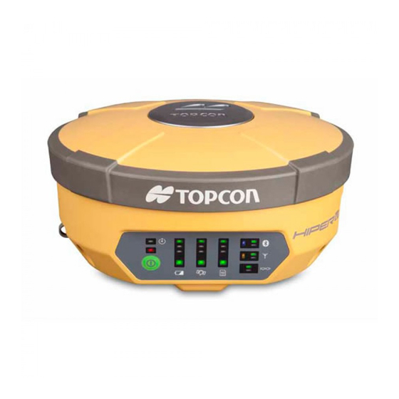
Page 21: Hiper Ii Receiver
Each of the receiver's channels can be used to track any one of the available GPS or GLONASS signals. The number of channels on the HiPer II allows the receiver to track all visible global positioning satellites at any time and location. - Page 22 Introduction Depending on your options, capabilities of the HiPer II receiver include: • Use of satellite-based augmentation systems (SBAS) such as WAAS/EGNOS/MSAS for improved positioning accuracy during autonomous operation. • Adjustable Phase Locked Loop (PLL) and Delay Lock Loop (DLL) parameters •...
-
Page 23: Hiper Ii Features
The HiPer II receiver’s advanced design reduces the number of cables required for operation, allowing for more reliable and efficient surveying. The HiPer II receiver includes one data port, a power port, an LED Display Panel for viewing the current receiver status, and also includes: •... -
Page 24: Battery
Introduction Battery The HiPer II receiver comes equipped with two detachable Li-Ion batteries (Figure 1-2) for powering the receiver and one CDC68 charger. The battery is capable of running for more than 7.5 hours on a single charge (only static observation). -
Page 25: Inserting And Removing The Battery
Principles of Operation Inserting and Removing the Battery • First, before removing the battery, always turn off power to the instrument. If the battery is removed while the power is switched on, uncontrolled system shutdown will occur and file data may be lost as a result. - Page 26 Introduction To Remove the Battery: 1. Turn the HiPer II over. 2. Push the battery buttons on both sides of the battery compartment cover, and lift the battery cover. Press and Hold Both Battery Compartment Buttons (One on Each Side) Figure 1-3.
-
Page 27: Charging The Battery
Principles of Operation To Insert the Battery: 1. Remove the battery cover. 2. Gently slide the bottom of the battery along the battery guides until it snaps into place (Figure 1-5 on page 1-13). Slide Battery to the Left to Lock in Place Figure 1-5. - Page 28 2. Mount the battery in the charger by matching the grooves on the battery with the guides on the charger. Figure 1-6. Insert Battery onto Charger 3. When charging begins, the lamp light blinks. 4. The lamp light is solid when charging is complete. HiPer II Operator’s Manual 1-14...
- Page 29 Principles of Operation 5. Remove the battery and unplug the charger. Figure 1-7. Remove Battery Slots 1 and 2: The charger starts charging the battery mounted NOTE first. If two batteries are placed in the charger, the battery in slot 1 is charged first, and then the battery in slot 2.
-
Page 30: Led Display Panel
Introduction LED Display Panel The HiPer II LED Display Panel is used to display and indicate the receiver’s current operational status. The display offers a compact but valuable summary of the most important receiver information for the typical user. Position Status Bar... - Page 31 Less than 10% Less than 6.5V indicates the currently available power sources Battery Status LED for the HiPer II. BATTERY STATUS Only the internal battery is available. Only external power is available. Both the battery and external power are available.
- Page 32 Introduction indicates the number and type of satellites currently being STAT LED tracked by the HiPer II. TRACKING STATUS (STAT) ORDER DISPLAY STATUS Blink per tracked GPS satellite. Blink per GPS satellite with <48dB signal strength. Blink per tracked GLONASS satellite.
- Page 33 Principles of Operation indicates the status of the current file. File Status LED FILE STATUS Communication Status LEDs Wireless Status LEDs indicate the status of the internal Bluetooth module. Radio Status LEDs indicate the status of the internal UHF radio and GSM module. Serial Port Status LEDs indicate the status of the serial port.
- Page 34 The file is opened by the JOB. The file is closed by the JOB. When the HiPer II is powered off and a timer JOB is in waiting, the timer LED blinks once every two seconds momentarily. performs multiple functions. The number of seconds...
-
Page 35: Audible Annunciator
Figure 1-9. Raw Data Collection using the Power Button Audible Annunciator The HiPer II receiver is equipped with a voice notification feature that issues a series of voice messages and sounds to alert the user to different system status’ and event conditions. -
Page 36: Data And Power Ports
DISCONNECT Bluetooth has been disconnected Data and Power Ports The HiPer II has the two ports described below (Figure 1-10 on page 1-23): • Serial - rimmed in black; used for communication between the receiver and an external device. The body of the connector on the corresponding cable is black. -
Page 37: External Radio Antenna Connector
The antennas for the receiver’s internal UHF radio (and optional cellular modem) connect to the BNC external antenna connector located under the HiPer II housing (Figure 1-11). The optimal modem antenna depends on the frequency of the UHF radio that is installed in the receiver: •... -
Page 38: Connector
SD/SDHC card can be accessed by removing the card and using an external SD/SDHC card reader, or by using Topcon PC software to download the data from the card via HiPer II’s serial port or Bluetooth connection. A secure digital card suitable for industrial use can be purchased from a local Topcon dealer. - Page 39 SIM Card Slot SD/SDHC Card Slot Figure 1-13. HiPer II Card Slot Example Once installed, the card(s) generally remains installed. The card can then be accessed via the receiver board using a data port or Bluetooth connection.
- Page 40 Circuit Switch Data plan and have subscriptions to the same service provider for proper data communication. 1. Ensure the receiver is turned off. 2. Remove the battery. 3. If needed, snap the SIM card into its holder. HiPer II Operator’s Manual 1-26...
-
Page 41: Serial Cable
Once the receiver is turned on, the receiver board will detect the SIM card, and it will be ready to use as needed. Serial Cable The HiPer II package includes a serial communication cable for configuring the receiver. Table 1-2 describes the cable included in the HiPer II package. -
Page 42: Other Accessories
Topcon offers a wide variety of accessories especially designed to improve system flexibility and jobsite efficiency. For more details on the optional accessories available for HiPer II, contact a local Topcon dealer. • Radio Antenna for Digital modem 410-470Hz (30-070003-01 or 30-050503-01) •... -
Page 43: Option Authorization File (Oaf)
The OAF enables the following kinds of functions. For a complete list of available options and details for HiPer II, visit the Topcon website or consult a Topcon dealer. • Type of signal (standard L1 GPS; optional L2, GPS, GLONASS) •... - Page 44 Introduction Notes: HiPer II Operator’s Manual 1-30...
-
Page 45: Pre-Survey Preparation
Chapter 2 Pre-survey Preparation Before beginning to survey with the HiPer II receiver, install the following software, charge the battery, and apply the following configurations: Install receiver configuration software See “Installing Topcon Software” on page 2-2. Optional: install SD/SDHC card and/or SIM card See “Install the Optional SD/SDHC and SIM Cards”... -
Page 46: Installing Topcon Software
Pre-survey Preparation Installing Topcon Software The GPS+ Software CD includes the TRU (Topcon Receiver Utility) software. If installing TRU from the GPS+ Software CD, insert the CD into the computer’s CD/DVD-ROM drive. If downloading TRU from the website, extract the program’s files into a folder on the hard drive. -
Page 47: Install The Optional Sd/Sdhc And Sim Cards
See “SD/SDHC and SIM Card NOTICE Slots” on page 1-24. Charge and Insert the Battery Ensure the is fully charged and inserted into the HiPer II’s battery recess. See “Inserting and NOTICE Removing the Battery” on page 1-11. Connecting to the Receiver using TRU TRU provides an interface for various configuration, monitoring, and management functions for the receiver. -
Page 48: Establishing A Serial Cable Connection
To establish a connection to the receiver, press the Connect button. When detecting the receiver, the Detecting Receiver dialog box displays. Figure 2-2. Stages for Connecting the Receiver via Serial Cable 6. To close the serial connection to the receiver, click Device Disconnect: HiPer II Operator’s Manual... -
Page 49: Establishing A Wireless Connection
Connecting to the Receiver using TRU To successfully connect to the HiPer II receiver, do not check the External Receiver checkbox in the NOTE Connection Parameters dialog box. Establishing a Wireless Connection The HiPer II receiver contains Bluetooth wireless technology that allows file transfer and synchronization between the receiver and any other external device that supports Bluetooth wireless technology;... - Page 50 Select Port dialog box and click OK. To establish the connection to the receiver, press the Connect button in the Connection Parameters dialog box. When detecting the receiver, the Detecting Receiver dialog box displays (Figure 2-4 on page 2-7). HiPer II Operator’s Manual...
-
Page 51: Collecting Almanacs And Ephemerides
Collecting Almanacs and Ephemerides Figure 2-4. Stages for Connecting to the Receiver via Bluetooth 6. To close the connection to the receiver, click Device Disconnect: Collecting Almanacs and Ephemerides Each satellite broadcasts a navigation message that includes the ephemeris parameters of the satellite, the almanac, and various other information. -
Page 52: Powerup Script
• After loading new firmware. • After clearing the NVRAM. POWERUP Script The HiPer II’s POWERUP script feature uses specially formatted enables the receiver ASCII text file (GRIL commands) that, once installed, to perform a series of custom operations simply by pressing the power button to turn on the receiver. -
Page 53: Example
No cabling, external data link, or data collector is required; work on site can begin almost immediately. POWERUP Script Requirements After turning on the HiPer II receiver, the POWERUP script executes when the receiver obtains valid position coordinates and the following requirements are satisfied. -
Page 54: Uninstall The Powerup Script
Enabling the POWERUP Script It is necessary to enable the POWERUP script function in order to allow the HiPer II to execute the POWERUP script at every startup of the receiver. Enable the POWERUP script by using any of the following three methods. - Page 55 POWERUP Script Disabling POWERUP Script Disable the POWERUP script by using either of the following two methods. Send the terminal command “set,/ext/powerup/mode,off” Method 1: Disable by using the TRU software. Method 2: P/N 7010-0982 2-11...
- Page 56 Pre-survey Preparation Notes: HiPer II Operator’s Manual 2-12...
-
Page 57: Hiper Ii Configuration
Set up the Base receiver over a known point to begin collecting static observation data and transmitting RTK corrections. Set up the Rover receiver to begin collecting RTK data. See “HiPer II Receiver Setup” on page 4-1 for more information. -
Page 58: Managing The Radio Modem
HiPer II Configuration Managing the Radio Modem Topcon’s TRU software supports the configuration of all radio modems that are embedded in Topcon receivers. To configure the radio modem, have the following ready: • PC running Windows 2000 or newer • TRU •... - Page 59 4. Select the COM Port the receiver is connected to. Click OK. Figure 3-2. Select COM Port 5. All internal modems for the HiPer II are on port C. Select the Internal Modem check box and choose ser/c from the drop-down menu.
-
Page 60: Configuring A Digital Uhf Radio Modem
25cm between the user and the NOTICE radio modem. 1. On the TRU Main Screen in Modem Managing mode double- click on the Settings icon to configure the HiPer II internal modem. Figure 3-5. Modem Managing HiPer II Operator’s Manual... - Page 61 Managing the Radio Modem 2. If the user has a Digital UHF modem (other name Digital AW401), this screen will appear as the General tab to show information on the modem model, and the product identification Figure 3-6. Modem General Information 3.
- Page 62 (must be used with GMSK). • FEC – (Forward Error Correction) Enable to maximize data link reliability. The rover radio modem has the capability to check and correct transmission errors (if any) in an incoming data stream. HiPer II Operator’s Manual...
-
Page 63: Configuring The Receiver
If needed, launch TRU and set up the receiver to run as an RTK Base station or RTK Rover. Configuring the Receiver The HiPer II can be configured in several ways for collecting data for RTK or post-processing. • A static Base station collects measurement information and saves this data to its internal memory. - Page 64 HiPer II Configuration • a Bluetooth-enabled external device (computer) • an RS232 cable TRU is Topcon’s GNSS receiver configuration software. For more information on any of the procedures in this section or on TRU, refer to the TRU Reference Manual.
- Page 65 Configuring the Receiver Once a TRU connection with the receiver has been established, the Tools become active (Figure 3-8). Figure 3-8. TRU Connection Established 2. Select the Receiver Settings icon. Then use the Receiver Settings icons to configure the connected receiver. Figure 3-9.
- Page 66 (Figure 3-11), also the PDOP mask for position computation, then click OK. Figure 3-11. Configure Receiver Positioning – Elevation Mask 5. Click the Advanced tab. Set the following parameters, and click OK (Figure 3-12 on page 3-11). HiPer II Operator’s Manual 3-10...
- Page 67 Configuring the Receiver • Anti-jamming – if available for the connected receiver, enables suppression of narrow-band interference for GPS, GLONASS, L1, L2 signals, for auto-detected or manually selected bands affected by interference. • C/A code multipath reduction – when selected, enables the use of a special signal processing technique for reduction of C/A code phase multipath.
- Page 68 For details on configuring the Auto Seed functionality, refer to the TRU Reference Manual. 7. For the Rover receiver, click the Positioning icon, and set the following parameters, then click OK (Figure 3-14 on page 3-13). HiPer II Operator’s Manual 3-12...
- Page 69 Configuring the Receiver • Positioning Mode – For post-processed surveys, select Standalone; for RTK surveys, select RTK float or RTK fixed. • Enable Solutions – Select solutions used in position computation. – Standalone – where the receiver computes 3D coordinates in autonomous mode without using differential corrections.
- Page 70 • Data link quality in percentage • Time (in seconds) elapsed since the last received message • Total number of received correct messages (dependent on the message type received) HiPer II Operator’s Manual 3-14...
- Page 71 Configuring the Receiver • Total number of received corrupt messages (dependent on the message type received) If the receiver is (for some reason) not receiving differential corrections, or if none of the ports have been configured to receive differential corrections, the Link Quality field will either be empty or it will show 0%.
- Page 72 HiPer II Configuration Notes: HiPer II Operator’s Manual 3-16...
-
Page 73: Hiper Ii Receiver Setup
Chapter 4 HiPer II Receiver Setup After receiver survey configuration, set up each receiver, measure its height, and begin surveying. The LED Display Panel provides quick access for: logging data and viewing general data logging and satellite information during a survey. - Page 74 3. Insert the horizontal spacer into the precision tribrach adapter. 4. Attach the 10cm spacer to the horizontal spacer. 5. Attach the HiPer II receiver to the 10cm spacer. 6. Attach the antenna to the antenna connector. 7. Carefully level the tripod and tighten the screws.
- Page 75 NOTICE logging. Attach the HiPer II receiver to the top of the rover pole with 5/8”x11” thread. Make sure that the receiver is securely affixed to the top of the rover pole. HiPer II Receiver...
-
Page 76: Step 2: Measure Antenna Height
For precision Topcon GPS/GLONASS antennas − such as the one inside the HiPer II − the antenna Phase Center must be modeled using a detailed calibration in order to achieved optimal survey results. - Page 77 1. Advanced users may choose to configure the applied Phase Center model that is used for the Hiper II, and this may be done using Topcon application software such as TopSURV and Topcon Tools. This additional step is optional since Topcon software automatically contains antenna Phase Center models for all Topcon products, including the Hiper II.
- Page 78 HiPer II Receiver Setup Figure 4-3. Antenna Height Measurement Points HiPer II Operator’s Manual...
-
Page 79: Static Surveying For Base Stations
Static Surveying for Base Stations Static Surveying for Base Stations Static surveying is the classic survey method, well suited for all kinds of baselines (short, medium, long). At least two receiver antennas, plumbed over survey marks, simultaneously collect raw data at each end of a baseline during a certain period of time. - Page 80 HiPer II Receiver Setup Notes: HiPer II Operator’s Manual...
-
Page 81: Receiver And File Maintenance
The various boards inside the receiver (GPS, power, modem, and Bluetooth) require firmware to properly operate and provide appropriate functionality. As Topcon releases firmware updates, loading these updates into the receiver will ensure the receiver operates at its full potential. - Page 82 Download from the pop up menu. In the Save As dialog box navigate to or create a folder in which to download and store the file (Figure 5-2). Click the Save button to download and save the file. Figure 5-2. Download a File HiPer II Operator’s Manual...
-
Page 83: Deleting Files From The Receiver Using Tru
Deleting Files from the Receiver Using TRU 4. When the process of transferring the file(s) from the receiver to the computer begins, the Downloading window displays the progress of the download. Figure 5-3. Downloading in Progress Deleting Files from the Receiver Using TRU To delete files from the receiver, perform steps 1and 2 described in “Downloading Files to a Computer”... -
Page 84: Using The Power Button To Deleting Files
• The type of signal (L1, L1/L2, and so on) the receiver processes. • The amount of data the receiver stores in the memory. • The rate at which data is transmitted or received. For a complete list of available options and details, consult with a Topcon dealer. HiPer II Operator’s Manual... -
Page 85: Checking The Receiver's Oaf
Figure 5-5. Receiver Options Loading an OAF Topcon dealers provide customers with OAF files. For any OAF related questions, e-mail Topcon at options@topcon.com and include the receiver’s ID number (see the bottom of the receiver for the ID). - Page 86 Open (Figure 5-6). Figure 5-6. Load OAF 4. Topcon TRU initially checks to see if the selected file is compatible with the currently connected receiver. If the user chose a file not intended for this receiver, the Upload OAF dialog...
-
Page 87: Loading New Firmware
• ramimage.ldr – the Receiver board RAM file • main.ldp – the Receiver board Flash file To upload firmware files to HiPer II receiver, follow the steps below: 1. Connect the receiver to a computer. Open TRU. See “Connecting to the Receiver using TRU” on page 2-3 for this procedure. -
Page 88: Clearing The Nvram
Even though clearing the NVRAM is not a common (nor normally a recommended) operation, there are times when clearing the NVRAM HiPer II Operator’s Manual... -
Page 89: Using Tru To Clear The Nvram
Clearing the NVRAM can eliminate communication or tracking problems. Clearing the receiver’s NVRAM can be interpreted as a “soft boot” in the computer. After clearing the NVRAM, the receiver requires time to collect new ephemerides and almanacs (around 15 minutes). Clearing the receiver’s NVRAM will not delete any files already recorded in the receiver’s memory. - Page 90 Receiver and File Maintenance Notes: HiPer II Operator’s Manual 5-10...
-
Page 91: Chapter 6 Troubleshooting
• Check that the most current software is downloaded onto the computer and that the most current firmware is loaded into the receiver. Check the Topcon website for the latest updates. Then, try the following: • Reset the receiver using TRU (Tools Reset receiver). -
Page 92: Troubleshooting Quick List
All receivers are preset in the factory to “Auto mode” for the battery. To check these settings, use the following procedure: 1. Connect the receiver and a computer and run TRU (see “Connecting to the Receiver using TRU” on page 2-3). 2. Once connected, click Configuration Receiver. HiPer II Operator’s Manual... - Page 93 • Check that the cable is securely connected and undamaged. The receiver may have a defective charger or defective battery. • If, after changing the battery or connecting an external power source, the receiver still does not power up, contact Topcon Customer Support for advice. P/N 7010-0982...
-
Page 94: Receiver Problems
• Check that the cable connector is attached to the correct receiver port. • Unplug the cable, then securely and properly reconnect it to the receiver. • See “HiPer II Features” on page 1-9 and “Power Connector” on page A-12 for information on the receiver’s connectors. The cable is damaged. - Page 95 • Order a new OAF with the desired options activated to enable or extend validity of the corresponding receiver options. Contact a dealer or visit the Topcon website for details • Refer to the TRU Reference Manual for a detailed description of options.
- Page 96 • Order a new OAF with the required options activated to enable or extend validity of the corresponding receiver options. Contact a dealer or visit the Topcon website for details • Refer to the TRU Reference Manual for a detailed description of options.
- Page 97 Receiver Problems The specified baud rate is incompatible with the baud rates the modem supports. The baud rate is the rate at which the receiver transmits differential messages to the modem and vice versa. • Change the baud rate to that which the modem supports. Refer to the modem’s manual for information.
-
Page 98: Bluetooth Problems
If using a cable, the cable is damaged. • Use an undamaged cable. • Contact a Topcon dealer to purchase a new cable. The COM port the receiver is attached to differs from the one selected in TRU. - Page 99 • Order a new OAF with the required options activated to enable or extend validity of the corresponding receiver options. Contact a dealer or visit the Topcon website for details • Refer to the TRU Reference Manual for a detailed description of options.
-
Page 100: Tru Problems
The following is the most commonly encountered TRU problem. TRU cannot connect to the receiver The receiver is turned off. • Ensure the receiver has power and is turned on. If using a cable, the cable’s connectors are improperly attached. HiPer II Operator’s Manual 6-10... - Page 101 • Check that the computer and receiver use the correct ports for communication. For the HiPer II receiver, this is port A. The corresponding modem options may be disabled or expired. • See “Managing Receiver Options” on page 5-4 for details on how to check current options.
-
Page 102: Obtaining Technical Support
To contact Topcon Customer Support by phone, call: • 1-800-4-Topcon or 1-800-476-5542 • 1-866-4-Topcon or 1-866-486-7266 Email To contact Topcon Customer Support via email, use one of the following electronic mail addresses (Table 6-1). Table 6-1. Technical Support Email For Questions Related To... -
Page 103: Website
Generally, a customer support representative will reply within 24 hours, depending on the severity of the problem. Website The Topcon website provides current information about Topcon’s line of products. The support area of the website provides access to frequently asked questions, configuration procedures, manuals, e- mail support, and so forth. - Page 104 Troubleshooting Notes: HiPer II Operator’s Manual 6-14...
-
Page 105: Appendix A Specifications
Appendix A Specifications The HiPer II receiver is a 72-channel GNSS receiver with an internal radio modem, a Bluetooth wireless technology module, an optional GSM module, an optional, removable SD/SDHC memory card, and a rugged magnesium housing complete with an LED Display Panel and cable connectors. - Page 106 Battery charging 4 hours time Operating time Over 7.5 hours (20C / Only static tracking / w BT) External power 1 port Input voltage 6.7 to 18VDC Consumption 4W (w/o UHF modem) Battery charge Use CDC68 HiPer II Operator’s Manual...
- Page 107 Receiver Specifications Table A-1. Receiver General Specifications (Continued) On-board Backup battery for NVRAM and RTC storage; Operation for approximately 100 days. Communication Bluetooth x (Serial) RS-232C x 11 Ports Port specifications COM1: 4,800 to 115,200 bps (RS Level) 115,200bps (default) Bluetooth: 115,200bps (SPP/Single Channel mode) Modem Antenna BNC or reverse polarity TNC (depending on modem...
- Page 108 H: 10mm+1 ppm RMS V: 15mm+1 ppm RMS L1/L1 +L2: H: 10mm + 1 ppm RMS; V: 15mm + 1 ppm RMS DGPS Post processing/RTCM: Typically less than 0.5m RMS Cold start <40sec Warm start <20sec(typical) Reacquisition <1sec HiPer II Operator’s Manual...
-
Page 109: Gps Board Details
Table A-2 lists the GPS board’s general specifications. Table A-2. GPS Board Specifications Receiver Type (set by activating the proper OAF) Internal board: G: GPS L1 HiPer II GD: GPS L1/L2 GG:GPS/GLONASS L1 GGD: GPS/GLONASS L1/L2 Hardware type: with Digital UHF... - Page 110 Different DATUMs support Output of grid coordinates CMR and CMR+ support Memory Internal Memory SD/SDHC card, removable Capacity Dependent on capacity of the installed SD/SDHC card Logging Interval 0.05 to 86,400 seconds, depending on purchased options HiPer II Operator’s Manual...
-
Page 111: Bluetooth Module Details
Frequency Country North America and Europe Code Internal Topcon UHF Modem General Specification Details Table A-4 lists the Digital UHF modem’s general specifications. Table A-4. HiPer II Digital UHF Modem General Specifications Parameter Specification Operating frequency range 410-470 MHz country/region/purpose dependent... -
Page 112: Internal Uhf Satel Modem Details
9600 bps (12.5 kHz channel) Data format Asynchronous Transmitter (TX) Carrier power 10mW–1W/50 ohms Carrier power +2dB / -3 dB stability Adjacent channel according to EN 300 220-1/ETS 300 113 power Spurious radiations according to EN 300 220-1/ETS 300 113 HiPer II Operator’s Manual... -
Page 113: Optional Gsm/Gprs Module Details
Receiver Specifications Table A-5. Internal UHF Satel Modem Specifications (Continued) Receiver (RX) Sensitivity -116...-110 dBm (BER<10 E-3) Common channel >-12dB rejection Adjacent channel >60 dB @ 12.5 kHz selectivity >70 dB @ 25 kHz Intermodulation > 65 dB attenuation Spurious radiation <2nW Optional GSM/GPRS Module Details Table A-6 lists the internal general specifications for the internal modem... -
Page 114: Battery (Bdc58) Specifications
Charging 0°C to 40°C (32°F to 104°F) temperature range: Storage temperature -20°C to 65°C (-4°F to 149°F) range: Size: 94 (W) X 102 (D) X 36 (H) mm Weight: about 170g HiPer II Operator’s Manual A-10... -
Page 115: Connector Specifications
Connector Specifications Connector Specifications The HiPer II has 3 external connectors; one UHF radio modem connector, one power connector, and one serial port connector. Table A-9, Table A-10 on page A-12, and Table A-11 on page A-13 list the specifications for the external connectors. -
Page 116: Power Connector
Rimmed in red, the power connector (Figure A-1) is a 5 pin sealed receptacle. Figure A-1. Power Connector Table A-10 gives power connector specifications. Table A-10. Power Connector Specifications Number Signal Name Details Input Power_INP Power_GND Ground, power return Not used Not used Not used HiPer II Operator’s Manual A-12... -
Page 117: Serial Rs232 Connector
Connector Specifications Serial RS232 Connector Rimmed in black, the serial RS232 connector (Figure A-2) is a sealed receptacle, 7 pin, ODU part number G80F1C-T07QC00-0000. Figure A-2. Serial RS232 Connector (ODU) Table A-11 gives the RS232 connector specifications. Table A-11. RS232 Connector Specifications Number Signal Name Details... - Page 118 Specifications Notes: HiPer II Operator’s Manual A-14...
-
Page 119: Appendix B Safety Warnings
To comply with RF exposure requirements, maintain at least 25cm between the user and the NOTICE radio modem. Topcon receivers are designed for survey and survey related uses (that is, surveying coordinates, distances, angles and depths, and recording such WARNING measurements). -
Page 120: Battery Pack Warnings
• Do not disassemble the battery pack. • Do not charge in conditions different than specified. • Do not use other than the specified battery charger. • Do not short circuit. • Do not crush or modify. HiPer II Operator’s Manual... -
Page 121: Usage Warnings
The owner should periodically test this product to ensure it provides accurate measurements. Inform Topcon immediately if this product does not function properly. Only allow authorized Topcon warranty service centers to service or repair this product. - Page 122 Safety Warnings Notes: HiPer II Operator’s Manual...
-
Page 123: Regulatory Information
Appendix C Regulatory Information The following sections provide information on this product’s compliance with government regulations for use. UHF Radio Usage Using a UHF radio requires a license. Operating a UHF radio without a license may result in fines or NOTICE other penalties. -
Page 124: Fcc Compliance
Regulatory Information • Check the Topcon accessory line for items to raise the Base radio. FCC Compliance This equipment complies with FCC radiation exposure limits set forth for uncontrolled equipment and meets the FCC radio frequency (RF) Exposure Guidelines in Supplement C to OET65. This equipment has very low levels of RF energy that it deemed to comply without maximum permissive exposure evaluation (MPE). -
Page 125: Federal Communication Commission Declaration Of Conformity (Doc) Statement
CAUTION compliance could void your authority to operate such equipment. Federal Communication Commission Declaration of Conformity (DoC) Statement Model No: HiPer II Trade Name Topcon Responsible Party Topcon Positioning Systems, Inc. 7400 National Drive,... -
Page 126: Ic Rf Radiation Exposure Statement
2.4dB. Antennas not included in this or having a gain greater than 2.4 dB are strictly prohibited for use with this device. The required antenna impedance is 50 ohms. • HiPer II/U 2.4dBi whip antenna Manufacture/Type 410-440MHz ANTENEX/G420BN 440-470MHz CENTURION/EVR450 HiPer II Operator’s Manual... -
Page 127: Community Of Europe Compliance
Community of Europe Compliance Community of Europe Compliance The product described in this manual is in compliance with the R&TTE and EMC directives from the European Community. European Community Declaration of Conformity with R&TTE Directive 1999/5/EC The following standards were applied: (R&TTE Directive 1999/5/EEC) •... - Page 128 Regulatory Information Declaration of Conformity with Regard to the R&TTE Directive 1999/5/EC (Topcon) tímto prohlašuje, že tento (HiPer II) je ve esky shod se základními požadavky a dalšími píslušnými [Czech] ustanoveními smrnice 1999/5/ES. Undertegnede (Topcon) erklærer herved, at Dansk følgende udstyr (HiPer II) overholder de væsentlige [Danish] krav og øvrige relevante krav i direktiv 1999/5/EF.
-
Page 129: Declaration Of Conformity With Regard To The
(Topcon) declara que este (HiPer II) está conforme Portuguê com os requisitos essenciais e outras disposições da Directiva 1999/5/CE. [Portugues] (Topcon) izjavlja, da je ta (HiPer II) v skladu z Slovensk bistvenimi zahtevami in ostalimi relevantnimi doloili direktive 1999/5/ES. [Slovenian] (Topcon) týmto vyhlasuje, že (HiPer II) spa... - Page 130 Suomi laite on direktiivin 1999/5/EY oleellisten [Finnish] vaatimusten ja sitä koskevien direktiivin muiden ehtojen mukainen. Härmed intygar (Topcon) att denna (HiPer II) står Svenska I överensstämmelse med de väsentliga [Swedish] egenskapskrav och övriga relevanta bestämmelser som framgår av direktiv 1999/5/EG.
- Page 131 Declaration of Conformity with Regard to the R&TTE P/N 7010-0982...
-
Page 132: Weee Directive
For more detailed information about the take-back and recycling of this product, please contact a supplier where you purchased the product or consult. HiPer II Operator’s Manual C-10... -
Page 133: Appendix D Warranty Terms
1. The warranty against defects in a Topcon battery, charger, or cable is 90 days. P/N 7010-0982... - Page 134 Warranty Terms Notes: HiPer II Operator’s Manual...
- Page 135 GNSS, definition GPRS, and SIM card 1-26 GPS board Cables 1-27 GSM usage Checklist GSM/GPRS module PP survey configuration specifications pre-survey receiver setup RTK survey configuration connecting HiPer II Kit Connector 1-24 setup Base P/N 7010-0982 P/N 7010-0982 Index Index...
- Page 136 1-26 Software 1-29 specifications update almanac Static survey Offsets Static survey, definition internal antenna Surveying Option authorization file static See OAF System range Ports Test Serial 1-22 Power 1-22 disconnect Power connector save settings HiPer II Operator’s Manual Index...
- Page 137 Index UHF radio modem connector specifications A-11 UHF Satel modem specifications UHF usage Voice notification 1-21 Warnings battery pack general usage Wireless connection P/N 7010-0982 Index...
- Page 138 Notes: HiPer II Operator’s Manual Index...
Need help?
Do you have a question about the HiPer II and is the answer not in the manual?
Questions and answers