Table of Contents
Advertisement
Quick Links
Advertisement
Table of Contents

Related Manuals for Topcon HiPer VR


Summary of Contents for Topcon HiPer VR
- Page 1 HiPer VR GNSS Receiver Operator’s Manual...
- Page 2 GNSS Receiver Operator’s Manual Part Number 1023998-01 Rev A © Copyright Topcon Positioning Systems, Inc. September 2018 For more information contact Synergy Positioning Systems or visit the Synergy Positioning Systems website at www.synergypositioning.co.nz All branches: Phone 0800 867 266 Email: info@synergypositioning.co.nz...
-
Page 3: Table Of Contents
Technical Documents ..........1-4 Using Topcon Software With Your Receiver ......1-4 Getting Technical Support . - Page 4 Setting Up the Rover Receiver ........6-2 Using HiPer VR with External Antenna ......6-4 Measuring Antenna Height .
- Page 5 Specifications ..........9-1 General Details .
-
Page 6: Preface
Preface Thank you for purchasing this Topcon product. The materials available in this Manual (the “Manual”) have been prepared by Topcon Positioning Systems, Inc. (“TPS”) for owners of Topcon products, and are designed to assist owners with the use of the receiver and its use is subject to these terms and conditions (the “Terms and Conditions”). - Page 7 On the Topcon Support website (www.topconpositioning.com/support), you can download manuals, technical documentation, training material, and various utility software to help you set up and use your Topcon product. The website also offers registration resources, training, and technical assistance. Register for a free account at https://www.topconpositioning.com/support today to download this material.
- Page 8 , and click guest Mono Italic Topcon Reference Manual. Reference to another manual or help document Refer to the Further information to note about system configuration, maintenance, or setup. Supplementary information that can have an adverse affect on system operation, system performance, data integrity, or measurements.
-
Page 9: Introduction
MAGNET Field for calculating the true projection of the rover antenna phase center on the ground. The HiPer VR GNSS Receiver offers complete IP67 protection against dust and water ingress, in addition to superior vibration and shock resistance. The Topcon communication interface allows you to integrate GNSS performance and quickly deliver world class positioning and navigation support to your applications. -
Page 10: Hiper Vr Features
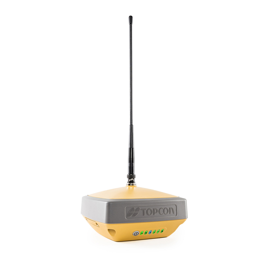
Figure 1-1: HiPer VR Receiver HiPer VR Features The HiPer VR GNSS receiver’s advanced design allows for simplified setup and maximum performance. The HiPer VR receiver features the following: • 226 GNSS channel Vanguard Technology™ with Universal Tracking Channels for multi- frequency tracking of multiple satellite constellations such as GPS, GLONASS, BeiDou, QZSS, SBAS, and Galileo. -
Page 11: Unpacking Your Receiver Kit
For more details on the optional accessories available for HiPer VR, contact your Topcon dealer. 1. Components in the standard kits may differ based on your country or region. Contact your local Topcon dealer to inquire about items included in your regional standard kit and accessories that are available with the receiver. -
Page 12: Technical Documents
Table 1-2 lists the accessories available for the HiPer VR. For more information about accessories, see “Accessories”. Table 1-2. HiPer VR Accessories Radio Antenna Prism External Antenna Cable Fixed Height Heavy Duty Tripod Rover Pole Offset Adapters Economy Tripod Tribrach with Plug Adapter... -
Page 13: Getting Technical Support
Getting Technical Support Before contacting a Topcon customer representative about any problems with the receiver, see “Troubleshooting” for some solutions that may fix the issue. Contact your local Topcon dealer or visit the Topcon TotalCare support site (https://www.topconpositioning.com/support) for technical support For quick and effective support, provide a detailed description of the problem. -
Page 14: Website
Website The Topcon website provides current information about Topcon’s line of products. The support area of the website provides access to Topcon field and office software, manuals and frequently asked questions. To access the Topcon corporate website, visit www.topconpositioning.com. The myTopcon support and training website provides support for Topcon registered users. myTopcon provides information about Topcon products, training, events, firmware and software updates and troubleshooting procedures. -
Page 15: Getting Acquainted
Currently there are two (2) versions of the HiPer VR receiver: 1. A HiPer VR GNSS receiver without UHF and FH915 modems (P/N 1016578-17). The upper part of the receiver includes both GNSS and Bluetooth antennas. The upper part of the receiver is covered by a Radome and is securely surrounded by a shock absorbing rubber bumper (Figure 2-1). -
Page 16: Receiver Enclosure-Display Panel
2. A HiPer VR GNSS receiver with UHF (P/N 1016578-13) or FH915 (P/N 1016578-14) modems. The upper part of the receiver includes GNSS and Bluetooth antennas. The upper part of the receiver is covered by a radome and is securely surrounded by a shock absorbing rubber bumper. -
Page 17: Receiver Enclosure-Sim Card Door
Figure 2-4: Removing the SIM Card Door Receiver Enclosure—HiPer VR Hardware Reset Button If the HiPer VR receiver stops responding via the Power button (Figure 2-3) or the external software— perform a hardware reset. A hardware reset should only be performed when the GNSS receiver is powered on and not otherwise responding. -
Page 18: Receiver Enclosure-Bottom Overview Labels
Receiver Enclosure—Bottom Overview Labels Attached to the bottom of the receiver enclosure are the regulatory and product identification labels. The Product Identification Label contains the Serial Number (S/N) and Part Number (P/N) (Figure 2-5) for the receiver. Regulatory Label Part Number Serial Number Label Product Identification... -
Page 19: Cables
P/N 14-008005-03 1. Components in the standard kit may differ based on your region. Contact your local Topcon dealer to inquire about items included in your regional standard kit, and accessories that are available with the receiver. - Page 20 (Optional) Connects SAE connectors over longer distances. P/N 14-008022-01 External Antenna Cable (Optional) Connects the receiver to an external Topcon GNSS antenna. P/N 1006447-01 Figure 2-6: Power Charge Cable—US P/N 1005793-01 Figure 2-7: Power Charge Cable—Europe P/N 1005794-01 P/N: 1023998-01...
-
Page 21: Accessories
Accessories Topcon offers a wide variety of accessories specially designed to improve system flexibility and job site efficiency. For more details about the available accessories, contact your Topcon dealer. • Power Supply Unit (P/N 1005555-01): This item charges the internal battery when connected to a grounded outlet. -
Page 22: Battery
Radio Modem Antenna Connector—The radio antenna of the FH915 radio modem or the UHF radio modem plugs to the external antenna connector on the HiPer VR radome. The radio antenna uses a reverse polarity TNC or BNC connection depending on the installed radio modem. - Page 23 BNC Connector Figure 2-10: A BNC Connector is used for the UHF Modem Receiver Enclosure Bottom—Connectors • Power connector—outlined in red. This connector is used to connect the receiver to an external power source. This connector can also be used to charge the battery. The body of the connector on the corresponding cable is red.
-
Page 24: Display Panel
Refer to the REC (Recording) LED description. Static and three times in a row This function is available for “Occupation mode Kinematic post- within 1 second. switch” only. See Topcon Receiver Utility (TRU) processing modes Help. P/N: 1023998-01 Power Button... -
Page 25: Led Display Panel
Table 3-1. Power Button Functions and Descriptions Function Press Button LED Description Performing Factory 10-15 seconds Release the Power button when STAT LED turns Reset magenta. Emergency Power 60 seconds Release the Power button when all the LEDs are OFF. A delay of several seconds occurs between the last clicking of the Power button and first blinking/last blinking of the REC LED. -
Page 26: Receiver Status Leds
Receiver Status LEDs There are six status LEDs to provide information about satellite tracking, recording, Bluetooth, cellular, radio, and remaining internal battery life. This section describes the color and behavior of each LED. Status LED The tracking status LED displays the status of tracked satellites when the receiver is on. Table 3-3. -
Page 27: Recording Led
Table 3-3. Status LED Descriptions Display LED Color Description Red-Green-Yellow OAF is expired. Recording LED The recording LED indicates if data is being written to memory, and displays the current survey mode (static or kinematic) when the Occupation mode switch is selected Table 3-4. -
Page 28: Communication Leds
Communication LEDs The communication LEDs display the status of the wireless activity. The following tables describe the communication activity for two use cases: Bluetooth and Radio modems (UHF and FH915). Bluetooth LED The Bluetooth LED displays the status of the Bluetooth activity. Table 3-5 describes the activity. Table 3-5. -
Page 29: Radio Led
Radio LED The Radio LED displays the status of the UHF or FH915 modem. Table 3-6 describes the LED colors and patterns for the UHF modem. Table 3-6. UHF Modem LED Descriptions Display LED Color Description Command mode (Rover and Base) Red Blink - Green MAGNET Field or TRU sends commands to Blink - No Light... - Page 30 Table 3-7 describes the LED colors and patterns for the FH915 modem. Table 3-7. FH915 Modem LED Descriptions Display LED Color Description Command mode (Rover and Base) Red Blink - Green MAGNET Field or TRU sends commands to Blink - No Light configure the modem.
-
Page 31: Battery Led
Battery LED The battery LED indicates the remaining charge of the internal battery. When using an external power source, the LED turns solid green and begins to blink if the batteries are charging. See Table 3-8 for more information. Table 3-8. Internal Battery LED Descriptions Display LED Color Description... - Page 32 Table 3-8. Internal Battery LED Descriptions Display LED Color Description The receiver is off Green Solid The receiver is connected to an external power source, and the battery is fully charged. Green Blink The receiver is connected to an external power source, and the battery is at greater than 50% capacity;...
-
Page 33: Managing Power
Managing Power This chapter describes how to power the receiver, charge the battery, and use an external power source. Turning the Receiver On/Off To turn-on the receiver, press and hold the power button until the LEDs briefly flash. The receiver is turning on when: the Power LED blinks green, the receiver channels initialize and start tracking all visible satellites at any time and location, and the serial port is available. -
Page 34: Operating Hours
Approximate Hours of Operation column are obtained while using both batteries (internal and removable external). The second values are obtained while using the external removable battery only (internal battery is discharged). Table 4-1. HiPer VR Approximate Hours of Operation Approximate Hours of Use Condition... -
Page 35: Charging The Battery
Table 4-1. HiPer VR Approximate Hours of Operation Approximate Hours of Use Condition Description Operation FH915 Repeater Receiving RTCM3 corrections, and 6 hours transmit RTCM3 differential corrections at 1-Watt UHF Receiver + Receiving RTCM3 corrections over 10 hours LongLink Base... -
Page 36: Surveying While Charging
An optimal charging temperature is between 50 F (10 C) and 77 F (25 C). If possible, charge the battery within this temperature range. The charge terminates automatically if battery temperature rises above 113 C) or falls below 32 F (0 Surveying While Charging The receiver can perform any kind of surveying while charging the internal battery without degrading performance. - Page 37 To restore power to the receiver you will need to connect the receiver to an external power source: a. Make sure the power cable is correctly connected to the power port of the receiver. b. Align the keyways when connecting the power cable to the power port of the receiver. c.
-
Page 38: Configuration
To uninstall TRU, use Add or Remove Programs in Microsoft Windows. Loading New Firmware This section of the configuration chapter describes how to update firmware on the HiPer VR with a USB connection. To connect the receiver to your computer, use a Micro-USB cable (P/N 1013602-01) and USB drivers installed on the computer. - Page 39 Therefore, Topcon does not recommend using a physical COM port to update firmware. Receiver board firmware is released as a file with “*.tfi” extension. Topcon Receiver Utility version 3.3 and higher supports loading of files with “*.ldr”, “*.ldp”, “*.tar”, “*.tfi” extensions.
- Page 40 8. Select the specified COMX port for USB communication and then click OK. The Connection Parameters screen appears. Figure 5-2: Connection Parameters/Select Port Screens The Select Port window shows Gadget Serial (COM18). This item could be a USB Serial device like (COM5 or COM6 or COMX) as is appears on your system. Not the Gadget Serial (COM18) that is shown in Figure 5-2.
- Page 41 12. Click Next. The Information screen appears (Figure 5-3). Figure 5-3: Select Device/Device Information Screens 13. Click Next. The Select Files screen appears (Figure 5-4). 14. Click the button and browse for the receiver’s *.tfi file. 15. Click Next. The Installation screen appears and the firmware begins uploading (Figure 5-4). Figure 5-4: Select Files/Installation Screens 16.
-
Page 42: Option Authorization Files
Topcon’s OAF system allows you to customize and configure the receiver according to your particular requirements. The HiPer VR receiver is typically shipped with an OAF based on the initial purchase of the receiver kit configuration. There are several upgrade options available with the receiver that can extend the receiver’s functionality to better suit your job requirements. -
Page 43: Loading An Oaf
(Figure 5-5) displays, so you can view the current authorization options and upload new ones. Figure 5-5: Receiver Options Loading an OAF Topcon dealers provide customers with OAF files. For any OAF related questions, e-mail Topcon at options@topcon.com and include the receiver’s ID and serial number. To obtain these numbers, see “Getting Technical Support”. - Page 44 2. Right-click on the Receiver Options window, and select Upload OAF (Figure 5-6). Figure 5-6: Right-click and Select Upload OAF 3. Navigate to the location of the new Option Authorization File. 4. Select the appropriate file, and click Open (Figure 5-7). Figure 5-7: Load OAF TRU initially checks to see if the selected file is compatible with the currently connected receiver.
- Page 45 5. Click Upload the File to the Receiver to start loading the file (Figure 5-8). Figure 5-8: Upload OAF to the Receiver 6. Click Yes at the prompt to reset the receiver (Figure 5-9). The Connection Parameters screen appears. Figure 5-9: Reset Receiver 7.
-
Page 46: Performing A Factory Reset
10. To view additional OAF details, right-click in the Receiver Options window and select View > Detailed (Figure 5-10). Figure 5-10: Additional OAF Details The procedure for loading new firmware into the HiPer VR can be performed using MAGNET Field software version 5.1 and higher. Performing a Factory Reset The receiver’s Non-Volatile Random Access Memory (NVRAM) holds data required for satellite... -
Page 47: Perform A Factory Reset Using Tru
Perform a Factory Reset Using TRU 1. Connect the receiver to a computer. 2. Start TRU on your computer. 3. Click Device > Application Mode > Receiver Managing. 4. Click Device > Connect. The Connection Parameters screen appears. 5. Click the Connect button to establish a connection with the receiver. 6. -
Page 48: Perform A Factory Reset Using The Led Display
3. Wait until the STAT and REC LEDs blink orange. 4. Wait until the STAT and REC LEDs turn green. The procedure for loading new firmware into the HiPer VR can be performed using MAGNET Field software version 5.1 and higher. -
Page 49: Himu Calibration
2. Automatically start the measuring of a point if the pole tilt value was less than one degree during the time interval longer than the specified value. 3. Show/hide graphic view of the bubble level. The bubble level is shown in MAGNET Field in the Topographic, Auto-topographic, and Stake dialogs for GPS+ configuration only. - Page 50 • if the receiver took a shock, such as being dropped; • if temperature changes are 10 degrees or more; • if the receiver was transported by a car or airplane; • if the receiver was near a strong magnetic object or material, such as a permanent magnet, electromagnet, electric transformer, AC power supply, and so forth.
-
Page 51: System Setup
System Setup The base receiver transmits RTK corrections to the rover receiver using either LongLink™ wireless technology, or UHF or FM modem. The internal cell module receives correction data from reference GNSS networks. This chapter describes the field setup for base or RTK rover usage. Setting Up the Base Receiver 1. -
Page 52: Setting Up The Rover Receiver
7. Press the Power button to turn on the receiver. The integrated wireless device inside the receiver turns on when the receiver is powered. 8. Run MAGNET Field software on the field controller and connect the base receiver to the controller via Serial Port or Bluetooth. - Page 53 4. Press the Power button to turn on the receiver. The integrated wireless device inside the receiver turns on when the receiver is powered. 5. Run MAGNET Field software on the field controller and connect the rover receiver to the controller via Serial Port or Bluetooth.
-
Page 54: Using Hiper Vr With External Antenna
Using HiPer VR with External Antenna The HiPer VR GNSS receiver can be used with an external antenna. The HiPer VR receiver is primary designed for using with Topcon active (with LNA) external antenna. Topcon cannot guarantee the correct performance with other brands of GNSS antenna. -
Page 55: Measuring Antenna Height
After this change the receiver will track GNSS signals only with external antenna. When the external antenna is selected, the HiPer VR supplies a voltage in the range from +4.5 V to +5.5 V to the central pin of the SMB antenna connector. Maximum antenna current equals to 120 mA. - Page 56 Any necessary antenna phase center adjustments, based on the antenna model, are automatically applied. These adjustments, when combined with accurately measured height and measurement methods, allow for correctly computed reference marker coordinates. To accurately measure the antenna height, do the following: 1.
-
Page 57: Collecting Data
Memory The HiPer VR is equipped with an internal 8 GB memory card. The memory card is formatted as FAT32. To access the raw data files on the memory card, see “Managing Files”. -
Page 58: Recording Data Using Topcon Receiver Utility
REC LED is dark. With the Power button, you can record up to 16 raw data files. Recording Data Using Topcon Receiver Utility To start recording data using TRU: 1. Press the Power button to turn on the receiver. - Page 59 To use these log parameters after pressing the MINTER, select Use for MINTER & AFRM (Figure 7-2). Figure 7-2: Context Menu of Logs Tab 8. Click OK to save all changes. Using the MINTER, you can start logging one or more files. By default, clicking the Power button three times in a row within two seconds will log a file.
- Page 60 2. Click Start File Logging (Default Settings). The current logging file is displaying in the Logs tab (Figure 7-4). Figure 7-4: Start File Logging With Default Settings You can specify the logging parameters manually. To start recording data to the selected file with arbitrary settings, do the following.
-
Page 61: Managing Files
Managing Files The receiver records TPS data to a storage medium with a FAT32 file system. The files and folders are organized in a hierarchical structure. A total of 3000 files can be recorded and stored on the storage medium. You can program the receiver to: •... - Page 62 When the memory is full, the receiver stops logging data, and the REC LED turns dark/off, indicating an error condition. Existing data are not overwritten. To delete raw data files from the internal memory of receiver do the following: • Right click on the desired file(s) to open the context menu and select Delete.
-
Page 63: Troubleshooting
See “Power Connector” for external power requirements. • Check the software. Make sure the most current software version is downloaded onto the computer and the most current firmware is loaded into the receiver. Check the Topcon website for the latest updates. •... -
Page 64: Receiver Problems
• – If you are using a USB cable connection, make sure the USB driver, included on the GPS+ Software CD, is installed on the computer. You can also download the driver from the Topcon support Website at www.topcontotalcare.com. Generic problems: •... - Page 65 The corresponding receiver options may be disabled or expired. – Order a new OAF with the required options activated to enable or extend validity of the corresponding receiver options. Topcon Receiver Utility TRU) Help – Refer to the for a detailed description of options.
- Page 66 The receiver does not start logging data • The receiver’s memory is disabled or expired. – Make sure the memory option is enabled. For details, see the Topcon Receiver Utility (TRU) Help • The internal memory does not have free space.
-
Page 67: Bluetooth Problems
– Disconnect the receiver from the other controller or computer. • The receiver port used for connection is not in Command mode. Topcon a. Connect the receiver to a computer and open TRU (see “Connection” in the Receiver Utility (TRU) Help embedded in the software). -
Page 68: Tru Problems
– Unplug the cable, then securely and properly reconnect it to the receiver. – If the power cable is damaged, contact a Dealer to purchase a new cable. You Can see the icon for the receiver’s Bluetooth module on the computer screen, but cannot connect to it •... -
Page 69: Cleaning And Storing The Receiver
Getting Customer Support If the troubleshooting hints and tips in this operator’s manual fail to remedy the problem, contact your local Topcon dealer or visit the Topcon TotalCare website (https://www.topconpositioning.com/support) for technical support. For contact information, see “Getting Technical Support”. -
Page 70: Specifications
Specifications This chapter describes the internal component specifications for the HiPer VR. General Details Table 9-1 lists the receiver’s general specifications. Table 9-1. General Receiver Specifications Item Specification Physical Enclosure Magnesium Alloy housing Color Topcon Yellow/Gray bumper Dimensions (mm) 149 (w) x 149 (l) x 94.6 (h) Weight (kg) 1.061... - Page 71 Battery Internal: Li-ion, 11,600 mAh, 3.7 V Operating Time For the HiPer VR with R2 Lite FH915 Modem: • Receive-only mode – hours, min – 11, 0 Average with modem “on” • Transmitting at 250 mW – hours, min – 8, 0 and 20 SVs tracked.
- Page 72 Table 9-1. General Receiver Specifications Item Specification Tracking Multi-path Reduction Yes, code and carrier PLL/DLL Settings Bandwidth, order, adjustable SBAS WAAS/EGNOS/MSAS Quartz Lock Loop (QLL) Protection against vibrations Data USB Micro-A/B Device Mode - Mass storage, virtual serial Formats TPS proprietary, RTCM SC104 version 2.X, RTCM 3.X, CMR/CMR+, BINEX Features Up to 20 Hz update rate for real time position and raw data...
- Page 73 Table 9-1. General Receiver Specifications Item Specification Serial Port Specifications RS-232 Serial Port: • Baud rate: 460800, 230400, 115200 (default), 57600, 38400, 19200, 9600, 4800, 2400, 1200, 600, 300 • Flow control: RTS/CTS • Length: 7 or 8 (default) • Stop bit: 1 (default), 2 •...
- Page 74 Table 9-1. General Receiver Specifications Item Specification Process Interval 1-Hz standard; 10, 20 Hz optional Survey Modes Base or Rover Autonomous (standalone) DGPS (w/user base) DGPS (w/SBAS) Static Kinematic (continuous, stop and go) RTK (delay, extrapolation) Positional Accuracy Standalone Horizontal 1.2 meters Vertical 1.8 meters RTCM based DGPS Horizontal <0.25 meters...
-
Page 75: R2 Lite Uhf Internal Modem Board Details (Optional)
R2 Lite UHF Internal Modem Board Details (Optional) Table 9-2 lists HiPer VR’s optional R2 Lite UHF modem specifications. Table 9-2. R2 Lite UHF Internal Modem Board Specifications Item Specification Operating Frequency 406 – 470 MHz for Rover and Base... -
Page 76: R2 Lite Fh915 Internal Modem Board Details
R2 Lite FH915 Internal Modem Board Details The R2 Lite FH915 Internal Modem Board is not available in the European Union. Table 9-3 describes HiPer VR’s optional R2 Lite FH915 modem specifications. Table 9-3. R2 Lite FH915 Internal Modem Board Specifications... -
Page 77: Bluetooth Module Details
Frequency Country Code North America and Europe Connector Specifications HiPer VR has one antenna connector for radio transmission/reception, and four data and port connectors for power, serial communication, micro-USB, and the external GNSS antenna. The LongLink and Bluetooth antennas are internal. -
Page 78: Power Connector
Power Connector The power connector (Figure 9-1) is a sealed receptacle, 5 pin, ODU (P/N G80F1C-T05QF00-0000). Figure 9-1: Power Connector Table 9-6 describes power connector specifications. Table 9-6. Power Connector Specifications Number Signal Name Details Power_INP 9 – 27 volts DC input Power_INP 9 –... -
Page 79: Micro-Usb Connector
Table 9-7. RS-232 Connector Specifications (Continued) Number Signal Name Details Clear to send Request to send Receive data Transmit data 1-PPS Micro-USB Connector The micro-USB connector is a standard 5-pin, micro-USB, A/B connector (Figure 9-3). Figure 9-3: USB Connector for GGD Options Table 9-8 describes the micro-USB connector specifications. -
Page 80: Product Identification
Product Identification The HiPer VR receiver, featuring Vanguard™ Technology, supports 226 channels, which are listed in Table 10-1 by serial number range. Table 10-1. Product Part and Assembly Numbers Part Number Description Assembly Part Number No antenna needed (BNC HiPer VR ASSY, W/R2 LITE UHF (No Cell) -
Page 81: Safety Warnings
Safety Warnings General Warnings To comply with RF exposure requirements, maintain at least 37 cm between the user and the radio modem. TPS receivers are designed for survey and survey related uses (that is, surveying coordinates, distances, angles and depths, and recording such measurements). This product should never be used: •... -
Page 82: Receiver Warnings
Receiver Warnings Tampering with the receiver by the end users or non-factory authorized technicians will void the receiver’s warranty: • Do not attempt to open the receiver and modify any of its internal components. • Do not charge in conditions different than specified. •... -
Page 83: Regulatory
Regulatory The chapter provides information about this product’s compliance with government regulations for use. FCC Compliance This equipment complies with FCC radiation exposure limits set forth for uncontrolled equipment and meets the FCC radio frequency (RF) Exposure Guidelines in Supplement C to OET65. This equipment has very low levels of RF energy that it deemed to comply without maximum permissive exposure evaluation (MPE). -
Page 84: European Community Declaration Of Conformity
This device complies with Industry Canada license-exempt RSS standard(s). Operation is subject to the following two conditions: (1) this device may not cause interference, and (2) this device must accept any interference, including interference that may cause undesired operation of the device. Le présent appareil est conforme aux CNR d’Industrie Canada applicables aux appareils radio exempts de licence. -
Page 85: Restrictions On Use
The HiPer VR UHF (406-470 MHz) is allowed to be used in the following countries, either on license free channels or on channels where the operation requires a license. Additional detailed information is available at the local frequency management authority. -
Page 86: Declaration Of Conformity (Radio Equipment Directive 2014/53/Eu)
Declaration of Conformity (Radio Equipment Directive 2014/53/EU) (Topcon) (HiPer VR) esky tímto prohlašuje, že tento je ve shod se [Czech] základními požadavky a dalšími píslušnými ustanoveními smrnice 2014/53/ES. (Topcon) Dansk Undertegnede erklærer herved, at følgende udstyr (HiPer VR) [Danish] overholder de væsentlige krav og øvrige relevante krav i direktiv 2014/53/EF. - Page 87 (Topcon) (HiPer VR) Magyar Alulírott, nyilatkozom, hogy a megfelel [Hungarian] a vonatkozó alapvetõ követelményeknek és az 2014/53/EC irányelv egyéb elõírásainak. (Topcon) (HiPer VR) Polski Niniejszym, , deklaruj, e spenia [Polish] wymagania zasadnicze oraz stosowne postanowienia zawarte Dyrektywie 2014/53/EC. (Topcon) (HiPer VR) Português...
-
Page 88: Weee Directive
WEEE Directive Following information is for EU-member states only: The use of the symbol below indicates that this product may not be treated as household waste. By ensuring this product is disposed of correctly, to help prevent potential negative consequences for the environment and human health, which could otherwise be caused by inappropriate waste handling of this product. -
Page 89: Warranty
Topcon dealer. During the warranty period, Topcon will, at its option, repair or replace this product at no additional charge. Repair parts and replacement products will be furnished on an exchange basis and will be either reconditioned or new. -
Page 90: Glossary
L2—The secondary L-band carrier used by GPS, GLONASS and QZSS satellites to transmit satellite data. Light Emitting Diodes (LEDs)—These LEDs are used as indicator lights on the HiPer VR receiver to display the status of the receiver’s components and to control receiver operations. - Page 91 Phase Center of Antenna—The point from which the electromagnetic radiation spreads spherically outward, with the phase of the signal being equal at any point on the sphere. Pocket 3D—Field controller software (made by Topcon) that supports both GNSS and Total Station measurements.
- Page 92 Specifications subject to change without notice. All rights reserved. 1023998-01 Revision A, 09/2018 © Topcon Corporation...
Need help?
Do you have a question about the HiPer VR and is the answer not in the manual?
Questions and answers