Advertisement
Quick Links
Download this manual
See also:
Operating Manual
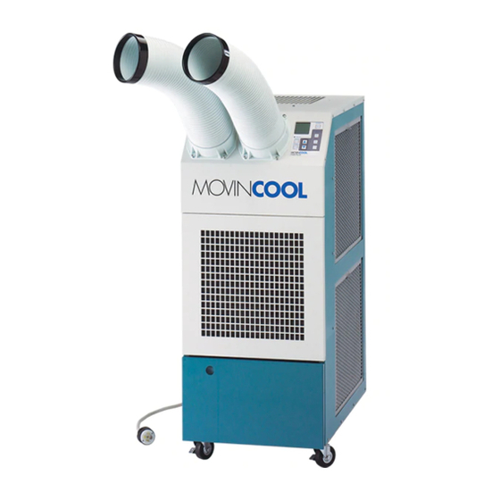
SERVICE
M A N U A L
24HFU and 24HFU-1
DENSO SALES CALIFORNIA, INC.
(800) 264-9573
www.movincool.com
REGISTERED TO ISO 9002
FILE NO. A5537
© 2000 DENSO SALES CALIFORNIA, INC.
All rights reserved. This book may not be reproduced or copied, in whole or in part, without the written permission
of the publisher. DENSO SALES CALIFORNIA, INC. reserves the right to make changes without prior notice.
MovinCool is a registerd trademark of DENSO CORPORATION.
DSCA P/N: LA990009-0205-E
Advertisement

Related Manuals for Movincool 24HFU


Summary of Contents for Movincool 24HFU
- Page 1 All rights reserved. This book may not be reproduced or copied, in whole or in part, without the written permission of the publisher. DENSO SALES CALIFORNIA, INC. reserves the right to make changes without prior notice. MovinCool is a registerd trademark of DENSO CORPORATION. DSCA P/N: LA990009-0205-E...
-
Page 2: Definition Of Terms
FOREWORD This manual has been published to service the MovinCool 24HFU and 24HFU-1. Both the Model 24HFU and 24HFU-1 perform the same basic function, however the 24HFU-1 has additional features. Please use this service manual in servicing Models 24HFU and 24HFU-1. -
Page 3: General Description
(condenser) to exhaust exchanged heat to the out- doors. Unlike conventional air conditioners, the MovinCool Spot Cooling System is a spot cooler which directs cool air to particular areas or objects. MovinCool Spot Cooling Systems have the following features: 1-1. - Page 4 CONSTRUCTION AND SPECIFICATIONS Construction of Models 24HFU & 24HFU-1 MOVINCOOL 24HFU / 24HFU-1 SERVICE PAGE 4...
- Page 5 CONSTRUCTION AND SPECIFICATIONS 2-1. Basic Construction The MovinCool Spot Cooling System is compact in construction because the condenser and the evaporator are enclosed in one unit. The interior is divided into three sections. The upper front face is equipped with the evaporator, while the lower front face contains the drain tank.
- Page 6 45˚C (113˚F), RH ≤50% 45˚C (113˚F), RH ≤50% Intake air temperature range to 25˚C (77˚F), RH ≥50% to 25˚C (77˚F), RH ≥50% [Control Device] Temperature control Without With Specifications Specifications are subject to change without notice. MOVINCOOL 24HFU / 24HFU-1 SERVICE PAGE 6...
-
Page 7: Refrigerant System
• High pressure switch • Capillary tube • Modulating tank These parts are all connected by copper piping. All the connections have been brazed. Condenser Modulating Tank Evaporator Capillary Tube Compressor High Pressure Switch Refrigerant System MOVINCOOL 24HFU / 24HFU-1 SERVICE PAGE 7... - Page 8 2) The open passages are sealed off as gas is drawn into the spiral. 3) As the spiral continues to orbit, the gas is compressed into two increas- ingly smaller pockets. MOVINCOOL 24HFU / 24HFU-1 SERVICE PAGE 8...
- Page 9 Heat is given off and absorbed by air being pulled across the condenser fins by the centrifugal fan and then expelled through the exhaust air duct. MOVINCOOL 24HFU / 24HFU-1 SERVICE PAGE 9...
- Page 10 This generates a signal to open the auxiliary relay. Possible causes of this trouble include: (1) The condenser air filter is dirty, restricting air flow. High Pressure Switch (2) The condenser blower is defective. MOVINCOOL 24HFU / 24HFU-1 SERVICE PAGE 10...
- Page 11 Inlet Pipe Inlet Pipe Compressor Evaporator Discharge Outlet Pipe Pipe Capillary Tube Condenser Outlet Pipe Connecting Pipe (evaporator to compressor) Compressor Suction Connecting Tube Pipe (insulated) (condenser to capillary tube) Refrigerant System Piping MOVINCOOL 24HFU / 24HFU-1 SERVICE PAGE 11...
- Page 12 ELECTRICAL SYSTEM • 24HFU 24HFU Electrical System and Control Box for Model 24HFU MOVINCOOL 24HFU / 24HFU-1 SERVICE PAGE 12...
- Page 13 ELECTRICAL SYSTEM • 24HFU 4-1. Basic Operation of MovinCool Modelp 24HFU Electrical Circuit The three basic modes of operation are as follows: 1) Control Switch in “OFF” position: Operation in “OFF” position a. Current flows through terminals 5 and 2 of the control switch (CS) and to the coil of the auxiliary relay (RX).
- Page 14 • When the auxiliary relay is opened. (Drain switch OFF or high pressure switch OFF.) • When the evaporator has frosted. (Thermostat OFF.) Specifications: Rated Voltage AC 230V Rated Current 30 amps UL Listed File No. E43028 Compressor Relay MOVINCOOL 24HFU / 24HFU-1 SERVICE PAGE 14...
- Page 15 “COOL” mode. The thermostat heat sensing tube is mounted at the evaporator outlet tube and is insulated from surrounding air by heat insulating material. The thermostat contacts are opened at -1.5˚C and closed at +14.5˚C. Thermostat MOVINCOOL 24HFU / 24HFU-1 SERVICE PAGE 15...
- Page 16 FAN or COOL position to start operation. 4-8. Condensate Pump Kit <OPTIONAL> Models 24HFU and 24HFU-1 come standard with a condensate tank, which collects the water that forms on the evaporator during normal cooling operation. If the unit is required to operate continuously without periodic emptying of this tank, a condensate pump may be needed.
- Page 17 ELECTRICAL SYSTEM • 24HFU 4-9. Wiring 24HFU Wiring Diagram for Model 24HFU MOVINCOOL 24HFU / 24HFU-1 SERVICE PAGE 17...
- Page 18 ELECTRICAL SYSTEM • 24HFU-1 24HFU-1 Electrical System and Control Box for Model 24HFU-1 MOVINCOOL 24HFU / 24HFU-1 SERVICE PAGE 18...
- Page 19 ELECTRICAL SYSTEM • 24HFU-1 UNIQUE FEATURES OF MOVINCOOL 24HFU-1 The MovinCool 24HFU-1 is a modified version of Model 24HFU. Model 24HFU-1 has several additional features, which are described below. 4-1. Automatic Restart After Power Interruption A restart auxiliary relay has been added to the electrical system to allow automatic restarting of the system after a power interruption, eliminating the need for manual reset of the control switch.
- Page 20 Because there is a built-in delay circuit to protect the compressor, the compressor will never start up immedi- ately, regardless of the type of operation. This delay is part of the normal operation of Model 24HFU-1 and should not be diagnosed as a malfunction.
- Page 21 E43028 4-6. Condensate Pump Kit <OPTIONAL> Models 24HFU and 24HFU-1 come standard with a condensate tank, which collects the water that forms on the evaporator during normal cooling operation. If the unit is required to operate continuously without periodic emptying of this tank, a condensate pump may be needed. A condensate pump kit is available for Models 24HFU and 24HFU-1.
- Page 22 ELECTRICAL SYSTEM • 24HFU-1 4-7. Wiring 24HFU-1 Wiring Diagram for Model 24HFU-1 MOVINCOOL 24HFU / 24HFU-1 SERVICE PAGE 22...
- Page 23 DATA 24HFU Exterior Dimensions of Models 24HFU & 24HFU-1 MOVINCOOL 24HFU / 24HFU-1 SERVICE PAGE 23...
- Page 24 Evaporator Service Panel Drain Pan Air Filter Drain Tube Compressor (Evaporator) Conduit Control Box Drain Switch Rear Panel Castor Drain Tank Castor Base Panel Power Cord Construction Diagram of Models 24HFU & 24HFU-1 MOVINCOOL 24HFU / 24HFU-1 SERVICE PAGE 24...
- Page 25 DATA Models 24HFU & 24HFU-1 5-1. Cooling Capability Characteristics 1) Cooling capability curve Cooling Capability Curve 2) Power consumption curve Models 24HFU & 24HFU-1 Power Consumption Curve MOVINCOOL 24HFU / 24HFU-1 SERVICE PAGE 25...
- Page 26 DATA Models 24HFU & 24HFU-1 3) Cool air temperature difference curve Cool Air Temperature Difference Curve MOVINCOOL 24HFU / 24HFU-1 SERVICE PAGE 26...
-
Page 27: Repair - Troubleshooting
1-1. Inspection of Power Source Voltage Check the voltage of the power source. 24HFU & 24HFU-1: Single phase 230 volts (60Hz) Check the operation and condition of the fuse or circuit breaker in the power source. 1-2. Inspection of Air Filters Remove the air filters and check the element. - Page 28 If the difference is out of the range given in the graphs on page 27 and 28 proceed with the remedy suggested in the troubleshooting chart on page 31. Inspection of Cooling Capacity MOVINCOOL 24HFU / 24HFU-1 SERVICE PAGE 28...
- Page 29 14. Drain pan Blower housing (condenser) 15. Left side panel Condenser fan 16. Drain tank Rear panel 17. Service panel Drain switch 18. Thermostat Caster 10. Full tank lamp Disassembly of Models 24HFU & 24HFU-1 MOVINCOOL 24HFU / 24HFU-1 SERVICE PAGE 29...
- Page 30 Removal of Panels B) Disconnect the three lead wires of the power cord from the control box. Loosen the two screws securing the wire clamp and then remove the power cord. Removal of Power Cord MOVINCOOL 24HFU / 24HFU-1 SERVICE PAGE 30...
- Page 31 REPAIR - DISASSEMBLY 3-2. Removal of Electrical Parts 3-2-1. For Model 24HFU disconnect the electrical wiring from the components indicated in the diagram below. 24HFU Wiring Diagram for Model 24HFU MOVINCOOL 24HFU / 24HFU-1 SERVICE PAGE 31...
- Page 32 REPAIR - DISASSEMBLY 3-2-1. Continued For Model 24HFU-1 disconnect the electrical wiring from the components indicated in the diagram below. 24HFU-1 Wiring Diagram for Model 24HFU-1 MOVINCOOL 24HFU / 24HFU-1 SERVICE PAGE 32...
- Page 33 Remove the electrical parts in the control box. 24HFU 24HFU-1 Removal of Electrical Parts in the Control Box 3-2-3. Remove the control switch and full tank lamp as shown in figure. Removal of Control Switch MOVINCOOL 24HFU / 24HFU-1 SERVICE PAGE 33...
- Page 34 3-3. Removal of Blower Assembly 1. Condenser fan 5. Partition plate 2. Blower housing (condenser) 6. Evaporator fan 3. Fan motor 7. Blower housing (evaporator) 4. Motor bracket 8. Air flow guide Disassembly of Blower MOVINCOOL 24HFU / 24HFU-1 SERVICE PAGE 34...
- Page 35 A - NUT B - SCREW Removal of Nut 3-3-4. Remove the centrifugal fan by loosening the set bolt on the shaft. Remove the blower motor, by loosening “A” nuts. Removal of Fan MOVINCOOL 24HFU / 24HFU-1 SERVICE PAGE 35...
- Page 36 REPAIR - INSPECTION AND REPAIR OF ELECTRICAL SYSTEM • 24HFU 24HFU 4-1. Inspection of Auxiliary Relay Check for continuity across the terminals when the test button is depressed and when it is released. Terminals State of Reset Switch Continuity 11-12...
- Page 37 REPAIR - INSPECTION AND REPAIR OF ELECTRICAL SYSTEM • 24HFU 4-4. Inspection of Full Tank Warning Lamp Make a test circuit as shown. If the lamp fails to light up, replace it. Inspection of Full Tank Warning Lamp 4-5. Inspection of Drain Switch Check for continuity between terminals 1 and 2.
- Page 38 REPAIR - INSPECTION AND REPAIR OF ELECTRICAL SYSTEM • 24HFU 4-8. Inspection of Wiring Connection Refer to the Wiring Diagrams 3-2-1. (pg. 35 and 36) and check for connection of each wire. 4-9. Inspection of Anti-freezing Thermostat Check for continuity across two terminals of the thermostat.
- Page 39 REPAIR - INSPECTION AND REPAIR OF ELECTRICAL SYSTEM • 24HFU-1 24HFU-1 UNIQUE FEATURES OF MODEL 24HFU-1 4-1. Inspection of Time Delay Relay Check for continuity between terminals 1 and 9, and 4 and 12. Continuity should exist. With rated voltage applied at terminal 13 and 14 (and after a time delay of 75 seconds) continuity should exist between terminals 5 and 9, and 8 and 12.
- Page 40 REPAIR - INSPECTION AND REPAIR OF ELECTRICAL SYSTEM • 24HFU-1 4-3. Inspection of Room Thermostat Check for continuity between terminals 2 and 3, at room temperature (16˚C/61˚F or higher). Continuity should exist. If continuity does not exist, replace the room thermostat.
- Page 41 All these factors will reduce effectiveness of brazing. It is necessary to eliminate excess brazing filler metal using sand paper and by cleaning thoroughly with a solvent such as Trichlene. MOVINCOOL 24HFU / 24HFU-1 SERVICE PAGE 41...
- Page 42 1. Evaporator 2. Capillary tube 3. Condenser 4. Compressor NOTE Hold the compressor body, not the tube, when carrying the compressor. Removal of Refrigerant Cycle Components MOVINCOOL 24HFU / 24HFU-1 SERVICE PAGE 42...
- Page 43 REPAIR - INSPECTION AND REPAIR OF REFRIGERANT SYSTEM 24HFU Removal of Refrigerant Cycle Components (Refer to 5-2-2.) PART REPLACED DISCONNECT AT: Compressor A & B Condenser A & C Capillary tube D & E Evaporator E & F Refrigerant Cycle MOVINCOOL 24HFU / 24HFU-1 SERVICE PAGE 43...
- Page 44 (2) Fit the process tube fitting to the pinch-off tube on both sides. Mounting of Process Tube Fitting MOVINCOOL 24HFU / 24HFU-1 SERVICE PAGE 44...
- Page 45 Checking Vacuum vacuum. 5-3-4. Checking Gas Leak (1) Remove the charging hose (green) from the vacuum pump, and connect the hose to the refrigerant cylinder (R22). Evacuating Air Inside Charging Hose MOVINCOOL 24HFU / 24HFU-1 SERVICE PAGE 45...
- Page 46 (2) Loosen the nut on the gauge manifold side of the charging hose (green). Open the valve of the charging hose (green). Open the valve of the refrigerant cylinder. Evacuating Air Inside Charging Hose MOVINCOOL 24HFU / 24HFU-1 SERVICE PAGE 46...
- Page 47 (3) Braze the end of the pinch-off tube. (4) Ensure that a gas leak is not present at the pinched off portion and the brazed end. Removal of Gauge Manifold MOVINCOOL 24HFU / 24HFU-1 SERVICE PAGE 47...
- Page 48 Secure the wires using clamps in the same position they were before removal. 6-4. Perform the inspection of cooling capacity and check for abnormal noise or abnormal vibration. MOVINCOOL 24HFU / 24HFU-1 SERVICE PAGE 48...
Need help?
Do you have a question about the 24HFU and is the answer not in the manual?
Questions and answers