
Related Manuals for rtd FPGA35S6045HR


Summary of Contents for rtd FPGA35S6045HR
- Page 1 FPGA35S6045HR FPGA35S6100HR FPGA Module User’s Manual BDM-610010045 Rev. C RTD Embedded Technologies, Inc. AS9100 and ISO 9001 Certified...
- Page 2 RTD Embedded Technologies, Inc. 103 Innovation Boulevard State College, PA 16803 USA Telephone: 814-234-8087 Fax: 814-234-5218 www.rtd.com sales@rtd.com techsupport@rtd.com...
-
Page 3: Revision History
Failure to follow the instructions found in this manual may result in damage to the product described in this manual, or other components of the system. The procedure set forth in this manual shall only be performed by persons qualified to service electronic equipment. Contents and specifications within this manual are given without warranty, and are subject to change without notice. RTD Embedded Technologies, Inc. shall not be liable for errors or omissions in this manual, or for any loss, damage, or injury in connection with the use of this manual. -
Page 4: Table Of Contents
B1: Pull up Voltage B2: Pull up Voltage Steps for Installing ..................................22 Functional Description Oscillator ....................................23 EEPROM ....................................23 DDR2 SRAM ..................................... 23 Digital I/O ....................................24 Register Address Space | www.rtd.com FPGA35S6 User’s Manual RTD Embedded Technologies, Inc. - Page 5 6.1.15 R_PORT2H_DIR (Read/Write) 6.1.16 R_DDR_RD_DATA (Read) 6.1.17 R_DDR_WR_DATA (Read/Write) 6.1.18 R_DDR_ADDR (Read/Write) 6.1.19 R_DDR_STATUS (Read) Troubleshooting Additional Information PC/104 Specifications ................................29 PCI and PCI Express Specification ............................29 Limited Warranty | www.rtd.com FPGA35S6 User’s Manual RTD Embedded Technologies, Inc.
- Page 6 Table 13: Pull up/Pull down Jumper options ................................21 Table 14: B1 Pull up Voltage ....................................21 Table 15: B2 Pull up Voltage ....................................21 Table 16: FPGA Example Register Map................................. 25 | www.rtd.com FPGA35S6 User’s Manual RTD Embedded Technologies, Inc.
-
Page 7: Introduction
PCI Express Bus: PCIe/104 Universal Board Interfaces with Type 1 or Type 2 bus No re-population Provides 2.5 Gbps in each direction In-band interrupts and messages Message Signaled Interrupt (MSI) support | www.rtd.com FPGA35S6 User’s Manual RTD Embedded Technologies, Inc. -
Page 8: Ordering Information
If you are having problems with you system, please try the steps in the Troubleshooting section of this manual. For help with this product, or any other product made by RTD, you can contact RTD Embedded Technologies technical support via the... -
Page 9: Specifications
Access Rate Mb/s (1): Typical power consumption based on RTD’s FPGA example. Note: (2): Proving by design, not production tested. For additionally electrical characteristic of the Spartan 6 I/O refer to http://www.xilinx.com | www.rtd.com FPGA35S6 User’s Manual RTD Embedded Technologies, Inc. -
Page 10: Board Connection
Physical Characteristics Weight: Approximately 63.5 g (0.14 lbs.) Dimensions: 90.17 mm L x 95.89 mm W (3.550 in L x 3.775 in W) Figure 1: Board Dimensions | www.rtd.com FPGA35S6 User’s Manual RTD Embedded Technologies, Inc. -
Page 11: Connectors And Jumpers
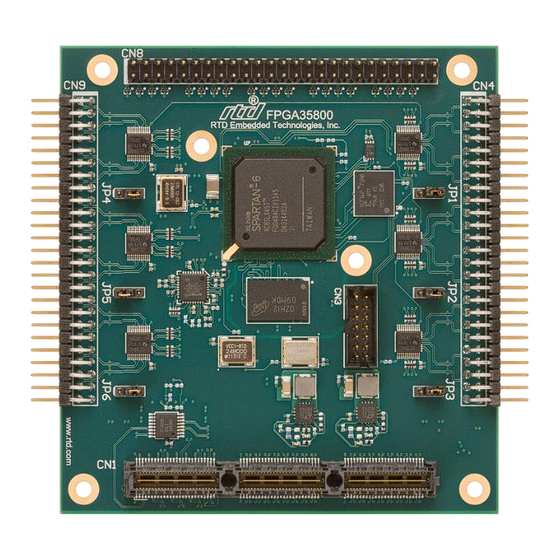
CN4: Digital I/O JP4, JP5 & JP6: Pull up/Pull down JP1, JP2 & JP3: Jumper Pull up/Pull down Jumper CN3: Programming Header CN1 & CN2: PCIe Connector Figure 2: Board Connections | www.rtd.com FPGA35S6 User’s Manual RTD Embedded Technologies, Inc. -
Page 12: External I/O Connectors
Connector CN3 provides a connection to the Xilinx JTAG programming header. The pin assignment for CN3 is shown below. This connector header mates with the Xilinx OEM programming cable. Table 4: CN3 Programming Header 3.3V VRef | www.rtd.com FPGA35S6 User’s Manual RTD Embedded Technologies, Inc. -
Page 13: Cn8: High Speed Digital I/O Connector
Port2_p[4] Port2_n[5] Port2_p[5] Port2_n[6] Port2_p[6] Port2_n[7] Port2_p[7] Port2_n[8] Port2_p[8] Port2_n[9] Port2_p[9] Port2_n[10] Port2_p[10] Port2_n[11] Port2_p[11] Port2_n[12] Port2_p[12] Port2_n[13] Port2_p[13] Port2_n[14] Port2_p[14] Port2_n[15] Port2_p[15] Port2_n[16] Port2_p[16] Port2_n[17] Port2_p[17] Port2_n[18] Port2_p[18] Port2_n[19] Port2_p[19] | www.rtd.com FPGA35S6 User’s Manual RTD Embedded Technologies, Inc. -
Page 14: Cn4 & Cn9: Digital I/O Connector
Table 8: Pull up/Pull down Jumper options Setting Description I/O is pulled up to 3.3V or 5V (Set by B1 and B2) I/O is pulled down to GND No Jumper I/O has no pull up/pull down | www.rtd.com FPGA35S6 User’s Manual RTD Embedded Technologies, Inc. -
Page 15: Jp7: Reserved
Solder jumper B1 are used to set the pull up voltage for JP4, JP5 and JP6. Table 10: B2 Pull up Voltage Setting Description Sets Pull up voltage to 3.3V Sets Pull up voltage to 5V | www.rtd.com FPGA35S6 User’s Manual RTD Embedded Technologies, Inc. -
Page 16: Steps For Installing
10. Attach any necessary cables to the PC/104 stack. 11. Re-connect the power cord and apply power to the stack. 12. Boot the system and verify that all of the hardware is working properly. Figure 4: Example 104™Stack | www.rtd.com FPGA35S6 User’s Manual RTD Embedded Technologies, Inc. -
Page 17: Idan Connections
Weight: Approximately 0.42 Kg (0.92 lbs.) Dimensions: 152mm L x 130mm W x 34mm H (5.983" L x 5.117" W x 1.339" H) 1.339” [34mm] Front 5.983” [152mm] 5.117” [130mm] Back Figure 5: IDAN Dimensions | www.rtd.com FPGA35S6 User’s Manual RTD Embedded Technologies, Inc. -
Page 18: Connectors And Jumpers
| www.rtd.com FPGA35S6 User’s Manual RTD Embedded Technologies, Inc. -
Page 19: P4: High Speed Digital I/O Connector
IDAN P4 Pin Row 1 Row 2 Row 3 Signal C8 Pin Port2_p[0] Port2_n[0] Port2_p[1] Port2_n[1] Port2_p[2] Port2_n[2] Port2_p[3] Port2_n[3] Port2_p[4] Port2_n[4] Port2_p[5] Port2_n[5] Port2_p[6] Port2_n[6] Port2_p[7] Port2_n[7] Port2_p[8] Port2_n[8] Port2_p[9] Port2_n[9] | www.rtd.com FPGA35S6 User’s Manual RTD Embedded Technologies, Inc. - Page 20 Port2_n[10] Port2_p[11] Port2_n[11] Port2_p[12] Port2_n[12] Port2_p[13] Port2_n[13] Port2_p[14] Port2_n[14] Port2_p[15] Port2_n[15] Port2_p[16] Port2_n[16] Port2_p[17] Port2_n[17] Port2_p[18] Port2_n[18] Port2_p[19] Port2_n[19] Reserved Reserved Reserved Reserved Reserved Reserved Reserved Reserved Reserved Reserved Reserved Reserved | www.rtd.com FPGA35S6 User’s Manual RTD Embedded Technologies, Inc.
-
Page 21: Bus Connectors
Solder jumper B1 are used to set the pull up voltage for JP4, JP5 and JP6. Table 15: B2 Pull up Voltage Setting Description Sets Pull up voltage to 3.3V Sets Pull up voltage to 5V | www.rtd.com FPGA35S6 User’s Manual RTD Embedded Technologies, Inc. -
Page 22: Steps For Installing
10. Attach any necessary cables to the IDAN system. 11. Re-connect the power cord and apply power to the stack. 12. Boot the system and verify that all of the hardware is working properly. Figure 6: Example IDAN System | www.rtd.com FPGA35S6 User’s Manual RTD Embedded Technologies, Inc. -
Page 23: Functional Description
The FPGA35S6 features a 1Gb DDR2 SRAM, MT47H64M16HR 25E. This is interface to the Spartan 6 FPGA using Xilinx Memory Interface Generators (MIG) core. The example FPGA code has demonstrated how to use this core in a FPGA design. | www.rtd.com FPGA35S6 User’s Manual RTD Embedded Technologies, Inc. -
Page 24: Digital I/O
The FPGA35S6 digital I/O on connectors CN4 and CN9 use the circuitry shown below to level shift the input voltage from 5V to 3.3V allowing the I/O on these connectors to be 5V tolerant. CN4/CN9 33Ω Xilinx Level Shifter Spartan 6 10KΩ +5V/3.3V Figure 8: CN4/CN9 Digital I/O Circuitry | www.rtd.com FPGA35S6 User’s Manual RTD Embedded Technologies, Inc. -
Page 25: Register Address Space
B4: 1.2V pgood B5: 1.8V pgood B6: 3.3V pgood 6.1.3 R_EEPROM (R RITE This register has the outputs to the EEPROM. B0: EEPROM Serial Clock B1: EEPROM Serial Input B2: EEPROM Chip Select | www.rtd.com FPGA35S6 User’s Manual RTD Embedded Technologies, Inc. -
Page 26: R_Port0_In (Read)
A read is performed by writing address to R_DDR_ADDR. 6.1.17 R_DDR_WR_DATA (R RITE Writes data in registry to location R_DDR_ADDR of the DDR2 SRAM 6.1.18 R_DDR_ADDR (R RITE Address pointer of the DDR2 SRAM. | www.rtd.com FPGA35S6 User’s Manual RTD Embedded Technologies, Inc. -
Page 27: R_Ddr_Status (Read)
B2: Read empty B3: Read full B4: Write error B5: Write underrun B6: Write empty B7: Write full B[14:8]: Read count B[22:16]: Write count B[24]: Command full B[25]: Command empty B[31]: Calibration done | www.rtd.com FPGA35S6 User’s Manual RTD Embedded Technologies, Inc. -
Page 28: Troubleshooting
Swap Components – Try replacing parts in the system one at a time with similar parts to determine if a part is faulty or if a type of part is configured incorrectly. If problems persist, or you have questions about configuring this product, contact RTD Embedded Technologies via the following methods: Phone:... -
Page 29: Additional Information
A copy of the latest PC/104 specifications can be found on the webpage for the PC/104 Embedded Consortium: www.pc104.org PCI and PCI Express Specification A copy of the latest PCI and PCI Express specifications can be found on the webpage for the PCI Special Interest Group: www.pcisig.com | www.rtd.com FPGA35S6 User’s Manual RTD Embedded Technologies, Inc. -
Page 30: Limited Warranty
During the one year warranty period, RTD Embedded Technologies will repair or replace, at its option, any defective products or parts at no additional charge, provided that the product is returned, shipping prepaid, to RTD Embedded Technologies. All replaced parts and products become the property of RTD Embedded Technologies. - Page 31 RTD Embedded Technologies, Inc. 103 Innovation Boulevard State College, PA 16803 USA Telephone: 814-234-8087 Fax: 814-234-5218 www.rtd.com sales@rtd.com techsupport@rtd.com Copyright 2014 by RTD Embedded Technologies, Inc. All rights reserved.
Need help?
Do you have a question about the FPGA35S6045HR and is the answer not in the manual?
Questions and answers