
Related Manuals for rtd BDM-610000049


Summary of Contents for rtd BDM-610000049
-
Page 1: Cmx158886 Cpumodules
CMX158886 cpuModules™ User’s Manual BDM-610000049 Revision G ® www.rtd.com An ISO9001:2000 Company “Accessing the Analog World” ®... - Page 2 RTD, and the RTD logo are registered trademarks of RTD Embedded Technologies, Inc. PS/2, PC/XT, PC/AT, and IBM are trademarks of International Business Machines Inc. MS-DOS, Windows, Windows 95, Windows 98, and Windows NT are trademarks of Microsoft Corporation. Linux is a registered trademark of Linus Torvalds.
- Page 3 CMX158886 cpuModules™ ® www.rtd.com An ISO9001:2000 Company “Accessing the Analog World” ®...
- Page 4 CMX158886 cpuModule BDM-610000049 Rev G...
-
Page 5: Table Of Contents
System Reset....................BDM-610000049 Rev G... - Page 6 Booting to Boot Block Flash with Fail Safe Boot ROM ............vi CMX158886 cpuModule BDM-610000049 Rev G...
- Page 7 DVMT Mode Select ..................BDM-610000049 Rev G...
- Page 8 Serial Port Programming ................107 viii CMX158886 cpuModule BDM-610000049 Rev G...
- Page 9 PC/104 and PC/104-Plus Specifications ............. . . 107 Appendix E Limited Warranty BDM-610000049 Rev G...
- Page 10 CMX158886 cpuModule BDM-610000049 Rev G...
-
Page 11: Chapter 1 Introduction
RTD Intelligent Data Acquisition Node (IDAN) frame Appendix D Additional Information lists sources and websites to support the cpuModule installation and configuration Appendix E Limited Warranty BDM-610000049 Rev G Chapter 1: Introduction 1... -
Page 12: Cmx158886 Cpumodules
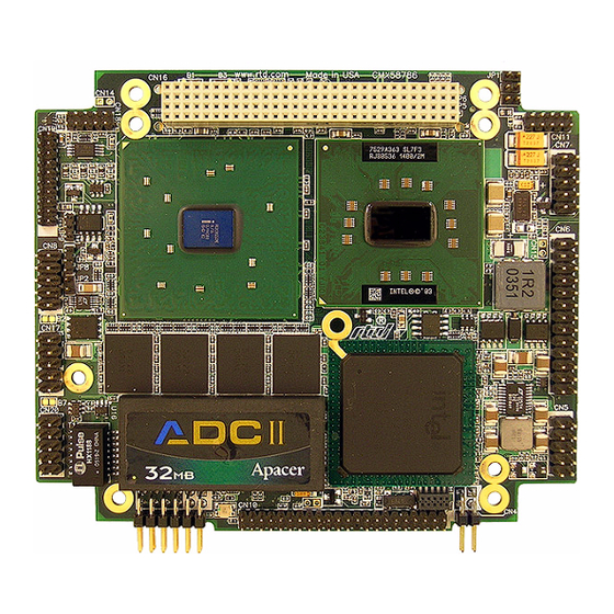
Auxiliary Power (U16) 2 CMX158886 cpuModule Power Mngmt. PCI Bus (CN16) (CN12) Battery (CN13) (CN3) EIDE (CN10) Figure 1 CMX158886 cpuModule (top view) Audio (CN11) COM1 (CN7) Switched (CN15) multiPort (CN6) Multi- Function (CN5) ISA Bridge Link (CN4) BDM-610000049 Rev G... -
Page 13: Enhanced Intel Speedstep (Px Only)
Interrupts are generated when the 8 bit-direction programmable digital inputs match a pattern or on any value change event. Bit masking BDM-610000049 Rev G Chapter 1: Introduction 3... - Page 14 The strobe input latches data into the bit-programmable port and generates an interrupt. Any of the interrupt modes can be used to generate a wake event from any standby/powerdown mode. 4 CMX158886 cpuModule BDM-610000049 Rev G...
-
Page 15: Ordering Information
CMX158886PX1400HR-512 CMX158886PX1400HR-E512 CMX158886PX1400HR-1024 CMX158886CX1000HR-512 CMX158886CX1000HR-E512 CMX158886CX1000HR-1024 BDM-610000049 Rev G Table 1 CMX158886 cpuModule Model Options Description 1.4 GHz Pentium-M, 512MB DDR-SDRAM cpuModule 1.4 GHz Pentium-M, 512MB DDR-SDRAM cpuModule with ECC 1.4 GHz Pentium-M, 1024MB DDR-SDRAM cpuModule 1.0 GHz Celeron-M, 512MB DDR-SDRAM cpuModule 1.0 GHz Celeron-M, 512MB DDR-SDRAM cpuModule with ECC... -
Page 16: Cable Kits And Accessories
A floppy drive cable kit (P/N XK-CM49) is also available for connecting to the multiPort. This cable kit comes with: • 3.5” HDD Floppy Drive with a multiPort interface board • Two floppy cables For additional accessories, refer to the RTD website. 6 CMX158886 cpuModule BDM-610000049 Rev G... -
Page 17: Board Features
CPU Clock Throttling and Clock Stop for C0 to C3 Support – Wake events include: • aDIO Interrupt • Wake-on-LAN • Real Time Clock • COM port Ring • Power Switch • etc. • Network Boot supported by Intel PXE BDM-610000049 Rev G Chapter 1: Introduction 7... -
Page 18: I/O
Each serial port connector can be configured as two limited serial ports, for a total of four serial ports • multiPort function connector – Parallel port • SPP, PS/2 bi-directional, EPP & ECP – Advanced Digital I/O (aDIO) 8 CMX158886 cpuModule BDM-610000049 Rev G... -
Page 19: Bios
Nonvolatile storage of CMOS settings without battery • Boot Devices – Standard Devices (floppy disk, hard disk, etc.) – ATA/IDE Disk Chip During the time of this manual’s publication, 4GB was the largest available ATA/IDE Disk Chip capacity BDM-610000049 Rev G Chapter 1: Introduction 9... - Page 20 – USB Device – Network – Fail Safe Boot ROM • Surface-mount Flash chip that holds ROM-DOS™ • Quick Boot mode 10 CMX158886 cpuModule BDM-610000049 Rev G...
-
Page 21: Block Diagram
The cpuModule and BIOS are also compatible with most real-time operating systems for PC compatible computers, although these may require creation of custom drivers to use the aDIO and watchdog timer. BDM-610000049 Rev G 8 5 5 G M E... -
Page 22: Specifications
Standard Temperature Storage Temperature Humidity Non-Condensing Mean Time Before 23 C Failure Power, typ. Power, Max. 12.7 W 15.2 W 10.9 W 12.2 W Min. Max. 4.75V 5.25V 4.75V 5.25V 500mA -40C +85C -40C +85C 110,000 hours BDM-610000049 Rev G... - Page 23 Symbol 3.3V BKLT BDM-610000049 Rev G Table 4 Electrical Characteristics Parameter Test Condition Output Voltage High = –0.5 mA Output Voltage Low = 6.0 mA Input Voltage High — Input Voltage Low — 3.3V supplied to PCI — bus from power...
- Page 24 0.3 V -25 V 25 V 2.4 V 3.3 V 0.0 V 0.4 V 2.0 V 5.5 V -0.5 V 0.8 V 500 mA 2.0V 3.6 V 500 mA 2.0 V 5.5 V -0.5 V 0.8 V BDM-610000049 Rev G...
-
Page 25: Contact Information
3. Only required to maintain date and time when power is completely removed from the system. Not required for board operation. Contact Information RTD Embedded Technologies, Inc. 103 Innovation Blvd. State College, PA 16803-0906 Phone: +1-814-234-8087 Fax: +1-814-234-5218 E-mail: sales@rtd.com techsupport@rtd.com Internet: http://www.rtd.com BDM-610000049 Rev G Chapter 1: Introduction 15... - Page 26 16 CMX158886 cpuModule BDM-610000049 Rev G...
-
Page 27: Chapter 2 Getting Started
Connect a keyboard. Default BIOS configuration. Fail Safe Boot ROM. Connect a VGA monitor to the SVGA connector. Refer to the remainder of this chapter for details on each of these steps. BDM-610000049 Rev G Chapter 2: Getting Started 17... -
Page 28: Connector Locations
PC104-Plus or PCI-104 modules. 18 CMX158886 cpuModule Power Mngmt. PCI Bus (CN16) (CN12) Battery (CN13) (CN3) EIDE (CN10) Figure 3 CMX158886 Connector Locations Audio (CN11) COM1 (CN7) Switched (CN15) multiPort (CN6) Multi- Function (CN5) ISA Bridge Link (CN4) BDM-610000049 Rev G... - Page 29 Some PCI-104 and PC/104-Plus expansion cards may require +3.3V supplied on the PC/104-Plus (PCI) connector (CN16). To learn how to supply this voltage, refer to Auxiliary Power (CN3) on page 26 and Jumper Settings and Locations on page 86. BDM-610000049 Rev G Table 5 CMX158886 Basic Connectors Function...
-
Page 30: Connecting The Utility Cable
Note Many keyboards are switchable between PC/XT and AT operating modes, with the mode usually selected by a switch on the back or bottom of the keyboard. For correct operation with this cpuModule, you must select AT mode. Connecting to the PC/104-Plus (PCI) Bus Other PC/104-Plus or PCI-104 expansion boards may be connected to the cpuModule’s PC/104-Plus (PCI) bus... -
Page 31: Slot Selection Switches
4 PCI cards that can be stacked onto the cpuModule with switch positions 0 through 3. The distance from the CPU determines these switch settings. The card closest to the CPU is said to be in slot 0, the next closest slot 1 and so on to the final card as slot 3. -
Page 32: Booting The Cmx158886 Cpumodule For The First Time
Note You may miss the initial sign-on messages if your monitor takes a while to power on. Note By default, cpuModules are shipped with Fail Safe Boot ROM enabled. When Fail Safe Boot ROM is enabled, the system will boot to it exclusively. 22 CMX158886 cpuModule BDM-610000049 Rev G... -
Page 33: Chapter 3 Connecting The Cpumodule
PC/104-Plus PCI Bus (CN16)—page 49 Bridge Link (CN4)—page 52 External Power Management (CN12)—page 53 Optional RTC Battery Input (CN13)—page 53 Fan Power, +5 V (CN14)—page 53 Fan Power, Switched (CN15)—page 54 BDM-610000049 Rev G Chapter 3: Connecting the cpuModule 23... -
Page 34: Proper Grounding Techniques
PC104-Plus or PCI-104 modules. 24 CMX158886 cpuModule Power Mngmt. PCI Bus (CN16) (CN12) Battery (CN13) (CN3) EIDE (CN10) Figure 4 CMX158886 Connector Locations Audio (CN11) COM1 (CN7) Switched (CN15) multiPort (CN6) Multi- Function (CN5) ISA Bridge Link (CN4) BDM-610000049 Rev G... - Page 35 CN10 CN11 CN12 CN13 CN14 CN15 CN16 CN17 CN18 CN19 CN20 BDM-610000049 Rev G Table 6 CMX158886 Basic Connectors Function Auxiliary Power Bridge Link Utility Port multiPort Serial Port 1 (COM1) Serial Port 2 (COM2) EIDE Connector Audio Connector External Power Management...
-
Page 36: Auxiliary Power (Cn3)
See note below PSON# Power Supply On (ATX) +3.3 V See note below 1. For more information on the ATX style signals, +5V Standby and PSON#, refer to the Power Management section in Chapter 4, Using the cpuModule. BDM-610000049 Rev G... - Page 37 PCI bus connector (CN16), or the LVDS FLat Panel Video connector (CN19), contact RTD Technical Support. Facing the connector pins, the pinout of the Auxiliary Power connector is: PSON# +3.3 V BDM-610000049 Rev G Reserved +3.3 V +5 V –12 V...
-
Page 38: Utility Port Connector (Cn5)
Table 8 Utility Port Connector (CN5) Signal Function SPKR+ Speaker Output (open collector) +5 V RESET Manual Push-Button Reset PWRSW Soft Power Button Keyboard Data Keyboard Clock Ground Mouse Clock RTC Battery Input Mouse Data PWRSW In/Out in/out — in/out RESET SPKR+ BDM-610000049 Rev G... -
Page 39: Keyboard
PS/2 keyboard connector. To ensure correct operation, check that the keyboard is either an AT compatible keyboard or a switchable XT/AT keyboard set to AT mode. Switchable keyboards are usually set by a switch on the back or bottom of the keyboard. -
Page 40: Battery
Connecting a battery is only required to maintain time when power is completely removed from the cpuModule. A battery is not required for board operation. WARNING The optional RTC battery input connector (CN13) should be left unconnected if the multi-function connector (CN5) has a battery connected to pin 9. 30 CMX158886 cpuModule BDM-610000049 Rev G... -
Page 41: Svga Video Connector (Cn18)
SVGA Video Connector (CN18) Table 11 provides the pinout of the video connector. Facing the connector pins of the SVGA Video connector (CN18), the pinout is: BDM-610000049 Rev G Table 11 SVGA Video Connector (CN18) Signal Function VSYNC Vertical Sync... - Page 42 60, 65, 70, 72, 75, 85, 100, 120 Hz 256, 64k, 16M 60, 75 Hz 256, 64k, 16M 50, 60, 75, 85, 100 Hz 256, 64k, 16M 60, 75 Hz 256, 64k, 16M 60, 75, 85 Hz 256, 64k, 16M 60, 75 Hz BDM-610000049 Rev G...
-
Page 43: Lvds Flat Panel Video Connector (Cn19)
Table 14 lists several LVDS panels that were tested with this cpuModule. When evaluating a panel to be used with this cpuModule, review the specifications of the tested panels to assure compatability. Manufacturer Optrex Optrex BDM-610000049 Rev G Table 13 Flat Panel Video Connector (CN19) Signal Function LVDS Data 0+... -
Page 44: Eide Connector (Cn10)
DIOR#:HDMARDY#:HSTROBE IORDY:DDMARDY#:DSTROB DMACK# INTRQ CS0# DASP# +5 V (logic) 1. Signals marked with (#) are active low. 34 CMX158886 cpuModule Table 15 EIDE Connector (CN10) Signal DD10 DD11 DD12 DD13 DD14 DD15 PDIAG CS1# +5 V (motor) BDM-610000049 Rev G... -
Page 45: Ata/Ide Disk Chip Socket (U16)
Specify the IDE mode of the ATA/IDE Disk Chip. For more information on the supported IDE modes, refer to Configuring the ATA/IDE Disk Chip Socket section of this manual on page 68. BDM-610000049 Rev G Table 16 ATA/IDE Disk Chip Socket (U16) - Page 46 Re-enter the BIOS and set the boot order of the system accordingly. ATA/IDE Disk Chip Socket (U16) Pin 1 indicated by arrow Figure 5 CMX158886 before and after ATA/IDE Disk Chip Installation 36 CMX158886 cpuModule ATA/IDE Disk Chip Pin 1 indicated by arrow BDM-610000049 Rev G...
-
Page 47: Serial Port 1 (Cn7) And Serial Port 2 (Cn8)
RS-232 compatible devices. Table 18 provides the serial port connector pinout and shows how to connect to an external DB-25 or DB-9 compatible serial connector. 9,10 BDM-610000049 Rev G Table 17 Serial Port Settings I/O Address (hex) 03F8... -
Page 48: Rs-422 Or Rs-485 Serial Port
TXD+ TXD+ RXD+ RXD– TXD– TXD– RXD– Table 20 Half-Duplex RS-485 Mode From Port 1 TXD+ Port 1 RXD+ Port 1 TXD– Port 1 RXD– Port 1 TXD+ Port 2 RXD+ Port 1 RXD– Port 2 TXD– BDM-610000049 Rev G... -
Page 49: Rs-422 And Rs-485 Mode Pinout
If MCR bit 1 = 0, then RTS* = 1, and serial transmitters are enabled Note For more information on the serial port registers, including the MCR, refer to the Serial Port Programming reference in Appendix D. BDM-610000049 Rev G Table 21 Serial Port in RS-422/485 Mode Signal Function —... -
Page 50: Dual Serial Port Modes
TXD2 COM B - Transmit Data COM A - Ring Indicate Signal Ground COM B COM 3 COM 4 JP12/JP14 Not Installed Not Installed CN7: JP12 CN8: JP14 Not Installed CN7: JP12 CN8: JP14 In/Out DB-9 — BDM-610000049 Rev G... - Page 51 Table 25 COM A (RS-422/485) and COM B (RS-232) 9,10 Table 26 COM A (RS-422/485) and COM B (RS-422/485) 9,10 BDM-610000049 Rev G Signal Function DCD1 COM A - Data Carrier Detect RXD2 COM B - Receive Data RXD1- COM A - Receive Data (–)
-
Page 52: Multiport™ (Cn6)
62 for information on programming the multiPort. 42 CMX158886 cpuModule Table 27 multiPort aDIO Pinout CN6 Pin Function CN6 Pin strobe 0 P1-0 P1-1 P1-2 P1-3 P1-4 P1-5 P1-6 P1-7 P0-0 P0-1 P0-2 P0-3 Function P0-4 P0-5 P0-6 P0-7 strobe 1 +5 V BDM-610000049 Rev G... -
Page 53: Multiport Configured As A Parallel Port
Table 28 lists the parallel port signals and explains how to connect it to a DB-25 connector to obtain a PC compatible port. Table 28 multiPort Connector (CN6) as a Parallel Port CN6 Pin BDM-610000049 Rev G Signal Function In/Out... -
Page 54: Multiport Configured As A Floppy Drive Controller
TRK0# DIR# WRTPRT# STEP# RDATA# DSKCHG — MTR0# — DS1# MTR1# WDATA# WGATE# +5 V — Floppy Drive Pin — odd pins — odd pins odd pins — odd pins odd pins odd pins odd pins — BDM-610000049 Rev G... -
Page 55: Usb 2.0 Connector (Cn17)
Two USB 2.0 compliant connectors are available on connector CN17. Table 30 provides the pinout of the USB connector. Note For proper operation at USB 2.0 speeds, be sure to use a cable that is rated for USB 2.0, such as the cable kit supplied by RTD. BDM-610000049 Rev G Table 30 USB Connector (CN17) Signal Function... - Page 56 Facing the connector pins, the pinout of CN17 is: 46 CMX158886 cpuModule DATA1+ DATA1– DATA2+ DATA2– VCC1 VCC2 BDM-610000049 Rev G...
-
Page 57: Ethernet (10/100Base-T And -Tx) Connector (Cn20)
The functionality of the Ethernet port is based on the Intel 82562 Fast Ethernet PCI controller. Table 31 provides the pinout of the Ethernet connector. RJ-45 Pin 10-Pin DIL Pin — — AGND AGND BDM-610000049 Rev G Table 31 Ethernet Connector (CN20) Signal Function Receive+ RX– Receive– Transmit+ TX–... -
Page 58: Audio (Cn11)
1V RMS nominal. Signal GND OUTPUT_LEFT Left channel output. Selectable as line level (1V RMS) or headphone. Signal GND OUTPUT_RIGHT Left channel output. Selectable as line level (1V RMS) or headphone. OUTPUT_LEFT LINE_IN_RIGHT In/Out MIC_VREF LINE_IN_LEFT MIC_IN BDM-610000049 Rev G... -
Page 59: Pc/104-Plus Pci Bus (Cn16)
+5 V REQ0# GNT1# CLK2 +12 V –12V 1. Signals marked with (#) are active low. 2. Optional signals for ATX power management BDM-610000049 Rev G Table 33 PC/104-Plus Bus Signal Assignments Reserved/+5V_STDBY AD02 AD07 AD09 AD13 C/BE1# Reserved / PSON# PERR# +3.3 V... -
Page 60: Pc/104-Plus Pci Bus Signals
INTB# — Interrupt B is used to request Interrupts only for multi-function devices. INTC# — Interrupt C is used to request Interrupts only for multi-function devices. INTD# — Interrupt D is used to request Interrupts only for multi-function devices. 50 CMX158886 cpuModule BDM-610000049 Rev G... -
Page 61: Power Supplies And Vio
PSON# — This is an active low open-drain output used to turn the power supply on when the system is exiting a low power state. Note Use of these signals will require board customization. For more information, contact the RTD. BDM-610000049 Rev G Chapter 3: Connecting the cpuModule 51... -
Page 62: Bridge Link (Cn4)
DMA request and grant signal pair. Facing the connector pins, the pinout is: 52 CMX158886 cpuModule Table 34 Bridge Link (CN4) Signal Function Ground DMAREQ Legacy/ISA DMA Request SERIRQ Serial Interrupt Request DMAGNT Legacy/ISA DMA Grant SERIRQ DMAGNT DMAREQ BDM-610000049 Rev G... -
Page 63: External Power Management (Cn12)
If a fan is required to cool the cpuModule, it can be wired to CN14, which provides a continuous connection to +5 V and ground. Note To utilize the thermal fan mode feature in the BIOS, the fan must be connected to CN15 BDM-610000049 Rev G Table 35 External Power Management (CN12) Signal... -
Page 64: Fan Power, Switched (Cn15)
To utilize this connector, refer to the Thermal Management section on page 72. 54 CMX158886 cpuModule Table 38 Fan Power, Switched (CN15) Signal Function CPU_FAN_PWM +5 Volts DC, switched Ground BDM-610000049 Rev G... -
Page 65: Chapter 4 Using The Cpumodule
Multi-Color LED—page 76 Reset Status Register—page 77 DVMT Mode Select—page 79 User EEPROM—page 80 Features and Settings That Can Affect Boot Time—page 81 System Recovery—page 82 Basic Interrupt Information for Programmers—page 83 BDM-610000049 Rev G Chapter 4: Using the cpuModule 55... -
Page 66: The Rtd Enhanced Ami Bios
To move between fields in Setup, use the keys listed below. +, –, PgUp, PgDn Enter 56 CMX158886 cpuModule Table 39 Setup Keys Function Move between fields Selects next/previous values in fields Go to the submenu for the field To previous menu then to exit menu BDM-610000049 Rev G... -
Page 67: Main Menu Setup Fields
POST Codes on I/O port 80h. This is usually accomplished with two 7-segment LEDs. Such a board is useful for debugging a system that is unable to boot. BDM-610000049 Rev G Table 40 Main Menu Setup Fields Active Keys... -
Page 68: Booting To Boot Block Flash With Fail Safe Boot Rom
To boot to the Fail Safe Boot ROM, install jumper JP5, and apply power to the system. Note If power is applied to the system while JP5 is installed, the multi-color LED will turn red. 58 CMX158886 cpuModule BDM-610000049 Rev G... -
Page 69: Memory Map
Memory beyond the first megabyte can be accessed in real mode by using EMS or a similar memory manager. See your OS or programming language references for information on memory managers. BDM-610000049 Rev G Table 41 First Megabyte Memory Map Description 256 KB BIOS in Flash EPROM, shadowed into DRAM during runtime. -
Page 70: I/O Address Map
Keyboard Interface Real Time Clock Port DMA Page Register Interrupt Controller 2 DMA Controller 2 Math Coprocessor Video Initialization Hard Disk Reserved Bus Mouse Serial Port Serial Port Serial Port Floppy Disk Serial Port aDIO Watchdog Timer EPLD BDM-610000049 Rev G... -
Page 71: Hardware Interrupts
CPU’s hardware interrupts. One pair of Legacy/ISA DMA request/grant signals are also available. For more information on the serial interrupt signal, and the DMA request/grand pair, refer to Bridge Link (CN4) in Chapter 3, Connecting the cpuModule BDM-610000049 Rev G Interrupt Normal Use... -
Page 72: Multiport: Advanced Digital I/O Ports (Adio™)
62 CMX158886 cpuModule Table 44 Port 0 Data I/O Address 450h P0.5 P0.4 P0.3 Table 45 Port 1 Data I/O Address 451h P1.5 P1.4 P1.3 Table 46 Multi-Function I/O Address 452h P0.2 P0.1 P0.0 P1.2 P1.1 P1.0 BDM-610000049 Rev G... - Page 73 Port 0. A Match or Event causes bit 6 of DIO-Control to be set and if the aDIO is in Advanced interrupt mode, the Match or Event causes an interrupt. BDM-610000049 Rev G Strobe 1 Status...
-
Page 74: Port 1 Data Register Is A Read/Write Byte Direction
DIO-Compare register could be lost because the Event mode latches in Port 0 into the DIO-Compare register. 64 CMX158886 cpuModule Table 50 Wake Control I/O Address 451h Int Mask 1 = Interrupt is masked 1=Interrupt triggers a Wake Event 0=Interrupt is enabled 0=Interrupt does not trigger a wake event. Wake Enable BDM-610000049 Rev G... -
Page 75: Strobe Mode
Control Register. This will block the interrupt, but still allow a wake event to occur. The various settings for “Wake Enable” and “Int Mask” are shown in Table 51 below. WakeEnable BDM-610000049 Rev G Figure 6 aDIO Match Mode Table 51 Interrupt and Wake Event Generation... -
Page 76: Multiport: Parallel Port Control
To use the onboard 10/100 Ethernet controller, Ethernet must first be enabled in the BIOS. When enabled, the multi-color LED will blink to indicate an Ethernet connection. For more information, refer to the Multi-Color LED section on page 76. 66 CMX158886 cpuModule BDM-610000049 Rev G... -
Page 77: Ide Controller Configuration
This mode should not be selected unless the user knows the cable type and the modes supported by the connected EIDE device. BDM-610000049 Rev G Chapter 4: Using the cpuModule 67... -
Page 78: Legacy Mode And Native Mode Ide
From the BIOS setup screen, the user can also configure whether the socket contains a DMA mode or PIO mode device. • DMA Mode: DMA mode will reduce CPU overhead. • PIO Mode: When the socket is in PIO mode, PIO transfers are supported. PIO mode supports write protection. 68 CMX158886 cpuModule BDM-610000049 Rev G... -
Page 79: Real Time Clock Control
To read/write an RTC register, you must first set the Index register with the register number, and then read/write the Data register. A list of key RTC registers is shown in Table 52 below: Registers Registers (hex) (decimal) BDM-610000049 Rev G Table 52 Real Time Clock Registers Function RTC Seconds RTC Minutes RTC Hours RTC Day of Week... - Page 80 Register C bits 4, 5, and 6 may still be set. RTC Status Register D • Bit 7: Valid Time/Date (always reads 1) • Bit 6: Reserved • Bits 5-0: RTC Alarm Day of the Month BDM-610000049 Rev G...
-
Page 81: Watchdog Timer Control
550 ms. Table 53 Watchdog Timer Control I/O Address 455h 0=Watchdog timer is disabled and will not generate an interrupt 1=Watchdog Timer is enabled and needs to be refreshed BDM-610000049 Rev G Watchdog Enable Reserved Chapter 4: Using the cpuModule 71... -
Page 82: Thermal Management
The cpuModule’s temperature is directly related to power consumption. Reducing the power consumption of the CPU will have an effect on the CPU’s temperature. Suggested methods for reducing the CPU’s power consumption can be found in the Power Management section on page 73. 72 CMX158886 cpuModule BDM-610000049 Rev G... -
Page 83: Power Management
BIOS configurable, and can be accessed directly from the “Power” menu in the BIOS setup: • Resume on Ring: While in a low power mode, the ring indicator input of either COM port may be used to wake the system. BDM-610000049 Rev G Chapter 4: Using the cpuModule 73... -
Page 84: At Vs. Atx Power Supplies
Use of these signals allows the power consumption to drop to below 1W during standby modes, and still enable any of the wake events. 74 CMX158886 cpuModule BDM-610000049 Rev G... -
Page 85: Reducing Power Consumption
Fan Mode: Set the fan to auto mode so it is used only when the processor reaches high temperatures. This option will only effect the fan if it is connected to the switched fan power connector (CN15). • Multi-Color LED: Can be disabled in the BIOS BDM-610000049 Rev G Chapter 4: Using the cpuModule 75... -
Page 86: Multi-Color Led
Table 56 Manual LED Colors Color Automatic (see Table 54) will reduce system power consumption.) Off ( Blue Green Cyan (Green + Blue) Magenta (Red + Blue) Yellow (Red + Green) White (Red + Green + Blue) Multi-Color LED BDM-610000049 Rev G... -
Page 87: Reset Status Register
Table 58 Reset Status I/O Address 457h - Write Access Main Power (+5V) 1 = clear reset CPU Core Power 1 = clear reset BDM-610000049 Rev G Standby Power Non-Standby Power 1 = reset asserted 1 = reset asserted 0 = no reset... - Page 88 Non-Standby Power Power supplies that are not for standby power Memory Power Power to onboard memory banks Standby Power Standby power supplies reserved reserved PCI Reset PCI bus reset signal Utility Reset Utility connector push button reset Description BDM-610000049 Rev G...
-
Page 89: Dvmt Mode Select
Fixed Mode: A fixed amount of system memory is reserved for video. • DVMT Mode: Video memory is dynamically allocated as needed. • Combo Mode: A fixed amount of memory is allocated, but more can be claimed as needed. BDM-610000049 Rev G Chapter 4: Using the cpuModule 79... -
Page 90: User Eeprom
Table 61 EEPROM Register Description Signal Function Chip Select Serial Data Clock Serial Data Input Serial Data Output Reserved (Multi-Color LED) (Multi-Color LED) (Multi-Color LED) (Multi-Color LED) Read / Write Read / Write Read / Write Read / Write Read Only BDM-610000049 Rev G... -
Page 91: Features And Settings That Can Affect Boot Time
The BIOS contains a list of devices to try booting from. If you wish to boot to a particular device (for example, a hard drive), make sure that it is first in the boot order. This will speed up boot times. BDM-610000049 Rev G Chapter 4: Using the cpuModule 81... -
Page 92: System Recovery
Apply power to the system. The cpuModule will then boot to the Fail Safe Boot ROM image. Note that the multi-color LED will be red if power is applied while JP5 is installed. Press the Delete key to enter Setup, or allow the cpuModule to boot to Failsafe 82 CMX158886 cpuModule BDM-610000049 Rev G... -
Page 93: Basic Interrupt Information For Programmers
IRQ0 is used by the system timer, IRQ1 is used by the keyboard, IRQ3 by COM2, IRQ4 by COM1, and IRQ6 by the disk drives. Therefore, it is important to know which IRQ lines are available in your system for use by the cpuModule. BDM-610000049 Rev G Chapter 4: Using the cpuModule 83... -
Page 94: Intel 8259 Programmable Interrupt Controller
Sample Code RTD’s drivers provide examples of ISR’s and interrupt handling. Refer to them as working examples. These drivers were shipped with your cpuModule, but they can also be downloaded from RTD’s website (www.rtd.com). 84 CMX158886 cpuModule BDM-610000049 Rev G... -
Page 95: Appendix A Hardware Reference
Appendix A Hardware Reference This appendix provides information on CMX158886 cpuModule hardware, including: Jumper Settings and Locations—page 86 Onboard PCI Devices—page 88 Physical Dimensions—page 89 BDM-610000049 Rev G Appendix A: Hardware Reference 85... -
Page 96: Jumper Settings And Locations
• Pins 1 and 2 unconnected (indicated as “open”) Figure 7 shows the jumper locations that are used to configure the cpuModule. Table 62 lists the jumpers and their settings. JP13 JP14 86 CMX158886 cpuModule JP12 JP11 BDM-610000049 Rev G... - Page 97 Enable/disable 120 Ω series termination to second serial port on CN8 in JP13 RS-422/485 modes JP14 Install to support RS-422/485 modes for second serial port on CN8 BDM-610000049 Rev G Table 62 CMX158886 Jumpers pins 1–2: +12 V pins 2–3: +5 V Default...
-
Page 98: Onboard Pci Devices
SMBus Controller 8086 AC’97 Audio Controller 8086 IDE Controller 8086 USB EHCI Controller 8086 Host-Hub 8086 Graphics Device 8086 Main Memory 8086 Configuration Process PCI Slot 1 PCI Slot 2 PCI Slot 3 PCI Slot 4 Description BDM-610000049 Rev G... -
Page 99: Physical Dimensions
Figure 8 shows the mechanical dimensions of the CMX158886 cpuModule. Figure 8 CMX158886 Physical Dimensions (±0.005 inches) Heatsink height: The mini fan heatsink on the CMX158886 extends 0.6” inches above the top side of the PCB. BDM-610000049 Rev G Appendix A: Hardware Reference 89... - Page 100 90 CMX158886 cpuModule BDM-610000049 Rev G...
-
Page 101: Appendix B Troubleshooting
Many problems you may encounter with operation of your CMX158886 cpuModule are due to common errors. This appendix includes the following sections to help you get your system operating properly. Common Problems and Solutions—page 92 Troubleshooting a PC/104-Plus System—page 93 How to Obtain Technical Support—page 94 BDM-610000049 Rev G Appendix B: Troubleshooting 91... -
Page 102: Common Problems And Solutions
I/O addresses reserved for the cpuModule between 010h and 01Fh • check for two modules (e.g. dataModules, PCMCIA cards, Ethernet) trying to use the same I/O addresses when hard drive or floppy BDM-610000049 Rev G... -
Page 103: Troubleshooting A Pc/104-Plus System
Solution • check if keyboard LEDs light • verify keyboard is an “AT” type or switch to “AT” mode • check for floppy drive cable connected backwards • set one drive for master and the other for slave operation (consult drive documentation) •... -
Page 104: How To Obtain Technical Support
List of settings from cpuModule Setup program • Printout of autoexec.bat and config.sys files (if applicable) • Description of problem • Circumstances under which problem occurs Then contact RTD Technical Support: Phone: 814-234-8087 Fax: 814-234-5218 E-mail: techsupport@rtd.com 94 CMX158886 cpuModule BDM-610000049 Rev G... -
Page 105: Appendix Cidan™ Dimensions And Pinout
RTD modules. IDAN Heat Pipes—Advanced heat pipe technology maximizes heat transfer to heat sink fins. BDM-610000049 Rev G HiDANplus—Integrating the modularity of IDAN with the ruggedization of HiDAN, HiDANplus enables connectors on all system frames, with signals running between frames through a dedicated stack-through raceway. -
Page 106: Idan Dimensions And Connectors
P/N: Adam Tech DE09PD mating P/N: Adam Tech DE09SD 15-pin high-density D (female) module P/N: Adam Tech HDT15SD Figure 9 IDAN-CMX158886 Connectors FRONT 9-pin D (female) module P/N: Adam Tech DE09SD mating P/N: Adam Tech DE09PD REAR BDM-610000049 Rev G... -
Page 107: External I/O Connections
External I/O Connections Table 65 PS/2 Mouse — 6-Pin mini-DIN Connector (female) Table 66 Keyboard — 6-Pin mini-DIN Connector (female) BDM-610000049 Rev G IDAN Pin # Signal Function MDAT Mouse Data Reserved — Ground +5 V +5 Volts MCLK Mouse Clock Reserved —... - Page 108 Transmit Data – Reserved — Ground Reserved — TXD+ Transmit Data + RXD+ Receive Data + Reserved — Mode Input Input Output Output — Input Output Input Input Mode — Input Output — — — Output Input — BDM-610000049 Rev G...
- Page 109 Table 69 multiPort — 25-Pin D Connector (female) IDAN Pin # BDM-610000049 Rev G aDIO Port Parallel Port strobe 0 P1-0 P1-1 P1-2 P1-3 P1-4 P1-5 P1-6 P1-7 P0-0 P0-1 P0-2 P0-3 SLCT P0-4 P0-5 P0-6 INIT P0-7 SLIN strobe 1 Appendix C: IDAN™...
- Page 110 Table 70 Panel — 20-Pin mini D Connector (female) 100 CMX158886 cpuModule IDAN Pin # Signal Name LVDS_YAP0 LVDS_DDCPCLK LVDS_YAP1 LVDS_DDCPDATA LVDS_YAP2 LVDS_CLKAP LVDS_YAP3 FP_BKLT LVDS_YAM0 LVDS_YAM1 LVDS_YAM2 LVDS_CLKAM LVDS_YAM3 FP_VCC LVDS_BKLTCTL CPU Pin # BDM-610000049 Rev G...
- Page 111 Table 71 SVGA — 15-Pin High Density D Connector (female) IDAN Pin # BDM-610000049 Rev G Signal Function Red Analog Output Green Green Analog Output Blue Blue Analog Output Reserved Reserved Ground Ground Ground Ground +5 V + 5 Volts...
- Page 112 Data USB2+ USB2 Data+ Ground 10Base-T Signal Adapter Pin # Receive + Reserved Transmit + Reserved Ground Receive - Reserved Transmit - — Reserved Mode output input/output input/output — — output input/output input/output — CPU Pin # BDM-610000049 Rev G...
- Page 113 BDM-610000049 Rev G Table 74 Audio — 9-Pin D Connector (female) IDAN Pin # Signal MIC_VREF LINE_IN_GND MIC_IN LINE_IN_LEFT LINE_IN_RIGHT OUTPUT_LEFT OUTPUT_RIGHT Appendix C: IDAN™ Dimensions and Pinout 103 CPU Pin #...
-
Page 114: Idan Dimensions And Connectors (Brg Version Only)
P/N: Adam Tech HDT15PD Figure 10 IDAN-CMX158886-BRG Connectors FRONT 9-pin D (female) module P/N: Adam Tech DE09SD mating P/N: Adam Tech DE09PD REAR 37-pin high-density D (female) module P/N: Adam Tech HDT37SD mating P/N: Adam Tech HDT37PD BDM-610000049 Rev G... -
Page 115: External I/O Connections (Brg Version Only)
An additional connector is added to the IDAN PCI to ISA bridge configuration to allow additional digital I/O signals to be accessible from outside the IDAN frame. The pinout for this connection is shown in the table below. BDM-610000049 Rev G Table 75 aDIO — 37-Pin D Connector (female) - Page 116 106 CMX158886 cpuModule BRG Pin # Function P2-Strobe +5 Volts Fused @ 2A IDAN Pin # BDM-610000049 Rev G...
-
Page 117: Appendix D Additional Information
Serial Communications Developer's Guide by Mark Nielson ISBN: 0764545701 PC/104 and PC/104-Plus Specifications A copy of the latest PC/104 and PC/104-Plus specifications can be found on the webpage for the PC/104 Embedded Consortium: http://www.pc104.org BDM-610000049 Rev G Appendix D: Additional Information 107... - Page 118 108 CMX158886 cpuModule BDM-610000049 Rev G...
-
Page 119: Appendix E Limited Warranty
This warranty gives you specific legal rights, and you may also have other rights which vary from state to state. RTD Embedded Technologies, Inc. 103 Innovation Blvd. State College PA 16803-0906 Website: www.rtd.com BDM-610000049 Rev G Appendix E: Limited Warranty 109... - Page 120 110 CMX158886 cpuModule BDM-610000049 Rev G...
Need help?
Do you have a question about the BDM-610000049 and is the answer not in the manual?
Questions and answers