
Related Manuals for rtd SYNC25104HR


Summary of Contents for rtd SYNC25104HR
- Page 1 SYNC25104HR/SYNC35104HR GPS Disciplined Oscillator with Frequency Synthesizer User’s Manual BDM-610020154 Rev. A RTD Embedded Technologies, Inc. AS9100 and ISO 9001 Certified...
- Page 2 RTD Embedded Technologies, Inc. 103 Innovation Boulevard State College, PA 16803 USA Telephone: 814-234-8087 Fax: 814-234-5218 www.rtd.com sales@rtd.com techsupport@rtd.com...
- Page 3 Failure to follow the instructions found in this manual may result in damage to the product described in this manual, or other components of the system. The procedure set forth in this manual shall only be performed by persons qualified to service electronic equipment. Contents and specifications within this manual are given without warranty, and are subject to change without notice. RTD Embedded Technologies, Inc. shall not be liable for errors or omissions in this manual, or for any loss, damage, or injury in connection with the use of this manual.
-
Page 4: Table Of Contents
Board Handling Precautions ..............................13 Physical Characteristics ................................13 Connectors and Jumpers ................................14 3.3.1 Bus Connectors CN1(Top) & CN2(Bottom): PCIe Connector CN3: PCI Connector (SYNC25104HR Only) 3.3.2 External I/O Connectors CN4: Factory Use Only CN5: SyncBus Connector CN6: Any Frequency Output... - Page 5 Software Package Contents ..............................26 6.2.1 GNSS Receiver Software 6.2.2 SI5395 Software 6.2.3 Syncbus Software Troubleshooting Additional Information PC/104 Specifications ................................29 PCI and PCI Express Specification ............................29 Limited Warranty RTD Embedded Technologies, Inc. | www.rtd.com SYNC25104HR/ SYNC35104HR User’s Manual...
- Page 6 Table 7: CN13 RS-232 interface ..................................... 16 Table 8: JP2 Settings ......................................16 Table 9: IDAN-SYNC35104HR Serial Connector ..............................19 Table 10: IDAN-SYNC35104HR OUT2-5 Connector ............................. 20 Table 11: SI5395 outputs ......................................23 RTD Embedded Technologies, Inc. | www.rtd.com SYNC25104HR/ SYNC35104HR User’s Manual...
-
Page 7: Introduction
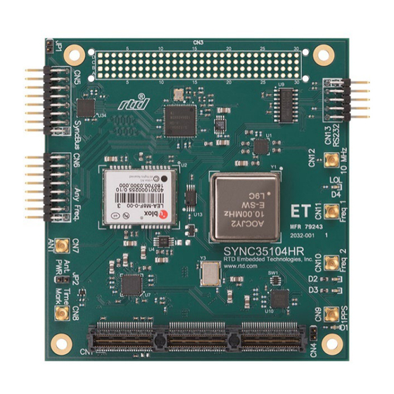
Product Overview The SYNC25104HR/SYNC35104HR is a GPS disciplined oscillator board which is designed to provide high accuracy frequency and time reference signals to PC/104 systems and external devices. This board utilizes the u-blox LEA-M8F GPS Receiver which locks the output signal of a low noise, high precision oven-controlled crystal oscillator (OCXO) to the GNSS satellites. -
Page 8: Board Features
2 differential outputs on the SyncBus connector (Bus LVDS) Software configurable output standard and frequency Differential: 100Hz-1028MHz LVCMOS (single-ended): 100Hz-250MHz Requires only +5 VDC for operation • SYNC35104HR RTD Embedded Technologies, Inc. | www.rtd.com SYNC25104HR/ User’s Manual... -
Page 9: Ordering Information
The Intelligent Data Acquisition Node (IDAN™) building block can be used in just about any combination with other IDAN building blocks to ® create a simple but rugged 104™ stack. This module can also be incorporated in a custom-built RTD HiDAN™ or HiDANplus High Reliability Intelligent Data Acquisition Node. -
Page 10: Contact Information
If you are having problems with you system, please try the steps in the Troubleshooting section of this manual. For help with this product, or any other product made by RTD, you can contact RTD Embedded Technologies technical support via the following methods: Phone: 1-814-234-8087 Monday through Friday, 8:00am to 5:00pm (EST). -
Page 11: Specifications
Output rise and fall time =5pF 0.35 RISE FALL Electrostatic discharge HBM ANSI/ESDA/JEDEC ±6000 (ESD) JS-001 Electrostatic discharge CBM JESD22-C101 ±1500 (ESD) CN10, CN11: Any frequency output (LVCMOS 3.3V) Output high voltage SYNC35104HR RTD Embedded Technologies, Inc. | www.rtd.com SYNC25104HR/ User’s Manual... - Page 12 Maximum data rate kbit/s High-level output voltage = 3 kΩ to GND Low-level output voltage = 3 kΩ to GND -5.4 Positive-going input voltage threshold Negative-going input voltage threshold Input voltage range SYNC35104HR RTD Embedded Technologies, Inc. | www.rtd.com SYNC25104HR/ User’s Manual...
-
Page 13: Board Connection
When removing it from the bag, hold the board at the edges, and do not touch the components or connectors. Handle the board in an antistatic environment and use a grounded workbench for testing and handling of your hardware. Physical Characteristics STEP model is available upon request; contact RTD Tech Support for more information. Weight: Approximately 80 g (0.18 lbs.) •... -
Page 14: Connectors And Jumpers
CN5: SyncBus Connector CN5 is a proprietary 16-pin header that is used for synchronizing RTD data acquisition and signal processing boards. The SyncBus Connector is a 2 x 8, 0.1” spacing right-angle connector. The lane assignments are shown in Table 5. A typical mating connector is an FCI 65043-029LF. -
Page 15: Cn6: Any Frequency Output
USB. When there is no transmission from the bus, the RX is switched to the RS232 TX input. RTS and DTR pins are not used and are pulled to GND with 10k. CTS is not connected. SYNC35104HR RTD Embedded Technologies, Inc. | www.rtd.com SYNC25104HR/... -
Page 16: Jumpers
10. Attach any necessary cables to the PC/104 stack. 11. Re-connect the power cord and apply power to the stack. 12. Boot the system and verify that all of the hardware is working properly. SYNC35104HR RTD Embedded Technologies, Inc. | www.rtd.com SYNC25104HR/ User’s Manual... -
Page 17: Figure 3: Example 104™Stack
Figure 3: Example 104™Stack SYNC35104HR RTD Embedded Technologies, Inc. | www.rtd.com SYNC25104HR/ User’s Manual... -
Page 18: Idan Connections
The PCIe connector is the connection to the system CPU. The position and pin assignments are compliant with the PCI/104-Express Specification. (See PC/104 Specifications on page 29) The SYNC25104HR is a “Universal” board and can connect to either a Type 1 or Type 2 PCIe/104 connector. SYNC35104HR RTD Embedded Technologies, Inc. | www.rtd.com SYNC25104HR/ User’s Manual... -
Page 19: External I/O Connectors
Figure 5: IDAN Front Panel Serial Connector - 9-pin “D” PIN Connector Connector Part #: Example Mating Connector: Amp VALCON DF-9P-CN 1658610-4 Table 9: IDAN-SYNC35104HR Serial Connector IDAN Pin# Signal(RS-232) (RS-232) SYNC25104HR Pin # CN13 RxD- CN13 TxD- CN13 CN13 CN13 CN13 TxD+... -
Page 20: Out2-5 Connector - 15-Pin "D" Socket Connector
Figure 6: IDAN Back Panel OUT2-5 Connector - 15-pin “D” Socket Connector Connector Part #: Example Mating Connector: Amp 1658610-3 1-747956-5 Table 10: IDAN-SYNC35104HR OUT2-5 Connector SYNC25104HR Pin # IDAN Pin# Signal Output 5+ OUTPUT 4+ OUTPUT 3+ OUTPUT 2+... -
Page 21: Steps For Installing
11. Re-connect the power cord and apply power to the stack. 12. Boot the system and verify that all of the hardware is working properly. Figure 7: Example IDAN System SYNC35104HR RTD Embedded Technologies, Inc. | www.rtd.com SYNC25104HR/ User’s Manual... -
Page 22: Functional Description
RS232 for timing purposes is highly recommended. The default configuration for the serial ports are: 9600 Baud • 8 Data bits • No parity • 1 Stop bit • No Flow Control • SYNC35104HR RTD Embedded Technologies, Inc. | www.rtd.com SYNC25104HR/ User’s Manual... -
Page 23: Gps Antenna
CN6 pin 9 (+), 10 (-) any differential OUT4 CN6 pin 5 (+), 6 (-) any differential OUT5 CN6 pin 1 (+), 2 (-) any differential OUT6 CN10 LVCMOS 3.3V SYNC35104HR RTD Embedded Technologies, Inc. | www.rtd.com SYNC25104HR/ User’s Manual... - Page 24 Otherwise, the initial phase of the output signals relative to the input signal will be random (obviously when the PLL is locked the phase difference will be constant, but random). SYNC35104HR RTD Embedded Technologies, Inc. | www.rtd.com SYNC25104HR/...
-
Page 25: Figure 8: Si5395 Block Diagram
Figure 9: SI5395 block diagram SYNC35104HR RTD Embedded Technologies, Inc. | www.rtd.com SYNC25104HR/ User’s Manual... -
Page 26: Software
6 Software Installing the Software The software package is provided on the SYNC35104HR companion CD and are also available on the RTD web site (http://www.rtd.com) for download. To install the software package please follow the detailed instructions found in the readme.txt file. -
Page 27: Syncbus Software
6.2.3 YNCBUS OFTWARE The syncbus outputs can be controlled with the syncbus_prog utility. SYNC35104HR RTD Embedded Technologies, Inc. | www.rtd.com SYNC25104HR/ User’s Manual... -
Page 28: Troubleshooting
If problems persist, or you have questions about configuring this product, contact RTD Embedded Technologies via the following methods: Phone: +1-814-234-8087 E-Mail: techsupport@rtd.com Be sure to check the RTD web site (http://www.rtd.com) frequently for product updates, including newer versions of the board manual and application software. SYNC35104HR RTD Embedded Technologies, Inc. | www.rtd.com SYNC25104HR/ User’s Manual... -
Page 29: Additional Information
A copy of the latest PC/104 specifications can be found on the webpage for the PC/104 Embedded Consortium: www.pc104.org PCI and PCI Express Specification A copy of the latest PCI and PCI Express specifications can be found on the webpage for the PCI Special Interest Group: www.pcisig.com SYNC35104HR RTD Embedded Technologies, Inc. | www.rtd.com SYNC25104HR/ User’s Manual... -
Page 30: Limited Warranty
During the one year warranty period, RTD Embedded Technologies will repair or replace, at its option, any defective products or parts at no additional charge, provided that the product is returned, shipping prepaid, to RTD Embedded Technologies. All replaced parts and products become the property of RTD Embedded Technologies. - Page 31 RTD Embedded Technologies, Inc. 103 Innovation Boulevard State College, PA 16803 USA Telephone: 814-234-8087 Fax: 814-234-5218 www.rtd.com sales@rtd.com techsupport@rtd.com Copyright 2022 by RTD Embedded Technologies, Inc. All rights reserved.
Need help?
Do you have a question about the SYNC25104HR and is the answer not in the manual?
Questions and answers