
Related Manuals for rtd cpuModule CMA22M Series


Summary of Contents for rtd cpuModule CMA22M Series
- Page 1 CMA22M cpuModules™ User’s Manual BDM-610000069 Revision A ® www.rtd.com An ISO9001:2000 Company “Accessing the Analog World” ®...
- Page 2 HiDAN, HiDANplus, “MIL Value for COTS prices”, multiPort, and PC/104EZ are trademarks, and “Accessing the Analog World”, dataModule, RTD, and the RTD logo are registered trademarks of RTD Embedded Technologies, Inc. PS/2, PC/XT, PC/AT, and IBM are trademarks of International Business Machines Inc. MS-DOS, Windows, Windows 95, Windows 98, and Windows NT are trademarks of Microsoft Corporation.
- Page 3 CMA22M cpuModules™ ® www.rtd.com An ISO9001:2000 Company “Accessing the Analog World” ®...
- Page 4 iv CMA22M cpuModule BDM-610000069 Rev A...
-
Page 5: Table Of Contents
Table of Contents Chapter 1 Introduction CMA22M cpuModules................. Enhanced Intel SpeedStep (Core 2 Duo only) . - Page 6 Configuring the RTD Enhanced AMI BIOS ........
- Page 7 Hardware Interrupts ................. . Non-Standard Serial Port Modes .
- Page 8 Physical Dimensions ................. . . Board Spacing .
-
Page 9: Chapter 1 Introduction
Troubleshooting offers advice on debugging problems with your system Appendix C IDAN™ Dimensions and Pinout provides connector pinouts for the cpuModule installed in an RTD Intelligent Data Acquisition Node (IDAN) frame Appendix D Additional Information lists sources and websites to support the cpuModule installation and configuration... -
Page 10: Cma22M Cpumodules
Advanced Digital I/O (aDIO), and Advanced Analog I/O (aAIO). RTD has gone the extra mile to include additional advanced features for maximum flexibility. These include a SATA Disk Chip socket that allows flash drive with a standard SATA interface to be attached to the board, either socketed or soldered. -
Page 11: Enhanced Intel Speedstep (Core 2 Duo Only)
Wake-on-aDIO RTD’s exclusive aDIO™ is 12 digital bits configured as 8 bit-direction programmable and 4-bit port-direction programmable I/O, plus 2 strobe inputs giving you any combination of inputs and outputs. Match, event, and strobe interrupt modes mean no more wasting valuable processor time polling digital inputs. - Page 12 The aAIO also provides interrupts on threshold crossing. A high and low threshold can be set for each channel. After sampling is started, an interrupt can be generated if any of the signals cross the threshold. This removes some of the CPU load for simple monitoring tasks. A DMA engine with a scatter-gather table allows efficient, robust handling of data.
-
Page 13: Ordering Information
CMA22MMCS1200HR-1024 Celeron (Single Core) 1.20 GHz, 1GB DDR2-SDRAM Cable Kits and Accessories For maximum flexibility, RTD does not provide cables with the cpuModule. You may wish to purchase the CMA22M cpuModule cable kit (P/N XK-CM91), which contains: • Multi-function utility harness (keyboard socket, battery, reset, speaker) •... -
Page 14: Board Features
Board Features • Penryn Processor Part Number Speed Cores L2 Cache FSB Speed CMA22MMVD1860 1.86GHZ 6 MB 1066 MHz CMA22MMVD1200 1.20 GHz 3 MB 800 MHz CMA22MMCS1200 1.20 GHz 1 MB 800 MHz – Intel 64 architecture for 64-bit processing. –... -
Page 15: I/O
– Supported power down modes: S1 (Power On Suspend), S3 (Suspend to RAM), S4 (Hibernate), and S5 (Soft-Off) – CPU Clock Throttling and Clock Stop for C0 to C6 Support – Wake events include: • aDIO Interrupt • Wake-on-LAN • Real Time Clock •... -
Page 16: Bios
Battery input for Real Time Clock • Power I/O – ATX Power signals BIOS • RTD Enhanced AMI BIOS • User-configurable using built-in Setup program • Nonvolatile storage of CMOS settings without battery • Boot Devices During the time of this manual’s publication, 8GB was the largest available SATA Disk Chip capacity... - Page 17 – Standard Devices (floppy disk, hard disk, etc.) – SATA Disk Chip – USB Device – Network – Fail Safe Boot ROM • Surface-mount Flash chip that holds ROM-DOS™ • Quick Boot mode BDM-610000069 Rev A Chapter 1: Introduction 9...
-
Page 18: Block Diagram
The cpuModule uses the RTD Enhanced AMI BIOS. Drivers in the BIOS allow booting from hard disk, Disk Chip, or boot block flash, thus enabling the system to be used with traditional disk drives or nonmechanical drives. -
Page 19: Specifications
2. 5V Standby is used to power the board when the main supply is turned off (power down modes S3-S5). It is not required for board operation. 3. With supplied heat sink solution. Depending on the CPU usage, performance may degrade as the ambient temperature approaches the maximum. Contact RTD Tech Support for more information. BDM-610000069 Rev A... -
Page 20: Electrical Characteristics
Electrical Characteristics The table below lists the Electrical Characteristics of the CMA22M. Operating outside of these parameters may cause permanent damage to the cpuModule. Table 4 Electrical Characteristics Symbol Parameter Test Condition Min. Max. Output Voltage High = –0.5 mA 2.9 V 3.3 V Output Voltage Low... - Page 21 Table 4 Electrical Characteristics Symbol Parameter Test Condition Min. Max. Serial Ports - RS-232 Output Voltage High = 3 k 5.0 V 10.0 V Output Voltage Low = 3 k -10.0 V -5.0 V Input Voltage High — 2.4 V 25 V Input Voltage Low —...
-
Page 22: Contact Information
Contact Information RTD Embedded Technologies, Inc. 103 Innovation Blvd. State College, PA 16803-0906 Phone: +1-814-234-8087 Fax: +1-814-234-5218 E-mail: sales@rtd.com techsupport@rtd.com Internet: http://www.rtd.com 14 CMA22M cpuModule BDM-610000069 Rev A... -
Page 23: Chapter 2 Getting Started
Chapter 2 Getting Started For many users, the factory configuration of the CMA22M cpuModule can be used to get a PC/104 system operational. You can get your system up and running quickly by following the simple steps described in this chapter, which are: Before connecting the cpuModule, the user must be properly grounded to prevent electrostatic discharge (ESD). -
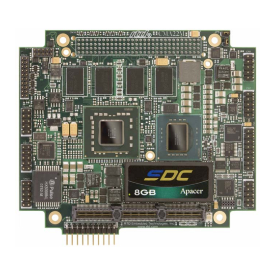
Page 24: Connector Locations
Connector Locations Figure 3 shows the connectors and the SATA Disk Chip socket of the CMA22M cpuModule. SVGA PCI Bus (CN16) Video (CN18) LVDS Flat COM2&4 Panel (CN8) (CN19) COM1&3 (CN7) aAIO (CN10) Switched (CN15) USB 2.0 (CN17) aDIO (CN6) Ethernet (CN20) Multi-... - Page 25 WARNING If you connect power incorrectly, the module will almost certainly be damaged or destroyed. Such damage is not covered by the RTD warranty! Please verify connections to the module before applying power. Power is normally supplied to the cpuModule through the PCIe and PCI bus connectors (CN1 or CN2, and CN16).
-
Page 26: Selecting The Stack Order For The Cma22M
The standard CPU has the PCI connection below the board only. This means that all boards with an active PCI bus interface must be below the CPU. Contact RTD sales if it is required to have a PCI board above the CPU. -
Page 27: Stack Example
Stack Example The figure below shows an example of a complete system stack. Most systems will be a subset of this example. This example stack may be further expanded with PCIe to PCIe bridges, a PCIe to PCI bridge, or a PCI to ISA bridge. -
Page 28: Connecting To The Stack
The PCI bus can operate at +3.3 V or +5 V signaling levels. The default PCI bus signaling level is +3.3 V. For more information, contact RTD Technical Support. WARNING You will have to ensure that all your expansion cards can operate together at a single signaling level. -
Page 29: Connecting The Utility Cable
Soft Power Button input To use these interfaces, you must connect to the utility port connector (CN5). The utility harness from the RTD cable kit provides a small speaker, two connectors for the keyboard and mouse, a push-button for resetting the system, a soft-power button, and a lithium battery to provide backup power for the real time clock. - Page 30 22 CMA22M cpuModule BDM-610000069 Rev A...
-
Page 31: Chapter 3 Connecting The Cpumodule
Chapter 3 Connecting the cpuModule This chapter provides information on all CMA22M cpuModule connectors. Proper Grounding Techniques—page 24 Connector Locations—page 24 Auxiliary Power (CN3)—page 26 Utility Port Connector (CN5)—page 27 SVGA Video Connector (CN18)—page 30 LVDS Flat Panel Video Connector (CN19)—page 31 SATA Disk Chip Socket (U16)—page 32 Serial Port 1 (CN7) and Serial Port 2 (CN8)—page 33 Advanced Digital I/O (aDIO™) Port (CN6)—page 38... -
Page 32: Proper Grounding Techniques
Proper Grounding Techniques Before removing the CMA22M from its static bag, proper grounding techniques must be used to prevent electrostatic discharge (ESD) damage to the cpuModule. Common grounding procedures include an anti-static mat on a workbench, which may connect to an anti-static wrist strap (also known as an ESD wrist strap) on the wrist of the technician or engineer. - Page 33 Table 6 CMA22M Basic Connectors Connector Function Size and Pitch Mating Connector Express Platform Bus (Top) 156-pin, 0.635mm Samtec ASP-129646-03 PCIe/104 Bus (Bottom) 156-pin, 0.635mm Samtec ASP-129637-03 Auxiliary Power 1x10, 0.1” FCI 65039-027LF Utility Port 2x5, 0.1” 3M 89110-0001 aDIO 2x8, 0.1”...
-
Page 34: Auxiliary Power (Cn3)
Auxiliary Power (CN3) The Auxiliary Power connector (CN3) can be used to supply power to devices that are attached to the cpuModule. These devices include hard drive, front-end boards for data acquisition systems, and other devices. Power can also be conveyed to the module through the Auxiliary Power connector (CN3). The cpuModule only requires +5 V and ground for operation. -
Page 35: Utility Port Connector (Cn5)
Utility Port Connector (CN5) The utility port connector implements the following functions: • PC/AT compatible keyboard port • PS/2 mouse port • Speaker port (0.1W output) • Hardware Reset input • Soft Power Button input • Battery input for Real Time Clock Table 8 provides the pinout of the multi-function connector. -
Page 36: Keyboard
Keyboard A PS/2 compatible keyboard can be connected to the multi-function connector. Usually PC keyboards come with a cable ending with a 5-pin male PS/2 connector. Table 9 lists the relationship between the multi-function connector pins and a standard PS/2 keyboard connector. Table 9 Keyboard Connector Pins (CN5) Signal Function... -
Page 37: Battery
Battery Pin 9 of the multi-function connector is the connection for an external backup battery. This battery is used by the cpuModule when system power is removed in order to preserve the date and time in the real time clock. Connecting a battery is only required to maintain time when power is completely removed from the cpuModule. -
Page 38: Svga Video Connector (Cn18)
SVGA Video Connector (CN18) Table 11 provides the pinout of the video connector. Table 11 SVGA Video Connector (CN18) Signal Function In/Out VSYNC Vertical Sync HSYNC Horizontal Sync DDCSCL Monitor Communications Clock Red Analog Output DDCSDA Monitor Communications Data bidirectional GREEN Green Analog Output +5 V... -
Page 39: Lvds Flat Panel Video Connector (Cn19)
Table 12 provides the pinout of the Flat Panel Video connector (CN19). FP_VCC is configured for +3.3V by default. Contact RTD to have FP_VCC configured for +5 V. FP_VBKLT can be either +5 V or +12 V, and can be selected with JP9. -
Page 40: Sata Disk Chip Socket (U16)
SATA Disk Chip Socket (U16) The SATA Disk Chip socket is an 18-pin socket in a 32-pin format that supports miniature SATA flash disk chips. The socket allows a true SATA device to be attached to the board with either a socketed or soldered connection. Such devices are supported by all major operating systems, and do not require special drivers. -
Page 41: Serial Port 1 (Cn7) And Serial Port 2 (Cn8)
Serial Port 1 (CN7) and Serial Port 2 (CN8) Serial Port 1 (COM1) is implemented on connector CN7, and Serial Port 2 is implemented on connector CN8. The serial ports are normally configured as PC compatible full-duplex RS-232 ports, but you may use the BIOS Setup program to reconfigure these ports as half-duplex RS-422 or full-duplex RS-422 or RS-485. -
Page 42: Rs-422 Or Rs-485 Serial Port
Facing the serial port’s connector pins, the pinout is: RS-422 or RS-485 Serial Port You may use Setup to configure the serial ports as RS-422 or RS-485. In this case, you must connect the serial port to an RS-422 or RS-485 compatible device. When using RS-422 or RS-485 mode, you can use the serial ports in either half-duplex (two-wire) or full-duplex (four-wire) configurations. -
Page 43: Rs-422 And Rs-485 Mode Pinout
RS-422 and RS-485 Mode Pinout Table 19 provides the serial port connector pinout when RS-422 or RS-485 modes are enabled. Table 19 Serial Port in RS-422/485 Mode Signal Function In/Out DB-9 — Reserved — — Reserved — RXD– Receive Data (–) TXD+ Transmit Data (+) TXD–... -
Page 44: Dual Serial Port Modes
Dual Serial Port Modes The serial port connectors can be configured as dual serial ports in the BIOS. The mapping between the connectors and COM port numbers is shown in Table 20. The supported combinations of serial port modes are listed in Table 21, which also includes a reference to the corresponding connector pinout. - Page 45 Table 23 COM A (RS-422/485) and COM B (RS-232) Signal Function In/Out DB-9 DCD1 COM A - Data Carrier Detect RXD2 COM B - Receive Data RXD1- COM A - Receive Data (–) TXD1+ COM A - Transmit Data (+) TXD1- COM A - Transmit Data (–) RXD1+...
-
Page 46: Advanced Digital I/O (Adio™) Port (Cn6)
Advanced Digital I/O (aDIO™) Port (CN6) CN6 is configured as an aDIO port. aDIO is 12 digital bits configured as 8-bit programmable and 4-bit port programmable I/O, providing any combination of inputs and outputs. Match, event, and strobe interrupt modes mean no more wasting valuable processor time polling digital inputs. -
Page 47: Advanced Analog I/O (Aaio™) Port (Cn10)
Advanced Analog I/O (aAIO™) Port (CN10) The Advanced Analog I/O connector provides eight channels of analog input. When used in conjunction with the aDIO port, it allows the cpuModule to be a complete single-board data acquisition system. For more information on using the aAIO port, consult the aAIO Programming Manual. Table 26 aAIO Pinout CN6 Pin Function... -
Page 48: Usb 2.0 Connector (Cn17)
Two USB 2.0 compliant connectors are available on connector CN17. Table 27 provides the pinout of the USB connector. Note For proper operation at USB 2.0 speeds, be sure to use a cable that is rated for USB 2.0, such as the cable kit supplied by RTD. Table 27 USB Connector (CN17) Signal... -
Page 49: Ethernet (10/100/1000Base-T And -Tx) Connector (Cn20)
Ethernet (10/100/1000Base-T and -TX) Connector (CN20) This connector provides a 10/100/1000Base-T Ethernet connection. Table 28 provides the pinout of the Ethernet connector. For 1000Base-T, all four pairs are used for transmit and receive. To use the onboard 10/100/1000 Ethernet controller, Ethernet must first be enabled in the BIOS. When enabled, the multi-color LED will blink to indicate an Ethernet connection. -
Page 50: Express Platform Bus (Cn1) (Top-Type 2)
Express Platform Bus (CN1) (Top-Type 2) Connector CN1 carries the signals of the Express Platform bus. The signals on the first bank match definitions found in the PCI/104-Express & PCIe/104 Specification Version 1.1 from the PC/104 Embedded Consortium. The signals on the second and third bank are used for SATA hard drive carrier expansion. Table 29 lists the pinouts of the PC/104-Express bus connector. - Page 51 Table 29 Express Platform Bus Signal Assignments (Top View) Signal Signal Reserved Reserved Reserved Reserved Reserved Reserved Reserved Reserved Reserved Reserved Reserved Reserved Reserved Reserved Reserved Reserved Reserved Reserved SATA_0Rp SATA_0Tp SATA_0Rn SATA_0Tn SATA_1Rp SATA_1Tp SATA_1Rn SATA_1Tn Reserved Reserved Reserved Reserved Reserved Reserved...
-
Page 52: Express Platform Compatibility
Table 29 Express Platform Bus Signal Assignments (Top View) Signal Signal Reserved Reserved Reserved Reserved Reserved Reserved Reserved Reserved Reserved Reserved Reserved Reserved Reserved Reserved Reserved Reserved Reserved Reserved Reserved Reserved Reserved Reserved Reserved Reserved Reserved Reserved Reserved Reserved Reserved Reserved Reserved Reserved... -
Page 53: Pcie Link Configuration
PCIe Link Configuration This cpuModule supports a total of eight PCIe x1 links. The chipset, however, only provides five PCIe x1 links. Four of the links on CN1 and CN2 are connected directly to the chipset. The other four are connected through a PCIe packet switch, and share the bandwidth of a single x1 link back to the chipset. -
Page 54: Pci/104-Express Pcie Bus (Cn2) (Bottom-Type 1)
PCI/104-Express PCIe Bus (CN2) (Bottom-Type 1) Connector CN2 carries the signals of the PCI/104-Express PCIe bus. These signals match definitions found in the PCI/104-Express & PCIe/104 Specification Version 1.1 from the PC/104 Embedded Consortium. Table 31 lists the pinouts of the PC/104-Express bus connector. WARNING Not all PCIe cards are compatible with the PCIe (Type 1) connector. - Page 55 Table 31 PC/104-Express Bus Signal Assignments (Top View) Signal Signal WAKE# n.c. PEx16_0T(8)p PEx16_0T(0)p PEx16_0T(8)n PEx16_0T(0)n PEx16_0T(9)p PEx16_0T(1)p PEx16_0T(9)n PEx16_0T(1)n PEx16_0T(10)p PEx16_0T(2)p PEx16_0T(10)n PEx16_0T(2)n PEx16_0T(11)p PEx16_0T(3)p PEx16_0T(11)n PEx16_0T(3)n PEx16_0T(12)p PEx16_0T(4)p PEx16_0T(12)n PEx16_0T(4)n PEx16_0T(13)p PEx16_0T(5)p PEx16_0T(13)n PEx16_0T(5)n PEx16_0T(14)p PEx16_0T(6)p PEx16_0T(14)n PEx16_0T(6)n PEx16_0T(15)p PEx16_0T(7)p PEx16_0T(15)n...
-
Page 56: Pci/104-Express Pcie Bus Signals
Table 31 PC/104-Express Bus Signal Assignments (Top View) Signal Signal SDVO_DAT/PENA SDVO_CLK PEx16_0R(8)p PEx16_0R(0)p PEx16_0R(8)n PEx16_0R(0)n PEx16_0R(9)p PEx16_0R(1)p PEx16_0R(9)n PEx16_0R(1)n PEx16_0R(10)p PEx16_0R(2)p PEx16_0R(10)n PEx16_0R(2)n PEx16_0R(11)p PEx16_0R(3)p PEx16_0R(11)n PEx16_0R(3)n PEx16_0R(12)p PEx16_0R(4)p PEx16_0R(12)n PEx16_0R(4)n PEx16_0R(13)p PEx16_0R(5)p PEx16_0R(13)n PEx16_0R(5)n PEx16_0R(14)p PEx16_0R(6)p PEx16_0R(14)n PEx16_0R(6)n PEx16_0R(15)p PEx16_0R(7)p PEx16_0R(15)n... -
Page 57: Pcie Link Configuration
The signals on the x16 link can also be used for additional outputs from the Integrated Graphics Device. Contact RTD tech support for more details. PCIe Link Configuration This cpuModule supports a total of eight PCIe x1 links. The chipset, however, only provides five PCIe x1 links. -
Page 58: Pc/104-Plus Pci Bus (Cn16)
PC/104-Plus PCI Bus (CN16) Connector CN16 carries the signals of the PC/104-Plus PCI bus. These signals match definitions of the PCI Local Bus specification Revision 2.1. Table 33 list the pinouts of the PC/104-Plus bus connector. Table 33 PC/104-Plus Bus Signal Assignments +5V_STDBY +5 V AD00... -
Page 59: Pc/104-Plus Pci Bus Signals
PC/104-Plus PCI Bus Signals The following are brief descriptions of the PC/104-Plus PCI bus signals. Address and Data AD[31:00] — Address and Data are multiplexed. A bus transaction consists of an address cycle followed by one or more data cycles. C/BE[3:0]# —... -
Page 60: Power Supplies And Vio
–12 V — –12 V supply connected to the PC/104 bus and Auxiliary Power Connector (CN3) –12 V supplies. +3.3 V — The +3.3 V pins on the PC/104-Plus (PCI) connector are connected to the Auxiliary Power Connector (CN3) by default. To supply +3.3V via the onboard +3.3V power supply, contact RTD Technical Support. -
Page 61: Optional Rtc Battery Input (Cn13)
Optional RTC Battery Input (CN13) The optional RTC battery input is the connection for an external backup battery. This battery is used by the cpuModule when system power is removed in order to preserve the date and time in the real time clock. Connecting a battery is only required to maintain time when power is completely removed from the cpuModule. - Page 62 54 CMA22M cpuModule BDM-610000069 Rev A...
-
Page 63: Chapter 4 Using The Cpumodule
This chapter provides information for users who wish to develop their own applications programs for the CMA22M cpuModule. This chapter includes information on the following topics: The RTD Enhanced AMI BIOS —page 56 Memory Map—page 58 I/O Address Map—page 59 Hardware Interrupts—page 60... -
Page 64: The Rtd Enhanced Ami Bios
The RTD Enhanced AMI BIOS The RTD Enhanced AMI BIOS is software that interfaces hardware-specific features of the cpuModule to an operating system (OS). Physically, the BIOS software is stored in a Flash EPROM on the cpuModule. Functions of the BIOS are divided into two parts. -
Page 65: Main Menu Setup Fields
Main Menu Setup Fields The following is a list of Main Menu Setup fields. Table 37 Main Menu Setup Fields Field Active Keys Selections Main Press Enter to select Access system information such as BIOS version, EPLD version, and CMOS time and date settings Advanced Press Enter to select Setup advanced cpuModule features... -
Page 66: Memory Map
Memory Map Table 38 shows how memory in the first megabyte is allocated in the system. Table 38 First Megabyte Memory Map Address (hex) Description C0000–FFFFFh ROM 256 KB BIOS in Flash EPROM, shadowed into DRAM during runtime. C0000–EFFFFh Run time user memory space. Usually, memory between C0000h and CFFFFh is used for the BIOS of add-on VGA video cards. -
Page 67: I/O Address Map
I/O Address Map As with all standard PC/104 boards, the I/O total I/O space is 64k in size. However, because early processors only addressed 0 address lines (SA0–SA9), the first 1k is used for legacy I/O devices. Any ISA add-on modules you install must therefore use I/O addresses in the range of 0–1023 (decimal) or 000–3FF (hex). -
Page 68: Hardware Interrupts
Hardware Interrupts Note If you add any expansion modules or other peripherals to the system, you must ensure they do not use interrupts needed by the cpuModule, or malfunctions will occur. The CMA22M cpuModule supports the standard PC interrupts listed in Table 40. Interrupts not in use by hardware on the cpuModule itself are listed as available. -
Page 69: Non-Standard Serial Port Modes
Non-Standard Serial Port Modes It is possible to change the input clock rate for the UARTs of the cpuModule by selecting the Serial Port Baud Rates option in the Serial Port Configuration menu of the BIOS Setup. Changing the option from Normal to Non-Standard will allow the serial port to operate at higher speeds. -
Page 70: Advanced Digital I/O Ports (Adio™)
This board supports 12 bits of TTL/CMOS compatible digital I/O (TTL signaling). These I/O lines are grouped into two ports, Port 0 and Port 1. Port 0 is bit programmable; Port 1 is byte programmable. Port 0 supports RTD’s Advanced Digital Interrupt modes. The three modes are strobe, match and event. Strobe mode generates an interrupt and latches Port 0 when the strobe input transitions from low to high. - Page 71 Table 45 DIO-Control I/O Address 9C3h—Read Access Strobe 1 Status Strobe 0 Status 0 = no strobe 0 = no strobe Multi-Function 1 = strobe Digital IRQ Mode 1 = strobe Register Select 00 = Disabled 00 = clear mode 01 = strobe Mode Digital IRQ Status Port 1 Direction...
-
Page 72: Port 1 Data Register Is A Read/Write Byte Direction
Table 48 Wake Control I/O Address 9C4h Reserved Int Mask Wake Enable 1 = Interrupt is masked 1=Interrupt triggers a Wake Event 0=Interrupt is enabled 0=Interrupt does not trigger a wake event. Port 1 Data register is a read/write byte direction Interrupts In order to use an interrupt with aDIO, the interrupt must first be selected in the BIOS setup utility under Advanced, I/O Devices, aDIO Configuration, aDIO Interrupt. -
Page 73: Strobe Mode
Figure 6 aDIO Match Mode Strobe Mode Another interrupt mode supported by aDIO is Strobe mode. This allows the strobe pin of the DIO connector to trigger an interrupt. A low to high transition on the strobe pin will cause an interrupt request. The request will remain high until the Clear Register is read from. -
Page 74: Real Time Clock Control
This RTD cpuModule uses onboard flash to store user BIOS settings. To preserve compatibility with traditional PCs, the RTD Enhanced BIOS also mirrors the user settings from flash in CMOS. Therefore, the contents of CMOS may be overwritten at boot time, and should be treated as “read only”. - Page 75 Altering the contents of any unlisted RTC register may interfere with the operation of your cpuModule. The specific uses of the unlisted RTC registers will depend on the BIOS version loaded on the cpuModule. Contact RTD's technical support for more information. BDM-610000069 Rev A...
-
Page 76: Watchdog Timer Control
The Advanced Watchdog Timer has a Setup Register and a Runtime Register. The Setup Register is set by the BIOS, and can be adjusted by entering the BIOS Setup Utility, and going to “Advanced/Miscellaneous RTD Features”. The Setup Register may also be read by the driver to determine if the Watchdog is enabled, and the interrupt and base address that it is using. -
Page 77: Thermal Management
Thermal Management The cpuModule has several thermal features which can be used to monitor and control the board’s temperature when extreme operating conditions are prevalent. Thermal Monitor The Intel ® Thermal Monitor is a feature on the CMA22M that automatically throttles the CPU when the CPU exceeds its thermal limit. -
Page 78: Power Management
Power Management The CMA22M cpuModule supports various powering mechanisms which allow the cpuModule to monitor power consumption and temperature, and achieve minimal power consumption states. These unique features include Enhanced Intel® SpeedStep® Technology (Core 2 Duo only), thermal monitoring and thermal throttling, as well as low power modes including ACPI configurations. -
Page 79: At Vs. Atx Power Supplies
• Resume on PME#: When enabled, the system can wake when a signal is applied to the PME# signal on the PCI bus, or the WAKE# signal on the PCIe bus. This includes wake-up on onboard LAN controller. • Resume on RTC Alarm: The RTC Alarm allows the system to turn on at a certain time every day. AT vs. -
Page 80: Multi-Color Led
Multi-Color LED The CMA22M has a Multi-Color LED which can be enabled or disabled in the BIOS setup screen. The color of the LED indicates the status of the board, as shown in Table 53. Table 53 LED Colors Color Description Green Normal Operation... -
Page 81: Reset Status Register
Reset Status Register The cpuModule has several different signals on board which can cause a system reset. If a reset occurs, the reset status register can be used to see which reset or resets have been asserted on the cpuModule. The user has the ability to see which resets have been asserted. - Page 82 Table 58 Reset Status Description and Priorities I/O Address Reset Reset Description 457h Signal Priority Utility Reset Utility connector push button reset CPU Core Power CPU core powers supply System Power Power supplies that are not for standby power SIO Power Power monitored by the Super I/O.
-
Page 83: Features And Settings That Can Affect Boot Time
ROMs. During POST, the BIOS executes the card's extension code. This extension code is third-party code, which is beyond RTD's control. The BIOS extension will most likely increase the boot time. Exactly how much it increases boot time will depend on the particular card and firmware version. -
Page 84: System Recovery
(i.e. pin 7 is the transmit pin). The port settings are 115kbps, 8 bits, no parity, one stop bit. When using this recovery mode, the POST codes can be logged on another computer running terminal software. Contact RTD technical support for more details. BIOS Boot Block Recovery This recovery mode allows you to re-load a BIOS that has been corrupted. -
Page 85: Appendix A Hardware Reference
Appendix A Hardware Reference This appendix provides information on CMA22M cpuModule hardware, including: Jumper Settings and Locations—page 78 Onboard PCI Devices—page 80 Physical Dimensions—page 81 BDM-610000069 Rev A Appendix A: Hardware Reference 77... -
Page 86: Jumper Settings And Locations
Jumper Settings and Locations Many cpuModule options are configured by positioning jumpers. Jumpers are labeled on the board as JP followed by a number. Some jumpers have three pins, allowing three settings: • Pins 1 and 2 connected (indicated as “1–2”) •... - Page 87 Figure 7 CMA22M Jumper Locations (top side) Table 60 CMA22M Jumpers Jumper Pins Function Default Reserved open Reserved open Select power for flat panel backlight (bottom side) pins 2–3 pins 1–2: +12 V pins 2–3: +5 V BDM-610000069 Rev A Appendix A: Hardware Reference 79...
-
Page 88: Onboard Pci Devices
Onboard PCI Devices The CMA22M cpuModule has several onboard PCI devices, all of which are listed in the table below. This table shows a typical configuration, and the actual devices may change based on BIOS settings. Table 61 Onboard PCI Devices Device ID Vendor ID Description... -
Page 89: Physical Dimensions
Physical Dimensions Figure 8 shows the mechanical dimensions of the CMA22M cpuModule. Figure 8 CMA22M Physical Dimensions (±0.005 inches) Board Spacing In order to facilitate larger heatsink solutions, the CMA22M is designed to use a 22mm standoff between it and the board above it. - Page 90 82 CMA22M cpuModule BDM-610000069 Rev A...
- Page 91 Appendix B Troubleshooting Many problems you may encounter with operation of your CMA22M cpuModule are due to common errors. This appendix includes the following sections to help you get your system operating properly. Common Problems and Solutions—page 84 Troubleshooting a PC/104 System—page 85 How to Obtain Technical Support—page 86 BDM-610000069 Rev A Appendix B: Troubleshooting 83...
-
Page 92: Common Problems And Solutions
Table 62 lists some of the common problems you may encounter while using your CMA22M cpuModule, and suggests possible solutions. If you are having problems with your cpuModule, review this table before contacting RTD Technical Support. Table 62 Troubleshooting Problem... -
Page 93: Troubleshooting A Pc/104 System
Table 62 Troubleshooting (cont’d) Problem Cause Solution • keyboard does not work keyboard interface damaged check if keyboard LEDs light by misconnection • wrong keyboard type verify keyboard is an “AT” type or switch to “AT” mode • floppy drive light always on cable misconnected check for floppy drive cable connected backwards •... -
Page 94: How To Obtain Technical Support
List of settings from cpuModule Setup program • Printout of autoexec.bat and config.sys files (if applicable) • Description of problem • Circumstances under which problem occurs Then contact RTD Technical Support: Phone: 814-234-8087 Fax: 814-234-5218 E-mail: techsupport@rtd.com 86 CMA22M cpuModule BDM-610000069 Rev A... -
Page 95: Appendix Cidan™ Dimensions And Pinout
RTD modules installed in IDAN frames are called building blocks. IDAN building blocks maintain the simple but rugged stacking concept of PC/104 and PC/104-Plus. Each RTD module is mounted in its own IDAN frame and all I/O connections are brought to the walls of each frame using standard PC connectors. No... -
Page 96: Idan Dimensions And Connectors
IDAN Dimensions and Connectors 6-pin mini-DIN (female) 9-pin D (male) module P/N: Adam Tech MDE006W module P/N: Adam Tech DE09PD mating P/N: Adam Tech MDP006 mating P/N: Adam Tech DE09SD 25-pin D (female) module P/N: Adam Tech DB25SD mating P/N: Adam Tech DB25PD FRONT 9-pin D (male) 20-pin mini D (female) -
Page 97: External I/O Connections
External I/O Connections Table 63 PS/2 Mouse — 6-Pin mini-DIN Connector (female) IDAN Pin # Signal Function MDAT Mouse Data Reserved — Ground +5 V +5 Volts MCLK Mouse Clock Reserved — Table 64 Keyboard — 6-Pin mini-DIN Connector (female) IDAN Pin # Signal Function... - Page 98 Table 65 COM1/COM2 (RS-232) — 9-Pin D Connector (male) IDAN Pin # Signal Function Mode Data Carrier Detect Input Receive Data Input Transmit Data Output Data Terminal Ready Output Ground — Data Set Ready Input Request To Send Output Clear To Send Input Ring Indicator Input...
- Page 99 Table 67 aDIO — 25-Pin D Connector (female) IDAN Pin # aDIO Port CPU Pin # P0-0 P0-2 P0-4 P0-6 Strobe 0 P1-0 P1-2 reserved reserved reserved reserved reserved P0-1 P0-3 P0-5 P0-7 Strobe 1 P1-1 P1-3 +5 V reserved reserved reserved reserved...
- Page 100 Table 68 aAIO — 9-Pin D Connector (male) IDAN Pin # aAIO Port CPU Pin # Channel 1 Channel 3 Channel 5 Channel 7 Channel 2 Channel 4 Channel 6 Channel 8 Table 69 Panel — 20-Pin mini D Connector (female) IDAN Pin # Signal Name CPU Pin #...
- Page 101 Table 70 SVGA — 15-Pin High Density D Connector (female) IDAN Pin # Signal Function CPU Pin # Red Analog Output Green Green Analog Output Blue Blue Analog Output Reserved Reserved — Ground Ground Ground Ground +5 V + 5 Volts Ground Reserved Reserved...
- Page 102 Table 71 USB — 9-Pin D Connector (male) IDAN Pin # Signal Function Mode VCC1 +5 V to USB1 output Data USB1– USB1 Data– input/output Data USB1+ USB1 Data+ input/output Ground — Ground — VCC2 +5 V to USB2 output Data USB2–...
-
Page 103: Appendix D Additional Information
For the latest application notes, refer to the RTD website. Drivers and Example Programs To obtain the latest versions of drivers and example programs for this cpuModule, refer to the RTD website. Interrupt Programming For more information about interrupts and writing interrupt service routines, refer to the following book:... - Page 104 96 CMA22M cpuModule BDM-610000069 Rev A...
-
Page 105: Appendix E Limited Warranty
RTD Embedded Technologies, Inc. warrants the hardware and software products it manufactures and produces to be free from defects in materials and workmanship for one year following the date of shipment from RTD Embedded Technologies, Inc. This warranty is limited to the original purchaser of product and is not transferable. - Page 106 98 CMA22M cpuModule BDM-610000069 Rev A...
Need help?
Do you have a question about the cpuModule CMA22M Series and is the answer not in the manual?
Questions and answers