
Related Manuals for rtd CMA34KB


Summary of Contents for rtd CMA34KB
- Page 1 CMX34KB / CMA34KB User’s Manual BDM-610000089 Revision B www.rtd.com ISO9001 and AS9100...
- Page 2 Contents and specifications within this manual are given without warranty and are subject to change without notice. RTD Embedded Technologies, Inc. shall not be liable for errors or omissions in this manual, or for any loss, damage, or injury in connection with the use of this manual.
- Page 4 CMX34KB / CMA34KB ® www.rtd.com ISO9001 and AS9100...
- Page 5 Revision History Revision Date Reason for Change 9/7/2021 Initial release 5/15/2024 Corrected CN3 connector description and mating connector model. Added CMA34KB version of cpuModule...
-
Page 6: Table Of Contents
Connecting to the Stack ....................... 33 Power Input Connections ......................33 Connecting to the Utility Port 2.0 Connector ................34 Booting the CMX34KB/CMA34KB cpuModule for the First Time ........34 Chapter 3 Connecting the cpuModule ......... 35 Proper Grounding Techniques ....................36 Connector Locations ........................ - Page 7 Fan Connector (CN12) ........................57 Chapter 4 Using the cpuModule ............ 58 The RTD Enhanced BIOS ......................59 Configuring the RTD Enhanced BIOS ..................59 Entering the BIOS Setup through the Graphical BIOS Menu ............. 59 Field Selection ..........................61 Main Menu Setup Fields ........................
- Page 8 Monitor Type ........................... 77 System Recovery ........................... 78 Reset Button Recovery ........................78 Load Default BIOS Settings ......................78 Serial Power-On-Self-Test (POST) Code Output ................. 78 Appendix A Hardware Reference ..........79 CMX34KB / CMA34KB User’s Manual BDM-610000089 Rev B...
- Page 9 Application Notes ......................... 99 Drivers and Example Programs ....................99 Interrupt Programming ......................99 Serial Port Programming ......................99 PC/104 Specifications........................99 Appendix E Limited Warranty ............. 100 Appendix E Limited Warranty CMX34KB / CMA34KB User’s Manual BDM-610000089 Rev B...
- Page 10 CMX34KB / CMA34KB User’s Manual BDM-610000089 Rev B...
-
Page 11: Chapter 1 Introduction
® Appendix C IDAN Dimensions and Pinout provides connector pinouts for the cpuModule installed in an RTD Intelligent Data Acquisition Node (IDAN) frame Appendix D Additional Information lists sources and websites to support the cpuModule installation and configuration... -
Page 12: Cmx34Kb/Cma34Kb Cpumodules
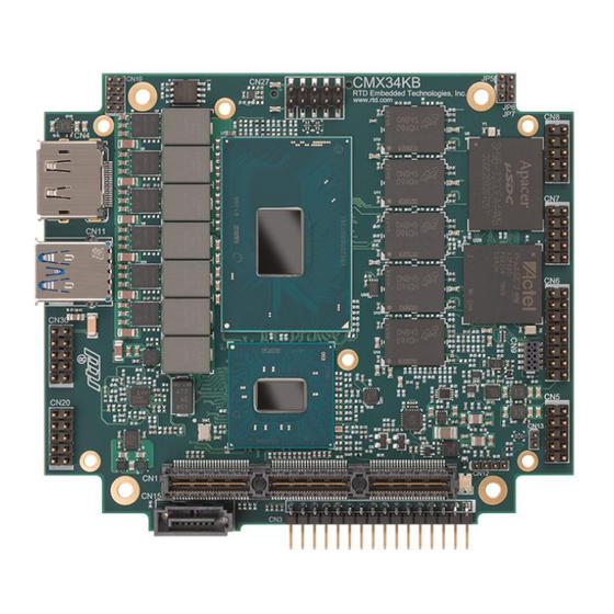
10-pin DIL headers for a total of four USB 2.0 ports. The CMX34KB as one 10-pin DIL header for two USB 2.0 ports and one USB Type A receptacle for one USB 3.0 port. Both the CMX34KB and CMA34KB cpuModules have an additional USB 2.0 port routed to the Utility Port for use of a keyboard and mouse. - Page 13 Figure 1 CMX34KB cpuModule (top view) Figure 2 CMA34KB cpuModule (top view) CMX34KB/CMA34KB User’s Manual BDM-610000089 Rev B...
-
Page 14: Adio
The cpuModule uses the RTD Enhanced BIOS. Functionality in the BIOS allows booting from hard disk, UEFI shell, USB, or network booting. The cpuModule and BIOS are compatible with any real-time operating systems for PC compatible computers, although these may require creation of custom drivers to use the aDIO and watchdog timer. -
Page 15: Ordering Information
PC/104 systems. CMX34KB/CMA34KB Model Options The basic cpuModule model options are shown below. Refer to the RTD website (www.rtd.com) for more detailed ordering information and any new variations that may be available. RTD also offers customer custom modifications. Contact RTD Sales for details. -
Page 16: Cable Kits And Accessories
The CMX34KB has a USB Type A receptacle for USB 3.0, CN11. Cable Kits and Accessories For maximum flexibility, RTD does not provide cables with the cpuModule. You may wish to purchase the CMX34KB/CMA34KB cpuModule cable kit (XK-CM113), which contains: •... -
Page 17: Board Features
Thermal Monitor throttles processor and memory to prevent thermal runaway – Modified heatsinks and flat heat spreaders are available – Mini Fan Heatsink with Auto Fan control – Passive Structural Heatsink & Heat Pipes in IDAN and HiDAN System Configurations CMX34KB/CMA34KB User’s Manual BDM-610000089 Rev B... -
Page 18: I/O
USB Boot capability – Three ports on 0.1” I/O headers: two on CN27, and one on CN5 – The CMA34KB has two additional USB 2.0 ports at CN17. The CMX34KB has one USB 3.0 port at CN11. CMX34KB/CMA34KB User’s Manual BDM-610000089... - Page 19 USB Boot capability – On CN11, a USB A connector • Automatic resettable over-current protection (750 mA @ 5 Vdc) • Not included on the CMA34KB • Serial ATA (SATA) – Six SATA revision 3.0 links • Two links to the top-side PCIe connector •...
-
Page 20: Rtd Enhanced Bios
Supports boot from SATA, USB, or Network • UEFI (Unified Extensible Firmware Interface) Shell • Special RTD Enhancements Block Diagram The next figure shows a simplified block diagram of the CMX34KB cpuModule. Figure 2 CMX34KB cpuModule Simplified Block Diagram CMX34KB/CMA34KB User’s Manual BDM-610000089 Rev B... - Page 21 The following figure shows a simplified block diagram of the CMA34KB cpuModule. Figure 3 CMA34KB cpuModule Simplified Block Diagram CMX34KB/CMA34KB User’s Manual BDM-610000089 Rev B...
-
Page 22: Specifications
Power Consumption Exact power consumption depends on the actual application. Typical power consumption of the CMX34KB/CMA34KB is listed in Table 3. It is expected that power consumption of a typical application will be a combination of these scenarios. Table 2... -
Page 23: Operating Conditions
1. With supplied heat sink solution. Depending on the CPU usage, performance may degrade as the ambient temperature approaches the maximum. Contact RTD Tech Support for more information. 2. Calculation Model: Telcordia Issue 2; Calculation Method: Method 1 Case 3; Temperature: +30C; Environment: Ground Benign, Controlled CMX34KB/CMA34KB User’s Manual... -
Page 24: Electrical Characteristics
Electrical Characteristics The table below lists the Electrical Characteristics of the CMX34KB/CMA34KB. Operating outside of these parameters may cause permanent damage to the cpuModule. Table 4 Electrical Characteristics Min. Max. Symbol Parameter Test Condition USB Ports Overcurrent Limit Each Port USB2.0 0.51 A 0.75 A... - Page 25 1. Date and time lost when power is completely removed from the system including the CMOS battery. Date and time are not required for board operation. BIOS will set default values on the next power cycle. CMX34KB/CMA34KB User’s Manual BDM-610000089 Rev B...
-
Page 26: Migrating To Rtd's Intel Xeon Series Cpumodules
Complete information about the connectors on the CMX34KB/CMA34KB can be found in Chapter 3, Connecting the cpuModule. New I/O Connectors on the CMX34KB The CMX34KB cpuModule introduces a new I/O connector that was not present on some previous RTD cpuModules: •... -
Page 27: Software Differences
Previous generations of RTD cpuModules contained a Failsafe Boot ROM image, which permitted the cpuModule to boot to a DOS prompt even when no disk drives were connected to the system. The RTD Xeon Series cpuModules provide a similar prompt, called the Unified Extensible Firmware Interface (UEFI) Shell, which provides an environment to execute simple commands when no bootable devices are connected to the system. -
Page 28: Contact Information
Contact Information RTD Embedded Technologies, Inc. 103 Innovation Blvd. State College, PA 16803-0906 Phone: +1-814-234-8087 Fax: +1-814-234-5218 E-mail: sales@rtd.com techsupport@rtd.com rma@rtd.com Internet: http://www.rtd.com CMX34KB/CMA34KB User’s Manual BDM-610000089 Rev B... -
Page 29: Chapter 2 Getting Started
Chapter 2 Getting Started For many users, the factory configuration of the CMX34KB/CMA34KB cpuModule can be used to get a PC/104 system operational. You can get your system up and running quickly by following the simple steps described in this chapter, which are: Before connecting the cpuModule, the user must be properly grounded to prevent electrostatic discharge (ESD). -
Page 30: Connector Locations
Connector Locations Figure 3 and Figure 4 show the connectors of the CMX34KB and CMA34KB cpuModules, respectively. Figure 3 CMX34KB cpuModule (top view) USB 2.0 Factory Use (CN27) (CN10) COM2&4 (CN8) DisplayPort (CN4) COM1&3 (CN7) USB 3.0 (CN11) Ethernet aDIO... -
Page 31: Selecting The Stack Order For The Cmx34Kb/Cma34Kb
Selecting the Stack Order for the CMX34KB/CMA34KB There are several things to consider when selecting the order of boards in the stack. Before selecting the order, be sure to determine which bus connector on each board is the “Active” bus. Typically, if a peripheral module has both PCIe and PCI bus connectors, only the PCIe is active, and the PCI is pass-through. -
Page 32: Stack Example
The figure below shows an example of a complete system stack. Most systems will be a subset of this example. This example stack may be further expanded with PCIe-to-PCIe bridges or a PCIe to PCI bridge. Figure 4 System Stacking Example CMX34KB/CMA34KB User’s Manual BDM-610000089 Rev B... -
Page 33: Connecting To The Stack
Power to the board must come from either the top or bottom PCIe/104 Type 2 bus connectors (CN1 or CN2), or the auxiliary power connector (CN3). These connectors provide the required +12V DC voltage rail input to the cpuModule. CMX34KB/CMA34KB User’s Manual BDM-610000089 Rev B... -
Page 34: Connecting To The Utility Port 2.0 Connector
To use these interfaces, you must connect to the Utility Port 2.0 connector (CN5). The Utility Port 2.0 cable from the RTD cable kit provides a small speaker, two USB 2.0 ports for a keyboard and mouse, a push-button for resetting the system, a soft-power button, and a lithium battery to provide backup power for the real time clock. -
Page 35: Chapter 3 Connecting The Cpumodule
Chapter 3 Connecting the cpuModule This chapter provides information on all CMX34KB/CMA34KB cpuModule connectors. Proper Grounding Techniques – Page 36 Connector Locations – Page 36 Auxiliary Power (CN3) – Page 38 Utility Port 2.0 Connector (CN5) – Page 40 DisplayPort Connector (CN4) – Page 42 Serial Port 1 (CN7) and Serial Port 2 (CN8) –... -
Page 36: Proper Grounding Techniques
Proper Grounding Techniques Before removing the CMX34KB/CMA34KB from its static bag, proper grounding techniques must be used to prevent electrostatic discharge (ESD) damage to the cpuModule. Common grounding procedures include an anti-static mat on a workbench, which may connect to an anti-static wrist strap (also known as an ESD wrist strap) on the wrist of the technician or engineer. - Page 37 Figure 6 shows the connectors of the CMA34KB cpuModule. Factory Use (CN10) COM2&4 DisplayPort (CN8) (CN4) COM1&3 USB 3.0 (CN7) (CN11) Ethernet aDIO (CN20) (CN6) Utility Port 2.0 Ethernet (CN5) (CN20) Battery (CN13) PCIe/104 Bus SATA Auxiliary Power (CN1 Top and CN2 Bottom)
-
Page 38: Auxiliary Power (Cn3)
3M 89110-0001 CN30 Only on CMX34KB. Replaces CN17. Only on CMA34KB. Replaces CN11. Auxiliary Power (CN3) The Auxiliary Power connector (CN3) can be used to supply power to devices that are attached to the cpuModule. These devices include hard drive, front-end boards for data acquisition systems, and other devices. - Page 39 +12 V +12 Volts DC Ground WARNING The user is responsible for any over-voltage and reverse voltage protection that would be necessary to power through CN3. Over-voltage damage at CN3 is not covered under warranty. CMX34KB/CMA34KB User’s Manual BDM-610000089 Rev B...
-
Page 40: Utility Port 2.0 Connector (Cn5)
Shield Ground WARNING The pinout of the Utility Port 2.0 connector is not compatible with some older generations of RTD cpuModules. Attaching a legacy Utility Port harness to the Utility Port 2.0 connector may damage or destroy the cpuModule. Facing into the connector pins, the pinout is shown in the table below: (pin one is indicated by a square... -
Page 41: Usb 2.0 Connector
Connecting a battery is only required to maintain time when power is completely removed from the cpuModule. A battery is not required for board operation. WARNING The optional RTC battery input connector (CN13) should be left unconnected if the multi-function connector (CN5) has a battery connected to pin 9. CMX34KB/CMA34KB User’s Manual BDM-610000089 Rev B... -
Page 42: Displayport Connector (Cn4)
DisplayPort Connector (CN4) The DisplayPort connector on the CMX34KB/CMA34KB cpuModule is a standard PC DisplayPort connector complete with latch holes to provide a rugged connecting solution for latching DisplayPort cables. The DisplayPort supports all mandatory features of the VESA DisplayPort (DP) 1.4 standard and supports audio over the connection. - Page 43 Facing the connector pins of the DisplayPort connector (CN4), the pinout is: AUX- AUX+ CFG1 LN2- LN2+ LN0- LN0+ CFG2 LN3- LN3+ LN1- LN1+ CMX34KB/CMA34KB User’s Manual BDM-610000089 Rev B...
-
Page 44: Serial Port 1 (Cn7) And Serial Port 2 (Cn8)
Signal Function In/Out DB-25 DB-9 Data Carrier Detect Data Set Ready Receive Data Request To Send Transmit Data Clear To Send Data Terminal Ready Ring Indicate — Signal Ground — — — Signal Ground CMX34KB/CMA34KB User’s Manual BDM-610000089 Rev B... -
Page 45: Rs-422 Or Rs-485 Serial Port
Full-Duplex Connections Port 1 Port 2 RXD+ TXD+ TXD+ RXD+ RXD– TXD– TXD– RXD– In RS-485 mode, the connection of the ports is always half-duplex, as the transceivers’ transmitters are connected to the receivers internally. CMX34KB/CMA34KB User’s Manual BDM-610000089 Rev B... - Page 46 Facing the serial port connector, the pinout is: RXD- RXD+ TXD+ TXD- Rsvd Rsvd Rsvd Rsvd WARNING The pinout of the COM ports in RS-422 mode is not compatible with some older generations of RTD cpuModules. CMX34KB/CMA34KB User’s Manual BDM-610000089 Rev B...
- Page 47 Rsvd WARNING The pinout of the COM ports in RS-485 mode is not compatible with some older generations of RTD cpuModules. Note When using the serial port in RS-485 mode, the serial transmitters are enabled and disabled under software control. The transmitters can be enabled by manipulating the Request To Send (RTS*) signal of the serial port controller.
-
Page 48: Dual Serial Port Modes
1. Dual RS-485 mode with echo uses dual RS-422 mode pinout WARNING The dual serial port mode pinouts of the COM ports are not compatible with some older generations of RTD cpuModules. Note The cpuModule has 120 Ohm termination resistors. Termination is usually necessary on all RS-422 receivers and at the ends of the RS-485 bus. - Page 49 COM B - Data (–) in/out COM A - Data (+) in/out COM B - Data (+) in/out — — Reserved — — Reserved — — Reserved — — Reserved — Signal Ground — — Signal Ground CMX34KB/CMA34KB User’s Manual BDM-610000089 Rev B...
-
Page 50: Advanced Digital I/O (Adio™) Port (Cn6)
Table 21 aDIO Pinout CN6 Pin Function CN6 Pin Function P0-0 P0-1 P0-2 P0-3 P0-4 P0-5 P0-6 P0-7 strobe 0 strobe 1 P1-0 P1-1 P1-2 P1-3 +5 V 1. Available during standby. (CN6) Pin 1 CMX34KB/CMA34KB User’s Manual BDM-610000089 Rev B... -
Page 51: Ethernet (10/100/1000Base-T And -Tx) Connector (Cn20, Cn30)
B+ (RX+) Receive+ (10/100) B- (RX–) Receive– (10/100) A+ (TX+) Transmit+ (10/100) A- (TX–) Transmit– (10/100) — AGND Ethernet Ground — AGND Ethernet Ground AGND AGND D– A– C– B– (CN20, CN30) Pin 1 CMX34KB/CMA34KB User’s Manual BDM-610000089 Rev B... -
Page 52: Pcie/104 Type 2 Bus (Cn1 - Top And Cn2 - Bottom)
+3.3V +3.3V USB_1p USB_0p USB_1n USB_0n PEx1_1Tp PEx1_0Tp PEx1_1Tn PEx1_0Tn PEx1_2Tp PEx1_3Tp PEx1_2Tn PEx1_3Tn PEx1_1Rp PEx1_0Rp PEx1_1Rn PEx1_0Rn PEx1_2Rp PEx1_3Rp PEx1_2Rn PEx1_3Rn PEx1_1Clkp PEx1_0Clkp PEx1_1Clkn PEx1_0Clkn +5V_STBY +5V_STBY PEx1_2Clkp PEx1_3Clkp PEx1_2Clkn PEx1_3Clkn CPU_DIR PWRGOOD CMX34KB/CMA34KB User’s Manual BDM-610000089 Rev B... - Page 53 WAKE# STK1 PEx4_1T(0)P PEx4_0T(0)P PEx4_1T(0)N PEx4_0T(0)N PEx4_1T(1)P PEx4_0T(1)P PEx4_1T(1)N PEx4_0T(1)N PEx4_1T(2)P PEx4_0T(2)P PEx4_1T(2)N PEx4_0T(2)N PEx4_1T(3)P PEx4_0T(3)P PEx4_1T(3)N PEx4_0T(3)N SATA_T1_P SATA_T0_P SATA_T1_N SATA_T0_N USB3_T1_P USB3_T0_P USB3_T1_N USB3_T0_N Reserved Reserved Reserved Reserved Reserved Reserved Reserved Reserved CMX34KB/CMA34KB User’s Manual BDM-610000089 Rev B...
- Page 54 1. Signals marked with (#) are active low. 2. +3.3V is not required for board operation. For power input requirements, see Table 3. 12V Blade 5V Blade 5V Blade Figure 6 Locations of 5V and 12V Power Blades CMX34KB/CMA34KB User’s Manual BDM-610000089 Rev B...
-
Page 55: Pcie/104 Type 2 Compatibility
PCIe links are split between the top-side PCIe/104 connector (CN1) and bottom-side PCIe/104 connector (CN2) as seen in Table 25. Table 25 PCIe Link Configuration Link Connector Number of Links Width per Connector CN1, CN2 CN1, CN2 CMX34KB/CMA34KB User’s Manual BDM-610000089 Rev B... -
Page 56: Optional Rtc Battery Input (Cn13)
Utility Port 2.0 connector (CN5) has a battery connected. (CN13) Pin 1 SATA 3.0 (CN15) CN15 is a SATA 3.0 connection direct to the PCH. USB 2.0 Connector (CN27) (CN27) Pin 1 CMX34KB / CMA34KB User’s Manual BDM-610000089 Rev B... -
Page 57: Usb 2.0 Connector (Cn17)
USB 3.0 Connector (CN11) Populated on the CMX34KB only. The Type A receptacle is USB 3.0. Fan Connector (CN12) For factory use. Do not connect anything but the RTD supplied fan for the cpuModule. CMX34KB / CMA34KB User’s Manual BDM-610000089... -
Page 58: Chapter 4 Using The Cpumodule
This chapter provides information for users who wish to develop their own applications programs for the CMX34KB cpuModule. This chapter includes information on the following topics: The RTD Enhanced BIOS – Page 59 Operating System Specific Usage – Page 62 Non-Standard Serial Port Modes –... -
Page 59: The Rtd Enhanced Bios
The RTD Enhanced BIOS The RTD Enhanced BIOS is software that interfaces hardware-specific features of the cpuModule to an operating system (OS). Physically, the BIOS software is stored in a Flash EPROM on the cpuModule. Functions of the BIOS are divided into two parts. - Page 60 Table 27 Graphical BIOS Menu Options Function Traditional BIOS Setup CMX34KB / CMA34KB User’s Manual BDM-610000089 Rev B...
-
Page 61: Field Selection
WARNING Incorrect modifications to the BIOS can cause your system to break. If you are unsure of any changes made to the BIOS, there is a Load RTD Defaults option under the Exit tab in the SCU. This option restores the BIOS to the default factory settings. -
Page 62: Operating System Specific Usage
(most notably SATA), and may not work as expected. At the time of publication, RTD has validated Ubuntu 20.04, OpenSuse 13.2, and OpenSuse LEAP 15.0. However, any standard PC Linux distribution with a 4.10 or newer kernel is expected to work. -
Page 63: Non-Standard Serial Port Modes
Maximum Baud Rate Multiplier 0x0E28 115,200 0x38A0 460,800 0x713F 921,600 0x7AE1 1,000,000 8.7x Note When using the non-standard high speed serial port modes, it is highly recommended to use hardware flow control, whenever possible. CMX34KB / CMA34KB User’s Manual BDM-610000089 Rev B... -
Page 64: Advanced Digital I/O Ports (Adio™)
TTL/CMOS compatible digital I/O (TTL signaling). These I/O lines are grouped into two ports, Port 0 and Port 1. Port 0 is bit programmable; Port 1 is byte programmable. Port 0 supports RTD’s Advanced Digital Interrupt modes. The three modes are strobe, match, and event. Strobe mode generates an interrupt and latches Port 0 when the strobe input transitions from low to high. - Page 65 00 clear 01 ion 01 Port Dir 0 in, 1 out 0 no mask, 1 10 DIO mask mask 11 compare read/write 1. Contents based on bits D0 and D1 of DIO-Control. CMX34KB / CMA34KB User’s Manual BDM-610000089 Rev B...
-
Page 66: Interrupts
Interrupt. The Digital I/O can use interrupts 3, 5, 6, 10, and 11. To configure the aDIO interrupt, navigate to the BIOS Setup option, the “Advanced”, “RTD aDIO”, and “aDIO Interrupt” menu options. The BIOS will automatically reserve the selected interrupt so that is it not assigned to PCI devices. Then, select the appropriate interrupt mode in the DIO Control register. - Page 67 Compare Register is made. You must read the Compare Register, and then clear interrupts so that the latched value in the compare register is not lost. To enter Strobe mode, set bits [4:3] of the DIO-Control register to “01”. CMX34KB / CMA34KB User’s Manual BDM-610000089 Rev B...
-
Page 68: Sata Controller Configuration
SATA Controller Configuration The CMX34KB/CMA34KB has six SATA 3.0 links with transfer speeds up to 6 Gbps. Two SATA links reside on the top PCIe/104 Type 2 connector (CN1), and two SATA links reside on the bottom PCIe/104 Type 2 connector (CN2). The remaining SATA links connect to the onboard SATA storage drive and to the SATA connector, CN15. -
Page 69: Watchdog Timer Control
The Advanced Watchdog Timer has a Setup Register and a Runtime Register. The Setup Register is set by the BIOS and can be adjusted by entering the BIOS Setup Utility, and going to “Advanced”, “RTD Advanced Options”, “RTD Miscellaneous Feature Control”. The Setup Register may also be read by the driver to determine if the Watchdog is enabled, and the interrupt and base address that it is using. -
Page 70: Thermal Management
Upon entering the Critical Trip state, the operating system will issue a command to the processor, and the CMX34KB/CMA34KB will immediately transition to the S5 (Soft-Off) ACPI power state. To exit the Critical Trip state (and S5), the CPU temperature must be reduced to a point that the internal thermal sensors are below the Critical Trip Point. -
Page 71: Power Management
Power Management The CMX34KB/CMA34KB cpuModule supports various powering mechanisms which allow the cpuModule to monitor power consumption and temperature and achieve minimal power consumption states. These unique features include thermal monitoring and thermal throttling, as well as ACPI low power modes. Various wake options are also available to resume normal system power. -
Page 72: At Vs. Atx Power Supplies
AT vs. ATX Power Supplies Both AT and ATX power supplies may be used with the CMX34KB/CMA34KB cpuModule, however AT power supplies do not provide any standby power to the cpuModule. When an AT power supply is used to power the system, low power modes that require a standby power to wake the system will not be fully supported. -
Page 73: Multi-Color Led
Multi-Color LED The CMX34KB/CMA34KB has a Multi-Color LED which can be enabled or disabled in the BIOS setup screen. The color of the LED indicates the status of the board, as shown in Table 42. Table 42 LED Colors Color... -
Page 74: Reset And Event Status Register
Memory Pwr PwrGood Vgfx 1 = reset asserted 1 = reset asserted Good 1 = reset asserted 0 = no reset 0 = no reset 1 = reset asserted 0 = no reset CMX34KB / CMA34KB User’s Manual BDM-610000089 Rev B... - Page 75 1 = reset asserted 0 = no reset 0 = no reset Utility Reset Reserved Reserved Bus Stack Error 1 = reset asserted 1 = reset asserted 0 = no reset 0 = no reset CMX34KB / CMA34KB User’s Manual BDM-610000089 Rev B...
-
Page 76: Trusted Platform Module
Trusted Platform Module The CMX34KB/CMA34KB cpuModule includes a Trusted Platform Module (TPM) that is fully compliant to the Trusted Computing Group (TCG) TPM version 2.0 specification. TPM stands for “Trusted Platform Module”. The TPM is a controller on your cpuModule that provides tamper resistant storage using hardware-based cryptography. -
Page 77: Features And Settings That Can Affect Boot Time
ROMs. During POST, the BIOS executes the card's extension code. This extension code is third-party code, which is beyond RTD's control. The BIOS extension will most likely increase the boot time. Exactly how much it increases boot time will depend on the particular card and firmware version. -
Page 78: System Recovery
It is also a good starting point when making BIOS changes. After restoring defaults, the BIOS settings should be reviewed and modified as needed. The default BIOS can be restored either by using Reset Button Recovery, or the “Load RTD Defaults” option in the BIOS. -
Page 79: Appendix A Hardware Reference
Appendix A Hardware Reference This appendix provides information on CMX34KB/CMA34KB cpuModule hardware, including: Jumper Settings and Locations – Page 80 Onboard PCI/PCIe Devices – Page 81 Physical Dimensions – Page 82 Heatsink Dimensions – Page 83 Flat-Heatspreader Dimensions – Page 84 CMX34KB / CMA34KB User’s Manual... -
Page 80: Jumper Settings And Locations
Figure 8 shows the jumper locations that are used to configure the cpuModule. Table 51 lists the jumpers and their settings. Both the CMX34KB and the CMA34KB have the same jumpers and jumper settings. Figure 8... -
Page 81: Onboard Pci/Pcie Devices
Onboard PCI/PCIe Devices The CMX34KB/CMA34KB cpuModule has several onboard PCI/PCIe devices, all of which are listed in the table below. This table shows a typical configuration, and the actual devices may change based on BIOS settings. Table 52 Onboard PCI/PCIe Devices... -
Page 82: Physical Dimensions
Physical Dimensions Figure 9 CMX34KB/CMA34KB Physical Dimensions (±0.005 inches) 1. Both CMX34KB and CMA34KB have the same dimensions CMX34KB / CMA34KB User’s Manual BDM-610000089 Rev B... -
Page 83: Heatsink Dimensions
0.866” (22mm) Figure 10 0.866” (22mm) 2.1 GHz CMA34KBD2100HR-16384/S60GX Figure 11 0.866” (22mm) 2.2 GHz CMA34KBQ2200HR-16384/S60GX Figure 11 0.866” (22mm) 3.0 GHz Figure 11 CMA34KBQ3000HR-16384/S60GX Edge near PCIe/104 Connector Figure 10 CMX34KB Heatsink CMX34KB / CMA34KB User’s Manual BDM-610000089 Rev B... -
Page 84: Flat-Heatspreader Dimensions
For cooling solutions where it is desirable to mount the cpuModule to a flat surface, the CMX34KB/CMA34KB may be ordered with a flat heatspreader instead of the standard passive heatsink. Each flat-heatspreader has five mounting locations which use 6-32 UNC x 0.207” long threaded insert. - Page 85 Edge near PCIe/104 Connector Figure 13 CMX34KB 0.866” (22mm) Flat-Heatspreader Edge near PCIe/104 Connector CMA34KB 0.866” (22mm) Flat-Heatspreader Figure 14 CMX34KB / CMA34KB User’s Manual BDM-610000089 Rev B...
-
Page 86: Appendix B Troubleshooting
Appendix B Troubleshooting Many problems you may encounter with operation of your CMX34KB/CMA34KB cpuModule are due to common errors. This appendix includes the following sections to help you get your system operating properly. Common Problems and Solutions – Page 87 Troubleshooting a PC/104 System –... -
Page 87: Common Problems And Solutions
Common Problems and Solutions Table 55 lists some of the common problems you may encounter while using your CMX34KB/CMA34KB cpuModule and suggests possible solutions. If you are having problems with your cpuModule, review this table before contacting RTD Technical Support. -
Page 88: Troubleshooting A Pc/104 System
If you have reviewed the preceding table and still cannot isolate the problem with your CMX34KB/CMA34KB cpuModule, please try the following troubleshooting steps. Even if the resulting information does not help you find the problem, it will be very helpful if you need to contact technical support. -
Page 89: How To Obtain Technical Support
List of settings from cpuModule Setup program • Printout of autoexec.bat and config.sys files (if applicable) • Description of problem • Circumstances under which problem occurs Then contact RTD Technical Support: Phone: 814-234-8087 Fax: 814-234-5218 E-mail: techsupport@rtd.com CMX34KB / CMA34KB User’s Manual BDM-610000089 Rev B... -
Page 90: Appendix C Idan Dimensions And Pinout
IDAN frame and all I/O connections are brought to the walls of each frame using standard PC connectors. On the CMA34KB, no connections are made from module to module internal to the system other than through the PCIe/104 Type 2 bus, enabling quick interchangeability and system expansion without hours of rewiring and board redesign. -
Page 91: Idan Contents
2.5” SATA interface to the first SATA link on the CPU’s top PCIe/104 Type 2 connector (CN1). Also, inside the IDAN-CMA34KB unit is a CMOS battery which is connected to the battery input connection of the cpuModule’s Utility Port 2.0 connector. The frame of the IDAN-CMA34KB brings out the cpuModule’s multi-color LED as well as the cpuModule’s reset button. -
Page 92: Idan Dimensions
For more information on cpuModule’s battery input and reset button input on the Utility Port 2.0 connector, refer to the Utility Port 2.0 Connector (CN5) on page 40. IDAN Dimensions The IDAN frame for the CMA34KB is shown in the figure below: SATA34106 Back Panel 2.5”... -
Page 93: Idan Connector Locations
The diagrams below show the connector locations for the headers of the IDAN-CMA34KB as they are brought out on the front and back panels of the IDAN-CMA34KB. For a full description of each connector on the IDAN-CMA34KB, refer to Connecting the cpuModule on page 35. There is not an IDAN- CMX34KB at this time. - Page 94 9-pin D (male) Adam Tech DE09PD Adam Tech DE09SD CN27 USB 2.0 9-pin D (male) Adam Tech DE09PD Adam Tech DE09SD CN20 and Ethernet 9-pin D (male) Adam Tech DE09PD Adam Tech DE09SD CN30 CMX34KB / CMA34KB User’s Manual BDM-610000089 Rev B...
-
Page 95: External I/O Connections
Table 58 COM1/COM2 (Dual Port Mode)— 9-Pin D Connector (male) CPU Pin IDAN Dual Dual Dual RS-232 RS-422 RS-485 (DB-9) DCD1 TXD1- RXD1 TXD1+ — TXD1 RXD1+ — RTS1 RXD1- CTS1 TXD2- TXD2 TXD2+ — RXD2 RXD2+ — RXD2- CMX34KB / CMA34KB User’s Manual BDM-610000089 Rev B... - Page 96 — P0-1 — P0-3 — P0-5 — P0-7 — Strobe 1 — P1-1 — P1-3 — +5 V — — reserved — — reserved — Push-Button Reset Input — RTC Battery Input CMX34KB / CMA34KB User’s Manual BDM-610000089 Rev B...
- Page 97 Return for DPV +3.3V DC Power +3.3V DC Power Requires special passive adapter 2.HDMI mode only Facing DisplayPort connector, the pinout is: AUX- AUX+ CFG1 LN2- LN2+ LN0- LN0+ CFG2 LN3- LN3+ LN1- LN1+ CMX34KB / CMA34KB User’s Manual BDM-610000089 Rev B...
- Page 98 Data USB1- USB1 Data– Input/Output Data USB1+ USB1 Data+ Input/Output – – Shield GND Shield GND VCC2 +5V to USB2 Output Data USB2- USB2 Data– Input/Output Data USB2+ USB2 Data+ Input/Output – CMX34KB / CMA34KB User’s Manual BDM-610000089 Rev B...
-
Page 99: Appendix D Additional Information
For the latest application notes, refer to the RTD website. Drivers and Example Programs To obtain the latest versions of drivers and example programs for this cpuModule, refer to the RTD website. Interrupt Programming For more information about interrupts and writing interrupt service routines, refer to the following book:... -
Page 100: Appendix E Limited Warranty
Under no circumstances will RTD Embedded Technologies be liable to the purchaser or any user for any damages, including any incidental or consequential damages, expenses, lost profits, lost savings, or other damages arising out of the use or inability to use the product.
Need help?
Do you have a question about the CMA34KB and is the answer not in the manual?
Questions and answers