
Related Manuals for rtd CAN SPIDER


Summary of Contents for rtd CAN SPIDER
- Page 1 CAN SPIDER CAN Bus Hub User’s Manual BDM-610040004 Rev. D RTD Embedded Technologies, Inc. AS9100 and ISO 9001 Certified...
- Page 2 RTD Embedded Technologies, Inc. 103 Innovation Boulevard State College, PA 16803 USA Telephone: 814-234-8087 Fax: 814-234-5218 www.rtd.com sales@rtd.com techsupport@rtd.com...
- Page 3 Failure to follow the instructions found in this manual may result in damage to the product described in this manual, or other components of the system. The procedure set forth in this manual shall only be performed by persons qualified to service electronic equipment. Contents and specifications within this manual are given without warranty, and are subject to change without notice. RTD Embedded Technologies, Inc. shall not be liable for errors or omissions in this manual, or for any loss, damage, or injury in connection with the use of this manual.
-
Page 4: Table Of Contents
Block Diagram................................... 13 CAN Bus ....................................13 Power ......................................15 4.3.1 +8 to + 36 Input Volt Power Supply 4.3.2 +5 Volt Isolated Supply Troubleshooting Additional Information PC/104 Specifications ................................17 Limited Warranty | www.rtd.com BRG2110 User’s Manual RTD Embedded Technologies, Inc. - Page 5 Figure 4 J5 pin one location seen from top ................................11 Figure 5: Example 104™Stack ....................................12 Figure 6: CAN SPIDER Block Diagram .................................. 13 Figure 7 CANSpider Application Example ................................14 Figure 8 CANSpider Standalone Application Example ............................15 Table of Tables Table 1: Ordering Options ......................................
-
Page 6: Introduction
Product Overview This manual gives information on the CAN Spider active CAN bus hub. The CAN Spider can connect up to four fiber optic ECAN527-2 PC/104 CAN bus interface boards together. Other CAN bus devices may be connected to the galvanically isolated twisted pair CAN port. This structure enables flexible expansion of CAN Spiders as well as connection of twisted pair CAN devices to your network. -
Page 7: Specifications
Note: The fiber optic transceivers are classified as IEC 825-1 Accessible Emission Limit (AEL) Class 1 based upon the current proposed draft scheduled to go to effect on January 1, 1997. AEL Class 1 LED devices are considered eye safe. | www.rtd.com BRG2110 User’s Manual RTD Embedded Technologies, Inc. -
Page 8: Board Connection
Physical Characteristics • Weight: Approximately 100 g (0.22 lbs.) • Dimensions: 90.17 mm L x 95.89 mm W (3.550 in L x 3.775 in W) Figure 1: Board Dimensions | www.rtd.com BRG2110 User’s Manual RTD Embedded Technologies, Inc. -
Page 9: Connectors And Jumpers
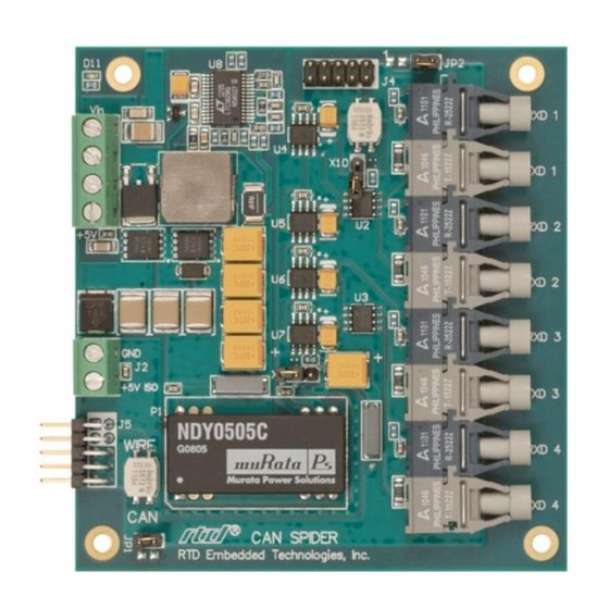
TXD1 to TXD4 – Fiber Transmitter outputs 3.3.2 ONNECTORS The CAN Spider is physically PC/104 size with the same mounting holes, but it does not have a bus connector. 3.3.3 UMPERS On all jumpers, pin 1 is designated by a thick white silkscreen line, and a square pad on the PCB. -
Page 10: X10: Can Bus Termination
JP2 is used to provide isolated +5V to CAN bus connector J4 pin 8. Table 7: JP2 Settings Setting Description 1-2 Shorted Isolated +5V on CAN bus connector J4 pin 8 (Default) 1-2 Open J4 pin 8 open | www.rtd.com BRG2110 User’s Manual RTD Embedded Technologies, Inc. -
Page 11: Can Connectors
CAN H JP5: CAN connector Figure 4 J5 pin one location seen from top Table 9: J5 Pinout. Pin number Pin Name CAN L Pin number Pin Name 5V ISO CAN H | www.rtd.com BRG2110 User’s Manual RTD Embedded Technologies, Inc. -
Page 12: Steps For Installing
10. Attach any necessary cables to the PC/104 stack. 11. Re-connect the power cord and apply power to the stack. 12. Boot the system and verify that all of the hardware is working properly. Figure 5: Example 104™Stack | www.rtd.com BRG2110 User’s Manual RTD Embedded Technologies, Inc. -
Page 13: Functional Description
Functional Description Block Diagram The Figure below shows the functional block diagram of the CAN SPIDER. The various parts of the block diagram are discussed in the following sections. Figure 6: CAN SPIDER Block Diagram CAN Bus The CANSpider active CAN bus hub can connect up to four fiber optic CAN devices, such as RTD’s ECAN527-2 PC/104 CAN bus interface boards together. -
Page 14: Figure 7 Canspider Application Example
Figure 7 CANSpider Application Example | www.rtd.com BRG2110 User’s Manual RTD Embedded Technologies, Inc. -
Page 15: Power
Figure 8 CANSpider Standalone Application Example Power The main power input to the CAN Spider is 8 – 36 volts. The board makes +5V and isolated +5V as described below. 4.3.1 + 36 I NPUT OWER UPPLY The main power input is 8 – 36 volts on J1. This input is converted to 25 watts of +5 volts. This power is used to power the isolated +5 volt supply and is available on J1 for external devices. -
Page 16: Troubleshooting
If problems persist, or you have questions about configuring this product, contact RTD Embedded Technologies via the following methods: Phone: +1-814-234-8087 E-Mail: techsupport@rtd.com Be sure to check the RTD web site (http://www.rtd.com) frequently for product updates, including newer versions of the board manual and application software. | www.rtd.com BRG2110 User’s Manual RTD Embedded Technologies, Inc. -
Page 17: Additional Information
Additional Information PC/104 Specifications A copy of the latest PC/104 specifications can be found on the webpage for the PC/104 Embedded Consortium: www.pc104.org | www.rtd.com BRG2110 User’s Manual RTD Embedded Technologies, Inc. -
Page 18: Limited Warranty
During the one year warranty period, RTD Embedded Technologies will repair or replace, at its option, any defective products or parts at no additional charge, provided that the product is returned, shipping prepaid, to RTD Embedded Technologies. All replaced parts and products become the property of RTD Embedded Technologies. - Page 19 RTD Embedded Technologies, Inc. 103 Innovation Boulevard State College, PA 16803 USA Telephone: 814-234-8087 Fax: 814-234-5218 www.rtd.com sales@rtd.com techsupport@rtd.com Copyright 2021 by RTD Embedded Technologies, Inc. All rights reserved.
Need help?
Do you have a question about the CAN SPIDER and is the answer not in the manual?
Questions and answers