Table of Contents
Advertisement
Quick Links
Advertisement
Table of Contents
Troubleshooting

Related Manuals for rtd CNV36JXNX


Summary of Contents for rtd CNV36JXNX
- Page 1 CNV36JXNX cpu/gpuModules™ User’s Manual BDM-610000090 Revision A ® www.rtd.com...
- Page 2 Contents and specifications within this manual are given without warranty and are subject to change without notice. RTD Embedded Technologies, Inc. shall not be liable for errors or omissions in this manual, or for any loss, damage, or injury in connection with the use of this manual.
- Page 3 CNV36JXNX cpu/gpuModules™ www.rtd.com...
-
Page 4: Table Of Contents
Selecting the Stack Order for the CNV36JXNX ............20 Connecting to the Stack ..................... 21 Power Input Connections ....................21 Booting the CNV36JXNX cpu/gpuModule for the First Time ........21 Chapter 3 Connecting the cpu/gpuModule ........22 Connector Locations ......................23 Auxiliary Power (CN3) ...................... - Page 5 IDAN Contents ........................57 IDAN Dimensions ....................... 57 IDAN Connectors ....................... 58 External I/O Connections ....................60 Appendix D Additional Information ..........63 NVIDIA Driver Information: ..................... 63 PC/104 Specifications......................63 Appendix E Limited Warranty ............64 CNV36JXNX User’s Manual BDM-610000090 Rev A...
-
Page 6: Chapter 1 Introduction
Troubleshooting offers advice on debugging problems with your system IDAN™ Dimensions and Pinout Appendix C provides connector pinouts for the cpu/gpuModule installed in an RTD Intelligent Data Acquisition Node (IDAN) frame Appendix D Additional Information lists sources and websites to support the cpu/gpuModule installation and configuration... -
Page 7: Cnv36Jxnx Cpu/Gpumodule
The Jetson Xavier NX has a 16GB eMMC 5.1 Flash storage device, a microSD socket is also available on the CNV36JXNX carrier for expansion. M.2 NVMe/PCIe based SSDs can also be used with the board either by means of the M.2 B-key socket or by using additional carrier board (SSD34200/SSD34100). The onboard M.2 B-key socket only has USB3.1 and PCIe X1 interfaces. - Page 8 Refer to Appendix C IDAN™ Dimensions and Pinout, for more information. The CNV36JXNX cpu/gpuModule can also be purchased as part of a custom-built RTD HiDAN™ or HiDANplus High Reliability Intelligent Data Acquisition Node. Contact RTD for more information on its high reliability PC/104 systems.
-
Page 9: Cnv36Jxnx Model Options
CNV36JXNX Model Options The basic cpu/gpuModule model options are shown below. Refer to the RTD website (www.rtd.com) for more detailed ordering information and any new variations that may be available. Table 1 CNV36JXNX cpu/gpuModule Model Options Part Number Description NVIDIA® Jetson Xavier NX CPU module with standard heat sink CNV36JXNX68201HR NVIDIA®... -
Page 10: Board Features
Mini Fan Heatsink with Auto Fan control – Passive Structural Heatsink & Heatpipes in IDAN and HiDAN System Configurations • Real-Time Clock (external battery required to maintain time only) • Complete Single Board Computer CNV36JXNX User’s Manual BDM-610000090 Rev A... - Page 11 1x USB 2.0 (Universal Serial Bus) Port with 500 mA over-current protection – Hardware Reset input – Soft Power Button input – Battery input for Real Time Clock • Power Management – ATX support for “Soft Off” – ATX Power signals CNV36JXNX User’s Manual BDM-610000090 Rev A...
-
Page 12: Block Diagram
Block Diagram Figure 3 CNV36JXNX cpu/gpuModule Simplified Block Diagram CNV36JXNX User’s Manual BDM-610000090 Rev A... -
Page 13: Specifications
Specifications Physical Characteristics Basic dimensions and the weight of the CNV36JXNX are listed below. For a more detailed dimensional drawing, refer to the Physical Dimensions section. • Dimensions – Board Size (connectors not included) • Length (L): 99.06 mm L (3.900") •... -
Page 14: Power Consumption
1. With supplied heat sink solution. Depending on the CPU usage, performance may degrade as the ambient temperature approaches the maximum. Contact RTD Tech Support for more information. 2. Calculation Model: Telcordia Issue 2; Calculation Method: Method 1 Case 3; Temperature: +30C; Environment: Ground Benign, Controlled CNV36JXNX User’s Manual... -
Page 15: Electrical Characteristics
Electrical Characteristics The table below lists the Electrical Characteristics of the CNV36JXNX. Operating outside of these parameters may cause permanent damage to the cpu/gpuModule. Table 4 Electrical Characteristics Min. Max. Symbol Parameter Test Condition USB Ports Overcurrent Limit Each Port USB2.0 500 mA... - Page 16 1. Date and time lost when power is completely removed from the system including the CMOS battery. Date and time are not required for board operation. BIOS will set default values on the next power cycle. CNV36JXNX User’s Manual BDM-610000090 Rev A...
-
Page 17: Migrating To Rtd's Nvidia® Jetson Series Cpu/Gpumodule
Connector Pinout & Function Differences The CNV36JXNX cpu/gpuModule have several connector-related differences from a standard RTD CPU, which are summarized below. Complete information about the connectors on the CNV36JXNX can be found in Chapter 3, Connecting the cpu/gpuModule. New I/O Connectors... -
Page 18: Software Differences
Since the CNV36JXNX is only a carrier module for the NVIDIA® Jetson Xavier NX, this product can only run operating systems with support packages provided by NVIDIA. RTD will ship CNV36JXNX cpu/gpuModule with pre-loaded version of Linux for Tegra. -
Page 19: Contact Information
Contact Information RTD Embedded Technologies, Inc. 103 Innovation Blvd. State College, PA 16803-0906 Phone: +1-814-234-8087 Fax: +1-814-234-5218 E-mail: sales@rtd.com techsupport@rtd.com rma@rtd.com Internet: http://www.rtd.com CNV36JXNX User’s Manual BDM-610000090 Rev A... -
Page 20: Chapter 2 Getting Started
Chapter 2 Getting Started For many users, the factory configuration of the CNV36JXNX cpu/gpuModule can be used to get a PC/104 system operational. You can get your system up and running quickly by following the simple steps described in this chapter, which are:... -
Page 21: Connecting To The Stack
Booting the CNV36JXNX cpu/gpuModule for the First Time You can now apply power to the cpu/gpuModule. The CNV36JXNX will be shipped with pre-loaded image of Linux for Tegra (L4T) based on Ubuntu 18.04 LTS. Upon first boot, the cpu/gpuModule will boot to the Ubuntu software license agreement page. -
Page 22: Chapter 3 Connecting The Cpu/Gpumodule
Chapter 3 Connecting the cpu/gpuModule This chapter provides information on all CNV36JXNX cpu/gpuModule connectors. Connector Locations – page 23 Auxiliary Power (CN3) – page 26 Utility Port 2.0 Connector (CN5) – page 28 DisplayPort Connector (CN4) – page 30 Serial Port 1 (CN7) and Serial Port 2 (CN8) – page 32 Ethernet (10/100/1000Base-T and -TX) Connector (CN20) –... -
Page 23: Connector Locations
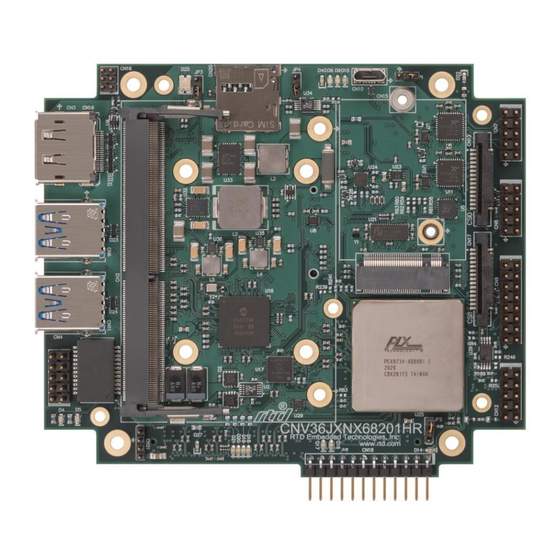
(CN1 Bottom) Auxiliary Power Figure 5 CNV36JXNX cpu/gpuModule (top view) Note Pin 1 of each connector is indicated by a white silk-screened square on the top side of the board and a square solder pad on the bottom side of the board. - Page 24 M.2 E-key slot Micro SD card (CN14) (CN9) PCIe/104 Bus (CN1) Figure 6 CNV36JXNX cpu/gpuModule (bottom view) CNV36JXNX User’s Manual BDM-610000090 Rev A...
- Page 25 Table 5 CNV36JXNX Basic Connectors Connector Function Size and Pitch Mating Connector PCIe/104 Type 2 Bus 156-pin, Samtec ASP-129637-03 (Bottom) 0.635mm Auxiliary Power 1x12, 0.1” FCI 65039-025LF (housing model number only) DisplayPort Molex P/N Series Molex P/N Series 68783- 47272-xxxx xxxx 2x5, 0.1”...
-
Page 26: Auxiliary Power (Cn3)
These devices include hard drive, front-end boards for data acquisition systems, and other devices. Power can also be conveyed to the module through the Auxiliary Power connector (CN3). The CNV36JXNX cpu/gpuModule requires +5 V and ground for operation. Note Although it is possible to power the cpu/gpuModule through the Auxiliary Power connector, the preferred method is to power it through the bus connector from a power supply in the stack. - Page 27 WARNING The user is responsible for any over-voltage and reverse voltage protection that would be necessary to power through CN3. Over-voltage damage at CN3 is not covered under warranty. Pin 1 Figure 7 Power Connector (CN3) CNV36JXNX User’s Manual BDM-610000090 Rev A...
-
Page 28: Utility Port 2.0 Connector (Cn5)
Shield Ground WARNING The pinout of the Utility Port 2.0 connector is not compatible with some older generations of RTD cpuModules. Attaching a legacy Utility Port harness to the Utility Port 2.0 connector may damage or destroy the cpu/gpuModule. Facing the connector pins, the pinout is: (pin one is indicated by a square solder pad and white silk screen) -
Page 29: Usb 2.0 Connection
(RTC). Connecting a battery is only required to maintain time when power is completely removed from the cpu/gpuModule. A battery is not required for board operation. CNV36JXNX User’s Manual BDM-610000090 Rev A... -
Page 30: Displayport Connector (Cn4)
DisplayPort Connector (CN4) The DisplayPort connector on the CNV36JXNX cpu/gpuModule is a standard PC DisplayPort connector completed with latch holes to provide a rugged connecting solution for latching DisplayPort cables. The DisplayPort supports all mandatory features of the VESA DisplayPort (DP) 1.4 standard and supports audio over the connection. - Page 31 Facing the connector pins of the DisplayPort connector (CN4), the pinout is: Figure 9 DisplayPort Connector CN4 AUX- AUX+ CFG1 LN2- LN2+ LN0- LN0+ LN3+ CFG2 LN3- LN1- LN1+ CNV36JXNX User’s Manual BDM-610000090 Rev A...
-
Page 32: Serial Port 1 (Cn7) And Serial Port 2 (Cn8)
Serial Port in RS-232 Mode Signal Function In/Out DB-25 DB-9 Receive Data Request To Send Transmit Data Clear To Send — Signal Ground — — — Signal Ground Facing the serial port’s connector pins, the pinout is: CNV36JXNX User’s Manual BDM-610000090 Rev A... -
Page 33: Rs-422 Or Rs-485 Serial Port
Facing the serial port connector, the pinout is: RXD- RXD+ TXD+ TXD- Rsvd Rsvd Rsvd Rsvd WARNING The pinout of the COM ports in RS-422 mode is not compatible with some older generations of RTD cpuModules. CNV36JXNX User’s Manual BDM-610000090 Rev A... - Page 34 Rsvd WARNING The pinout of the COM ports in RS-422 mode is not compatible with some older generations of RTD cpuModules. Note When using the serial port in RS-485 mode, the serial transmitters are enabled and disabled under software control. The transmitters can be enabled by manipulating the Request To Send (RTS*) signal of the serial port controller.
-
Page 35: Can Bus
You may use cvn36jxnx_serial.sh setup shell script to configure the CN7 for CAN Bus. The CAN transceiver on the CNV36JXNX can support data rates up to 5 Mbps. Table 13 provides the CN7 connector pinout when CAN Bus is enabled... -
Page 36: Digital I/O Port (Cn6)
44 for information on programming the DIO. Table 15 DIO Pinout (CN6) CN6 Pin Function CN6 Pin Function I/0-00 I/0-01 I/0-02 I/0-03 I/0-04 I/0-05 I/0-06 I/0-07 I/0-12 I/0-13 I/0-08 I/0-09 I0-10 I/0-11 +5 V CNV36JXNX User’s Manual BDM-610000090 Rev A... -
Page 37: Ethernet (10/100/1000Base-T And -Tx) Connector (Cn20)
10-Pin DIL Signal Function B+ (RX+) Receive+ (10/100) B- (RX–) Receive– (10/100) A+ (TX+) Transmit+ (10/100) A- (TX–) Transmit– (10/100) — AGND Ethernet Ground — AGND Ethernet Ground AGND AGND D– A– C– B– CNV36JXNX User’s Manual BDM-610000090 Rev A... -
Page 38: Mipi Csi-2 Camera Connectors (Cn13, Cn23)
MIPI CSI-2 Camera Connector Pinout Name Description Ground Data lane 0 Ground Data lane 1 Ground CLK- Clock CLK+ Ground PWDN Power Down MCLK Master Clock C interface for control 3.3V 3.3V power for camera CNV36JXNX User’s Manual BDM-610000090 Rev A... -
Page 39: Pcie/104 Type 2 Bus (Cn1 - Bottom)
PEx1_1Tp PEx1_0Tp PEx1_1Tn PEx1_0Tn PEx1_2Tp PEx1_3Tp PEx1_2Tn PEx1_3Tn PEx1_1Rp PEx1_0Rp PEx1_1Rn PEx1_0Rn PEx1_2Rp PEx1_3Rp PEx1_2Rn PEx1_3Rn PEx1_1Clkp PEx1_0Clkp PEx1_1Clkn PEx1_0Clkn +5V_STBY +5V_STBY PEx1_2Clkp PEx1_3Clkp PEx1_2Clkn PEx1_3Clkn CPU_DIR PWRGOOD Reserved Reserved Reserved Reserved Reserved PSON# CNV36JXNX User’s Manual BDM-610000090 Rev A... - Page 40 PEx4_1T(0)N PEx4_0T(0)N PEx4_1T(1)P PEx4_0T(1)P PEx4_1T(1)N PEx4_0T(1)N PEx4_1T(2)P PEx4_0T(2)P PEx4_1T(2)N PEx4_0T(2)N PEx4_1T(3)P PEx4_0T(3)P PEx4_1T(3)N PEx4_0T(3)N NC (SATA_T1_P) NC (SATA_T0_P) NC (SATA_T1_N) NC (SATA_T0_N) USB3_T1_P USB3_T0_P USB3_T1_N USB3_T0_N Reserved Reserved Reserved Reserved Reserved Reserved Reserved Reserved CNV36JXNX User’s Manual BDM-610000090 Rev A...
- Page 41 Reserved Reserved Reserved 1. Signals marked with (#) are active low. 2. +3.3V is not required for board operation. 12V Blade 5V Blade 5V Blade Figure 10 Locations of 5V and 12V Power Blades CNV36JXNX User’s Manual BDM-610000090 Rev A...
-
Page 42: Pcie/104 Type 2 Compatibility
This cpu/gpuModule supports a total of four PCIe x1 links and two PCIe x4 links for system expansion. The PCIe links are routed to CN1 Reserved (CN16 and CN12) CN16 is reserved for factory use and should be left unconnected. CN12 is the fan connector and is for factory use only. CNV36JXNX User’s Manual BDM-610000090 Rev A... -
Page 43: Chapter 4 Using The Cpu/Gpumodule
This chapter provides information for users who wish to develop their own applications programs for the CNV36JXNX cpu/gpuModule. This chapter includes information on the following topics: Operating System Specific Usage – page 44 Digital I/O – page 44 Power Management – page 45 Thermal Management – page 46 CNV36JXNX User’s Manual BDM-610000090 Rev A... -
Page 44: Operating System Specific Usage
Linux for Tegra kernel version 4.9. Earlier versions of the kernel CNV36JXNX may not contain drivers for all devices and may not work as expected. At the time of publication, RTD has validated Linux for Tegra 4.9. for NVIDIA® Jetson™ Linux Driver https://developer.nvidia.com/embedded/jetson-linux-r341 Package. -
Page 45: Power Management
USB device, such as mouse. AT vs. ATX Power Supplies Both AT and ATX power supplies may be used with the CNV36JXNX cpu/gpuModule, however AT power supplies do not provide any standby power to the cpu/gpuModule. -
Page 46: Thermal Management
RTD active solution using an environmental chamber. RTD evaluated the functionality of the NX module by running Jetson Benchmarks provided by NVIDIA. All parts, on the CNV36JXNX carrier module, are rated for -40℃ to +85℃ temperature range. It is important to note that the NVIDIA Jetson module has its own temperature ratings separate from the RTD carrier. -
Page 47: Appendix A Hardware Reference
Appendix A Hardware Reference This appendix provides information on CNV36JXNX cpu/gpuModule hardware, including: Jumper Settings and Locations – page 48 Onboard PCI/PCIe Devices – page 49 Physical Dimensions – page 50 Heatsink Dimensions – page 51 Flat-Heat Spreader Dimensions – page 51 CNV36JXNX User’s Manual... -
Page 48: Jumper Settings And Locations
JP followed by a number. Figure 11 shows the jumper locations that are used to configure the cpu/gpuModule. Table 20 lists the jumpers and their settings. Figure 11 CNV36JXNX Jumper Locations (top side) Table 20 CNV36JXNX Jumpers Jumper Pins Function Default W_DISABLE1 signal of the M.2 sockets. -
Page 49: Onboard Pci/Pcie Devices
Onboard PCI/PCIe Devices The CNV36JXNX cpu/gpuModule has several onboard PCIe devices, they are listed in the table below. Table 21 Onboard PCI/PCIe Devices Device ID Vendor ID Description 8734 10B5 PEX 8-Port PCI Express Switch 1AD0 10DE NVIDIA Xavier NX This device will appear eight times in PCI configuration space. -
Page 50: Physical Dimensions
Physical Dimensions Figure 12 CNV36JXNX Physical Dimensions (±0.005 inches) CNV36JXNX User’s Manual BDM-610000090 Rev A... -
Page 51: Heatsink Dimensions
Figure 13 CNV36JXNXD Heatsink with Height from Board Flat-Heat Spreader Dimensions For cooling solutions where it is desirable to mount the cpu/gpuModule to a flat surface, the CNV36JXNX may be ordered with a flat heat spreader instead of the standard passive heatsink. Each flat heat spreader has ten mounting locations which use 6-32 UNC x 0.138”... - Page 52 Figure 15 Flat Heat Spreader Hole Placement Figure 16 Flat Heat Spreader Height from Board CNV36JXNX User’s Manual BDM-610000090 Rev A...
-
Page 53: Appendix B Troubleshooting
Appendix B Troubleshooting Many problems you may encounter with operation of your CNV36JXNX cpu/gpuModule are due to common errors. This appendix includes the following sections to help you get your system operating properly. Common Problems and Solutions – page 54 Troubleshooting a PC/104 System –... -
Page 54: Common Problems And Solutions
Common Problems and Solutions Table 21 lists some of the common problems you may encounter while using your CNV36JXNX cpu/gpuModule and suggests possible solutions. If you are having problems with your cpu/gpuModule, review this table before contacting RTD Technical Support. -
Page 55: Troubleshooting A Pc/104 System
Troubleshooting a PC/104 System If you have reviewed the preceding table and still cannot isolate the problem with your CNV36JXNX cpu/gpuModule, please try the following troubleshooting steps. Even if the resulting information does not help you find the problem, it will be very helpful if you need to contact technical support. -
Page 56: Appendix Cidan™ Dimensions And Pinout
IDAN frame and all I/O connections are brought to the walls of each frame using standard PC connectors. On the CNV36JXNX, no connections are made from module to module internal to the system other than through the PCIe/104 Type 2 bus, enabling quick interchangeability and system expansion without hours of rewiring and board redesign. -
Page 57: Idan Contents
The IDAN-CNV36JXNX contains both a CNV36JXNX cpu/gpuModule and an ATX3510HR-190W power supply. Also, inside the IDAN-CNV36JXNX unit is a CMOS battery which is connected to the battery input connection of the cpu/gpuModule’s Utility Port 2.0 connector. The frame of the IDAN-CNV36JXNX brings out the cpu/gpuModule’s multi-color LED as well as the cpu/gpuModule’s reset button. -
Page 58: Idan Connectors
IDAN Connectors The figures below show the connector locations for the CNV36JXNX as they are brought out on the front and back panels of the IDAN-CNV36JXNX. For a full description of each connector on the CNV36JXNX, refer to Connecting to the Stack page 21. - Page 59 Table 23 IDAN- CNV36JXNX Connectors Board Function Connector IDAN Panel Mating Designator Description Connector Connector CN3, CN18 DisplayPort DisplayPort Molex 47272 Molex 68783 series (female) series CN12 USB Port USB Type A Samtec USB Type A Plug USBR-A-S- Receptacle (Utility Port 2.0)
-
Page 60: External I/O Connections
COM1/COM2 9-Pin D Connector (male) CPU Pin IDAN Single Single Single RS-232 RS-422 RS-485 (DB-9) — TXD– D– — — — TXD+ — — — RXD+ — — — — RXD– — — — CNV36JXNX User’s Manual BDM-610000090 Rev A... - Page 61 IDAN DIO Port CPU Pin # Pin # (CN9) I/0-00 I/0-02 I/0-04 I/0-06 I/0-12 I/0-08 I/0-10 — — — — — I/0-01 I/0-03 I/0-05 I/0-07 I/0-13 I/0-09 I/0-11 +5 V — — — — CNV36JXNX User’s Manual BDM-610000090 Rev A...
- Page 62 Table 27 Ethernet RJ45 Connector T568A Color Code IDAN Pin # RJ-45 Pin Signal CPU Pin # A+ (TX+) A- (TX–) B+ (RX+) B- (RX–) Note 1: White stripe indicated in cell fill color. CNV36JXNX User’s Manual BDM-610000090 Rev A...
-
Page 63: Appendix D Additional Information
Appendix D Additional Information NVIDIA Driver Information: https://developer.nvidia.com/embedded/jetson-linux-r341 PC/104 Specifications A copy of the latest PC/104 specifications can be found on the webpage for the PC/104 Embedded Consortium: http://www.pc104.org CNV36JXNX User’s Manual BDM-610000090 Rev A... -
Page 64: Appendix E Limited Warranty
Under no circumstances will RTD Embedded Technologies be liable to the purchaser or any user for any damages, including any incidental or consequential damages, expenses, lost profits, lost savings, or other damages arising out of the use or inability to use the product. - Page 65 www.rtd.com...
Need help?
Do you have a question about the CNV36JXNX and is the answer not in the manual?
Questions and answers