Canon iR3245 Troubleshooting Manual
Hide thumbs
Also See for iR3245:
- Service manual (746 pages) ,
- Manual (634 pages) ,
- Network manual (288 pages)

Related Manuals for Canon iR3245


Summary of Contents for Canon iR3245
-
Page 1: Troubleshooting
Troubleshooting Troubleshooting Please read this guide before operating this product. After you nish reading this guide, store it in a safe place for future reference. - Page 3 Troubleshooting...
-
Page 4: Manuals For The Machine
Manuals for the Machine The manuals for this machine are divided as follows. Please refer to them for detailed information. The manuals supplied with optional equipment are included in the list below. Depending on the system configuration and product purchased, some manuals may not be needed. Guides with this symbol are printed manuals. - Page 5 • Instructions for Operating the Machine e-Manual - Before You Start - Help - Copy - Send/Fax - Mail Box - Print - Web Access - Network - Remote UI - MEAP/SSO - Security - Software To view the manual in PDF format, Adobe Reader/Adobe Acrobat Reader is required. If Adobe Reader/Adobe Acrobat Reader is not installed on your system, please download it from the Adobe Systems Incorporated website.
-
Page 6: How This Manual Is Organized
Relationship between Original Orientation and Preprinted Paper Output Chart, and index. Considerable effort has been made to ensure that this manual is free of inaccuracies and omissions. However, as we are constantly improving our products, if you need an exact specification, please contact Canon. -
Page 7: Table Of Contents
Contents Preface .................ix How To Use This Manual . - Page 8 Main Power and Control Panel Power ..........1-14 How to Turn ON the Main Power .
- Page 9 Contacting Your Local Authorized Canon Dealer ........
- Page 10 Index ................4-53 System Management of the iR3245/iR3235/iR3230/iR3225 ......4-57 Entering the System Management Mode .
-
Page 11: Preface
Preface Thank you for purchasing the Canon iR3245/iR3235/iR3230/iR3225. Please read this manual thoroughly before operating the machine to familiarize yourself with its capabilities, and to make the most of its many functions. After reading this manual, store it in a safe place for future reference. -
Page 12: Keys Used In This Manual
Screen shots of the touch panel display used in this manual are those taken when the optional Color Universal Send Kit has been activated, and the following optional equipment is attached to the iR3245: the Feeder (DADF-U1), Super G3 FAX Board, UFR II/PCL Printer Kit, Finisher-S1, Additional Finisher Tray-B1, and Cassette Feeding Unit-Y3. -
Page 13: Illustrations Used In This Manual
Illustrations Used in This Manual Illustrations used in this manual are those displayed when the iR3245 has the following optional equipment attached to it: the Feeder (DADF-U1), Finisher-S1, Additional Finisher Tray-B1, and Cassette Feeding Unit-Y3. Abbreviations Used in This Manual... -
Page 14: Trademarks
Trademarks MEAP and the MEAP logo are trademarks of Canon Inc. AppleTalk and Macintosh are trademarks of Apple Inc., registered in the U.S. and other countries. Windows, the Windows logo, Windows Vista, and the Windows Vista logo are trademarks or registered trademarks of Microsoft Corporation in the U.S. -
Page 15: Operations And Terms Used In This Manual
Operations and Terms Used in This Manual This machine makes effective use of memory to perform print operations efficiently. For example, as soon as the machine has scanned the original that you want to copy, it can immediately scan the next person's original. - Page 16 Copying Printing data scanned from an original, followed by finishing options, such as stapling.
-
Page 17: Legal Notices
Product Name Safety regulations require the product's name to be registered. In some regions where this product is sold, the following name(s) in ( ) may be registered instead. iR3245/iR3235/iR3230 (F152000) iR3225 (F152300) EMC Directive This equipment conforms with the essential requirements of EC Directive 89/336/EEC. We declare that this product conforms with the EMC requirements of EC Directive 89/336/EEC at nominal mains input 230V, 50Hz although the rated input of the product is 220V-240V, 50/60Hz. -
Page 18: Laser Safety
Laser Safety This product complies with 21 CFR Chapter 1 Subchapter J as a Class I laser product under the U.S. Department of Health and Human Services (DHHS) Radiation Performance Standard according to the Radiation Control for Health and Safety Act of 1968. Also, this product is certified as a Class I laser product under IEC60825-1: 2007 and EN60825-1: 2007. -
Page 19: International Energy Star Program
International Energy Star Program As an Partner, Canon Inc. has determined that this machine NERGY TAR® meets the Program guidelines for energy efficiency. NERGY TAR® The International Office Equipment Program is an NERGY TAR® international program that promotes energy saving through the use of computers and other office equipment. -
Page 20: Copyright
Canon’s licenser to you for any intellectual property of LICENSORS. You may use the SOFTWARE solely for use with the Canon product you purchased (the “PRODUCT”). You may not assign, sublicense, market, distribute, or transfer the SOFTWARE to any third party without prior written consent of Canon and LICENSORS. -
Page 21: The Software Subjected To The Other Conditions
Disclaimers The information in this document is subject to change without notice. CANON INC. MAKES NO WARRANTY OF ANY KIND WITH REGARD TO THIS MATERIAL, EITHER EXPRESS OR IMPLIED, EXCEPT AS PROVIDED HEREIN, INCLUDING WITHOUT LIMITATION, THEREOF, WARRANTIES AS TO MARKETABILITY, MERCHANTABILITY, FITNESS FOR A PARTICULAR PURPOSE OF USE OR NON-INFRINGEMENT. -
Page 22: Legal Limitations On The Usage Of Your Product And The Use Of Images
Legal Limitations on the Usage of Your Product and the Use of Images Using your product to scan, print or otherwise reproduce certain documents, and the use of such images as scanned, printed or otherwise reproduced by your product, may be prohibited by law and may result in criminal and/or civil liability. -
Page 23: Important Safety Instructions
If these items are dropped or spilled inside the machine, immediately turn OFF the main power switch, and disconnect the power cord from the power outlet. Then, contact your local authorized Canon dealer. Necklaces and other metal objects Cups, vases, flowerpots, and other containers filled with water or liquids... - Page 24 • Do not install the machine in unstable locations, such as unsteady platforms or inclined floors, or in locations subject to excessive vibrations, as this may cause the machine to fall or tip over, resulting in personal injury. • Never block the ventilation slots and louvers on the machine. These openings are provided for proper ventilation of working parts inside the machine.
-
Page 25: Power Supply
Power Supply • Do not damage or modify the power cord. Also, do not place heavy objects on the power cord, or pull on or excessively bend it, as this could cause electrical damage and result in a fire or electrical shock. -
Page 26: Handling
If the machine makes strange noises, or gives off smoke, heat, or strange smells, immediately turn OFF the main power switch, and disconnect the power cord from the power outlet. Then, contact your local authorized Canon dealer. Continued use of the machine in this condition may result in a fire or electrical shock. - Page 27 • Do not place your hands, hair, clothing, etc., near the exit and feed rollers. Even if the machine is not in operation, your hands, hair, or clothing may get caught in the rollers, which may result in personal injury or damage if the machine suddenly starts printing. •...
-
Page 28: Maintenance And Inspections
Maintenance and Inspections • When cleaning the machine, first turn OFF the main power switch, then disconnect the power cord. Failure to observe these steps may result in a fire or electrical shock. • Disconnect the power cord from the power outlet regularly, and clean the area around the base of the power plug's metal pins and the power outlet with a dry cloth to ensure that all dust and grime is removed. -
Page 29: Consumables
• When loading paper or removing jammed originals or paper, take care not to cut your hands on the edges of the originals or paper. • When removing a used toner cartridge, remove the cartridge carefully to prevent the toner from scattering and getting into your eyes or mouth. -
Page 30: Super G3
Super G3 Super G3 is a phrase used to describe the new generation of fax machines that use ITU-T V.34 standard 33.6 Kbps* modems. Super G3 High Speed Fax machines allow transmission times of approximately 3 seconds* per page which results in reduced telephone line charges. -
Page 31: Periodic Inspection Of The Breaker
Make sure that the main power is turned OFF, before inspecting the breaker. • If a malfunction occurs after an inspection, contact your local authorized Canon dealer. Checking the Breaker Push the test button on the rear of the machine with the tip of a ball-point pen, or a similar object. - Page 32 If the breaker lever does not switch to the OFF (" " side) position, despite carrying out the above procedure two or three times, contact your local authorized Canon dealer. Switch the breaker lever to ON ("I" side). ( side)
- Page 33 Press the main power switch to the "I" side. ( I side) ( side) Fill in the check sheet, located on the next page, to document your periodic inspections of the breaker. xxxi...
-
Page 34: Check Sheet For The Periodic Inspection Of The Breaker
Fill in the date of inspection and the name of the inspector. When the inspection is completed successfully, write a check mark under "OK." If not, contact your local authorized Canon dealer. (Also, write a check mark under "NG" (No Good).) Result... - Page 35 Before You Start Using This Machine This chapter describes what you should know before using the machine. Installation Location and Handling ............... . . 1-2 Installation Precautions .
-
Page 36: Installation Location And Handling
Installation Location and Handling This section describes precautions for installation location and handling. We recommend that you read this section prior to using this machine. Installation Precautions Avoid Installing the Machine in the Following Locations Avoid locations subject to temperature and humidity extremes, whether low or high. - Page 37 Avoid poorly ventilated locations. This machine generates a slight amount of ozone during normal use. Although sensitivity to ozone may vary, this amount is not harmful. Ozone may be more noticeable during extended use or long production runs, especially in poorly ventilated rooms. It is recommended that the room be appropriately ventilated, sufficient to maintain a comfortable working environment, in areas of machine operation.
- Page 38 Avoid locations that are subject to vibration. For example, avoid installing the machine on unstable floors or stands. Avoid exposing the machine to rapid changes in temperature. If the room in which the machine is installed is cold but rapidly heated, water droplets (condensation) may form inside the machine.
-
Page 39: Select A Safe Power Supply
Do not remove the machine's leveling feet. Do not remove the machine's leveling feet after the machine has been installed. If you put weight on the front of the machine while the drawers or units within the machine are pulled out, the machine may fall forward. To prevent this from happening, make sure that the machine's leveling feet are in place. -
Page 40: Moving The Machine
Moving the Machine If you intend to move the machine, even to a location on the same floor of your building, contact your local authorized Canon dealer beforehand. Do not attempt to move the machine yourself. Handling Precautions Do not attempt to disassemble or modify the machine. - Page 41 OFF, disconnect the power cord from the outlet, and call your local authorized Canon dealer. Using the machine in this state may cause a fire or electrical shock. Also, avoid placing objects around the power plug so that the machine can be disconnected whenever necessary.
- Page 42 Do not turn the main power switch OFF or open the front covers while the machine is in operation. This might result in paper jams. Do not use flammable sprays, such as spray glue, near the machine. There is a danger of ignition.
-
Page 43: Backing Up Data
Please regularly back up your important data, as it is possible that a malfunction in the hard disk may cause received data and stored data to be lost. Please note that Canon will not be held responsible for any damages caused by the loss of data. The data that can be backed up is indicated below. -
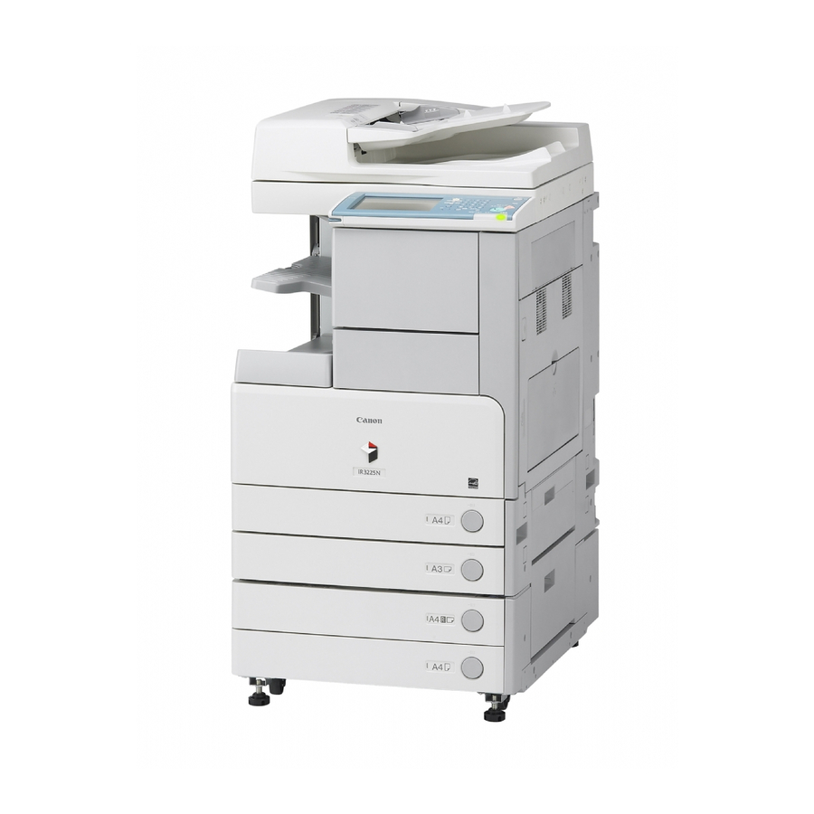
Page 44: Parts And Their Functions
Parts and Their Functions This section provides you with the names and functions of all the parts on the outside and inside of the main unit, control panel, and the touch panel display. An illustration of the machine with some optional equipment attached to it is also provided. - Page 45 Drawers 1 and 2. automatically turns over two-sided originals to make two Paper Drawer 2 or one sided copies. For the iR3245/iR3235, the Feeder (DADF-U1) is standard-equipped in some regions. Holds up to 550 sheets of paper (80 g/m Control Panel...
-
Page 46: Internal View
Internal View The optional Feeder (DADF-U1) and Cassette Feeding Unit-Y3 are attached. Platen Glass Toner Supply Port Cover Use the platen glass when scanning books, thick originals, Open this cover to replace the toner cartridge. thin originals, transparencies, etc. Toner Cartridge Fixing Unit's Upper Cover When toner runs out, pull out the toner cartridge, and Open this cover to clear a paper jam in the fixing unit. -
Page 47: Control Panel Parts And Functions
If you lose the edit pen, contact your local Flashes or blinks green when the machine is performing authorized Canon dealer. Do not use an object with a sharp operations, and maintains a steady green light when fax end on the control panel, such as a pencil or ballpoint pen, data is stored in memory. -
Page 48: Main Power And Control Panel Power
Main Power and Control Panel Power The machine is provided with two power switches, a main power switch and a control panel power switch, as well as a breaker that detects excess current or leakage current. How to Turn ON the Main Power This section explains how to turn ON the main power. - Page 49 If the main power indicator on the control panel does not light even though the main power switch is ON, be sure to check the breaker to see if it is OFF. (See “When the Power Does Not Turn ON, ” on p. 3-109.) The screens shown below are displayed while the system software is loading.
- Page 50 • Once the message <Reservation copies can be made.> appears on the touch panel display, you can specify settings, and copying or printing begins automatically as soon as the machine finishes warming up. (See e-Manual > Copy.) • In the case above, the standard settings are selected. •...
- Page 51 ☐ After the Start Up screen disappears, the MEAP Start Up screen is displayed. You can press [→] to switch to the Basic Features screen to use the Copy, Mail Box, etc. functions even if the MEAP Start Up screen is still displayed. ☐...
- Page 52 ☐ After the Start Up screen disappears, the MEAP Start Up screen is displayed regardless of the Set as Initial Function settings. • Do not turn the main power OFF, if you want to send or receive I-fax documents. Also, do not turn the main power OFF, if the optional Color Universal Send Kit is activated, or fax board is installed, and you want to be able to send or receive fax documents.
-
Page 53: Control Panel Power Switch
Control Panel Power Switch Press the control panel power switch to cancel the Sleep mode and resume normal machine operations. • The machine can receive and print documents from a personal computer when it is in the Sleep mode. I-fax and fax documents can also be received while the machine is in the Sleep mode. - Page 54 Do not initiate the Shutdown mode while fonts are being downloaded. • (Additional Functions) → You can also force the machine into the Shutdown mode by pressing [Common Settings] → [ Shutdown Mode]. • You cannot force the machine into the Shutdown mode in the following cases: When the machine is receiving and updating device information When the machine is browsing device information When the machine is importing or exporting data using the Remote UI function...
- Page 55 • Jobs that are displayed on the job confirmation screen are: Current copy, fax, and print jobs (including secured print jobs) Copy and print jobs (including secured print jobs) that are waiting to be processed • On the job confirmation screen, the current job is displayed on the first line, and the other jobs are processed in the order in which they were reserved (up to seven jobs).
- Page 56 Press [Yes]. However, as it is possible that this will destroy data which is being processed or cause damage to the machine, it is not recommended. Note that Canon will not be liable for any damages resulting from the loss of data on the hard disk drive. For more information, contact your local authorized Canon dealer.
- Page 57 After the machine shuts down, the control panel power switch automatically turns OFF and the main power switch of machine automatically switches to the " " side. The machine may continue to operate during or after the shutdown process. Do not unplug the power cord until the device sounds stop.
- Page 58 1-24 Main Power and Control Panel Power...
-
Page 59: Routine Maintenance
Routine Maintenance This chapter describes how to load paper, perform routine cleaning, and replace consumables. Paper Drawers................... . . 2-2 Loading Paper . -
Page 60: Paper Drawers
Paper Drawers This section describes how to load paper into the paper drawers. • The following paper sizes can be loaded into Paper Drawers 1, 2, 3, and 4. Paper Drawer 1: B4, A4, A4R, B5, B5R, A5R, and envelopes Paper Drawer 2, 3, 4: A3, B4, A4, A4R, B5, B5R, and A5R Envelopes can be loaded into Paper Drawer 1 only if the optional Envelope Feeder Attachment-C2 is attached. - Page 61 • A screen prompting you to load paper also appears if the selected paper drawer is not fully inserted into the machine. Make sure that the paper drawer is properly in place. • Do not load nonstandard paper sizes into the paper drawers. •...
- Page 62 Press and release the button on the paper drawer in which you want to load paper. Grip the handle, and pull out the paper drawer until it stops. Open a package of paper, and remove the paper stack. Paper Drawers...
- Page 63 Rewrap any remaining paper in its original package, and store it in a dry place, away from direct sunlight. • For high-quality printouts, use paper recommended by Canon. • Before loading paper, always fan the sheets several times, and align the edges to facilitate feeding.
- Page 64 • Paper which has been rolled or curled must be straightened out prior to use. • Make sure that the height of the paper stack does not exceed the loading limit mark ( ) at the back of the paper drawer. •...
-
Page 65: Adjusting A Paper Drawer To Hold A Different Paper Size
If paper runs out during copying or printing, load a new paper stack, and follow the instructions on the touch panel display. The machine automatically restarts, and produces the remaining copies or prints. Adjusting a Paper Drawer to Hold a Different Paper Size If you want to load a different paper size into a paper drawer, follow the procedure described below to adjust the paper drawer guides. - Page 66 Lift out the left guide, and insert it into the holes marked for the desired paper size. Left Guide Squeeze the lever on the front guide, as shown below. Without releasing the lever, slide the front guide to align it with the mark for the desired paper size.
- Page 67 Turn the paper size dial on the right side of the paper drawer, so that the arrow points to the paper size being loaded. Paper Size Dial Arrow If the paper size dial is not positioned correctly to the paper size loaded in the paper drawer, the wrong paper size will be shown on the touch panel display.
-
Page 68: Paper Deck-Q1 (Optional)
Paper Deck-Q1 (Optional) If you attach the optional Paper Deck-Q1 to the machine, you have one additional source of paper for printing jobs. The Paper Deck-Q1 holds up to 2,700 sheets of paper (80 g/m If the machine is in the Sleep mode (the touch panel is not displayed, and only the main power indicator is lit), you may not be able to open the paper deck. - Page 69 If a message prompting you to load paper appears during printing, the remaining prints are automatically made after you load the correct paper. If you select another paper source, the remaining prints are made after you press [OK]. Press the open button to open the paper deck. The inside lifter automatically descends to the paper loading position.
- Page 70 Paper which has been printed on using a thermal transfer printer (Do not print on the reverse side of this paper either.) • For high-quality printouts, use paper recommended by Canon. • Before loading paper, always fan the sheets several times, and align the edges to facilitate feeding.
- Page 71 • Paper which has been rolled or curled must be straightened out before loading it into the paper deck. • Make sure that the height of the paper stack does not exceed the loading limit mark ( ) on the inside of the paper deck.
-
Page 72: Envelope Feeder Attachment-C2 (Optional)
Envelope Feeder Attachment-C2 (Optional) This section explains how to use the optional Envelope Feeder Attachment-C2. The optional Envelope Feeder Attachment-C2 can only be attached to Paper Drawer 1. How to Use the Envelope Feeder Attachment The following six types of envelopes can be loaded into the envelope feeder attachment: COM10 No.10, Monarch: Catalog Glove No.8, DL, ISO-B5, ISO-C5, and Yougata 4. - Page 73 - Monarch: Catalog Glove No.8: Mailwell No.553 - DL: Mailwell/Schneidersone No.11345 - Yougata 4: Uzumaki Y-401 • If you want to adjust the width guides to load ISO-C5 or ISO-B5 envelopes, contact your local authorized Canon dealer. Envelope Feeder Attachment-C2 (Optional) 2-15...
-
Page 74: Preparing The Envelopes
• For more information on using envelopes other than COM10 No.10, see “Changing Envelope Sizes, ” on p. 2-21. • For more information on envelope types that can be loaded in the envelope feeder attachment, see e-Manual > Basic Operations. Preparing the Envelopes This section explains how to prepare the envelopes before loading them into the paper drawer. - Page 75 Place the envelopes on a clean, level surface, and press all the way around the envelopes by hand, in the direction of the arrows, to remove any curls. Repeat this step five times for each set of five envelopes. If you are using ISO-B5, ISO-C5, COM10 No.10, Monarch: Catalog Glove No.8, or DL envelopes, hold down the four corners of the envelopes firmly, so that they and the sealed or glued portion stay flat.
-
Page 76: Loading Envelopes
• If you use envelopes that have glue attached to their flaps, the glue may melt due to the heat and pressure of the fixing unit. • Take particular care to spread the envelopes out in the direction that they will be fed. •... - Page 77 Grip the handle, and pull out the paper drawer until it stops. Load 10 envelopes at a time with the side you want to print on face up. While loading the envelopes, press down on the right side of the receptacle to lock them into place.
- Page 78 Align the leading edges of the envelopes, and make sure that they are held in place under the claw. • Envelopes which have been rolled or curled must be straightened out prior to use. • Make sure that the height of the envelope stack does not fall below the height limit mark ( •...
-
Page 79: Changing Envelope Sizes
Never place paper or any other items in the empty part of the paper drawer next to the envelopes. Doing so may cause paper jams. If output has been stopped due to an insufficient number of envelopes, load more envelopes, and follow the instructions on the touch panel display. - Page 80 Pull and lift the paper drawer out of the machine by holding its left and right sides with both hands. Remove all of the envelopes that are loaded in the paper drawer (several envelopes at a time). 2-22 Envelope Feeder Attachment-C2 (Optional)
- Page 81 Remove the left guide of the envelope feeder attachment, and insert the left guide into the appropriate slot for the desired envelope size. To remove the left guide, tilt the left guide to the right, and then pull it up. Left Guide Loosen the two screws fixing the front width guide of the envelope feeder attachment.
- Page 82 Fix the front width guide in place with the screws. Move the back width guide of the envelope feeder attachment in accordance with steps 6 to 8. Load 10 envelopes at a time with the side you want to print on face up. While loading the envelopes, press down on the right side of the receptacle to lock them into place.
- Page 83 Load the envelopes, as shown below. Front Align the leading edges of the envelopes, and make sure that they are held in place under the claw. Claw • Envelopes which have been rolled or curled must be straightened out prior to use. •...
- Page 84 Turn the paper size dial on the right side of the paper drawer, so that the arrow points to 'ENV.' . Then, set the size switch to 'ENV.1' or 'ENV.2' . Arrow Paper Size Dial Size Switch [ENV.1] enables the envelope size and type stored in ENV.1 in Envelope Cassette in Common Settings (from the Additional Functions screen) to be loaded.
- Page 85 When returning the paper drawer to its original position, be careful not to get your fingers caught, as this may result in personal injury. Never place paper or any other items in the empty part of the paper drawer next to the envelopes. Doing so may cause paper jams.
-
Page 86: Feeder (Dadf-U1) (Optional)
• In some regions, the Feeder (DADF-U1) may be standard-equipped for the iR3245/iR3235. Replacing the Stamp Cartridge Open the feeder cover, and then open the inner cover. - Page 87 Push in the new stamp cartridge until it clicks, using tweezers. • Make sure that the stamp cartridge is not protruding from the surface. • Insert the stamp cartridge properly, or paper jams may occur. Gently close the inner cover, and then close the feeder cover. When closing the covers, be careful not to get your fingers caught, as this may result in personal injury.
-
Page 88: Finisher-S1/Puncher Unit-Q1/R1/S1 (Optional)
Follow the procedure described below to replace the staple cartridge. Use only staple cartridges intended for use with this machine. We recommend that you order staple cartridges from your local authorized Canon dealer before your stock runs out. 2-30... - Page 89 Open the front cover of the finisher. Lift the handle of the finisher unit up, and then pull it out to the left. Do not place any objects on the finisher unit, or lean on it, as doing so may damage the machine, or cause the machine to fall over, resulting in personal injury.
- Page 90 Lift and pull out the staple case from the stapler unit, holding it by the green tab. Place the staple case, as shown below, press the area indicated by PUSH, and then pull out the staple cartridge. Insert the new staple cartridge. Press the spring-loaded case down until it clicks into place.
- Page 91 • Use only staple cartridges intended for use with this machine. • Do not remove the seal that holds the staples together before you place the staple cartridge into the staple case. Only one staple cartridge can be inserted at a time. Remove the seal holding the staples together, by pulling it straight out, and then down.
- Page 92 Lift the handle of the finisher unit up, and then return the finisher unit to its original position. When returning the finisher unit to its original position, do not place your fingers or hands under the finisher, as they may get caught, resulting in personal injury. Close the front cover of the finisher.
-
Page 93: Removing Punch Waste
Removing Punch Waste When the punch waste tray of the optional Puncher Unit-Q1/R1/S1 becomes full, a screen similar to the one shown below appears on the touch panel display. Follow the procedure described below to remove the punch waste. This procedure is necessary only if the optional Puncher Unit-Q1/R1/S1 is attached. Open the front cover of the finisher. - Page 94 Pull out the punch waste tray. Discard the punch waste. Make sure that the punch waste tray is completely emptied. 2-36 Finisher-S1/Puncher Unit-Q1/R1/S1 (Optional)
- Page 95 Return the punch waste tray to its original position. If the punch waste tray is not securely in place, you cannot make prints in the Hole Punch mode. Close the front cover of the finisher. When closing the front cover of the finisher, be careful not to get your fingers caught, as this may result in personal injury.
-
Page 96: Finisher-Ae1/Saddle Finisher-Ae2/Puncher Unit-L1/M1/N1 (Optional)
Follow the procedure described below to replace the staple cartridge. Use only staple cartridges intended for use with this machine. We recommend that you order staple cartridges from your local authorized Canon dealer before your stock runs out. - Page 97 Open the front cover of the finisher. The Optional Saddle Finisher-AE2 The Optional Finisher-AE1 Lift and pull out the staple case from the stapler unit, holding it by the green tab. Finisher-AE1/Saddle Finisher-AE2/Puncher Unit-L1/M1/N1 (Optional) 2-39...
- Page 98 Place the staple case, as shown below, press the area indicated by PUSH, and then pull out the staple cartridge. Insert the new staple cartridge. Press the spring-loaded case down until it clicks into place. • Use only staple cartridges intended for use with this machine. •...
- Page 99 Remove the seal holding the staples together, by pulling it straight out, and then down. Make sure that you pull the seal straight out, and then down. If you pull it out at an angle, it may tear. Gently push the staple case into the stapler unit, until it is securely in place. Finisher-AE1/Saddle Finisher-AE2/Puncher Unit-L1/M1/N1 (Optional) 2-41...
-
Page 100: Replacing The Staple Cartridge In The Saddle Stitcher Unit
Close the front cover of the finisher. The Optional Saddle Finisher-AE2 The Optional Finisher-AE1 When closing the front cover of the finisher, be careful not to get your fingers caught, as this may result in personal injury. If there are no staples ready for stapling after the cover is closed, the stapler unit automatically performs a "dry"... - Page 101 • This procedure is necessary only if the optional Saddle Finisher-AE2 is attached. • We recommend that you order staple cartridges from your local authorized Canon dealer before your stock runs out. Open the front cover of the finisher. Grip the saddle stitcher unit by its handle, and pull it out of the finisher until it stops.
- Page 102 Pull the stapler unit of the saddle stitcher unit towards you, and then push it up. Stapler Unit of the Saddle Stitcher Unit Pull out the empty staple cartridge, holding it by its left and right sides. Insert the new staple cartridge. Only one staple cartridge can be inserted at a time.
- Page 103 Pull the stapler unit of the saddle stitcher unit towards you, and then push it down into its original position. Gently push the saddle stitcher unit back into its original position. Close the front cover of the finisher. Finisher-AE1/Saddle Finisher-AE2/Puncher Unit-L1/M1/N1 (Optional) 2-45...
-
Page 104: Removing Punch Waste
When closing the front cover of the finisher, be careful not to get your fingers caught, as this may result in personal injury. When you have replaced the staple cartridge, be sure to manually reposition the staples in the saddle stitcher unit. - Page 105 Open the front cover of the punch waste tray. Pull out the punch waste tray. Discard the punch waste. Make sure that the punch waste tray is completely emptied. Finisher-AE1/Saddle Finisher-AE2/Puncher Unit-L1/M1/N1 (Optional) 2-47...
- Page 106 Return the punch waste tray to its original position. If the punch waste tray is not securely in place, you cannot make prints in the Hole Punch mode. Close the front cover of the punch waste tray. When closing the front cover of the punch waste tray, be careful not to get your fingers caught, as this may result in personal injury.
-
Page 107: Replacing The Toner Cartridge
Replacing the Toner Cartridge When there is only a small amount of toner remaining inside the machine, the following message appears on the touch panel display. You can continue printing, but at this time you should purchase a new toner cartridge to have it available when needed. When toner runs out completely and prints can no longer be made, a screen with instructions on how to replace the toner cartridge, like the one shown below, appears on the touch panel display. - Page 108 Do not burn or throw used toner cartridges into open flames, as this may cause the toner remaining inside the cartridges to ignite, resulting in burns or a fire. • Keep toner out of the reach of small children. If toner is ingested, consult a physician immediately. •...
- Page 109 Lift up the locking lever until it becomes vertical. Make sure that the (down arrow) on the locking lever is aligned with the (up arrow) of the (Unlock) icon position before proceeding. Pull the toner cartridge out of the toner supply port. Pull the toner cartridge out halfway, and then remove it completely while supporting it and keeping it straight with your other hand from underneath.
- Page 110 Twist the red protective cap of the new toner cartridge in the direction of the arrow (counterclockwise) to remove it. Do not touch the tip of the toner cartridge or subject it to shock by hitting it. Doing so may cause the toner cartridge to leak.
- Page 111 Push the locking lever down into its original position. Make sure that the (down arrow) on the locking lever is aligned with the (right arrow) of the (Lock) icon position. If you insert a toner cartridge intended for use in a different machine, the locking lever will not move. Close the toner supply port cover.
-
Page 112: Routine Cleaning
Routine Cleaning If the original is not copied clearly, clean the following parts of the machine. For high-quality printouts, we recommend cleaning these parts once or twice a month. • Platen glass • Underside of the platen cover • Feeder's rollers •... -
Page 113: Platen Glass And Cover
Platen Glass and Cover Clean the platen glass and the underside of the optional platen cover by following the procedure below. If the platen glass or the underside of the optional platen cover is dirty, the original may not be scanned clearly, or the size of the original may be detected incorrectly. -
Page 114: Manual Feeder Cleaning
Manual Feeder Cleaning If originals that have been fed through the feeder have streaks or appear dirty, clean the feeder's rollers. Do not dampen the cloth too much, as this may damage the original or break the machine. • Spin the rollers while cleaning them. •... - Page 115 Open the inner cover, holding it by its front tab. Inner Cover Clean the rollers (a total of three places) inside the inner cover with a cloth dampened with water. Then, wipe the area with a soft, dry cloth. Clean the transparent plastic part of the inner cover with a cloth dampened with water.
- Page 116 Close the inner cover. When closing the inner cover, be careful not to get your fingers caught, as this may result in personal injury. Close the feeder cover. When closing the feeder cover, be careful not to get your fingers caught, as this may result in personal injury.
- Page 117 Lift the feeder. Clean the feeder scanning area with a cloth dampened with water. Then, wipe the area with a soft, dry cloth. Feeder's Scanning Area While turning the resin roller, clean the resing roller and the area around the resin roller with a cloth dampened with water. Then, wipe the area with a soft, dry cloth.
- Page 118 Close the feeder. • When closing the feeder, be careful not to get your fingers caught, as this may result in personal injury. • Be aware that the light emitted from the platen glass may be very bright when closing the feeder.
-
Page 119: Automatic Feeder Cleaning
Automatic Feeder Cleaning If your originals have black streaks or appear dirty after scanning them through the feeder, clean the rollers of the feeder. This procedure is necessary only if the optional Feeder (DADF-U1) is attached. It takes approximately 20 seconds to clean the feeder. (Additional Functions) →... -
Page 120: Consumables
To prevent moisture build-up, tightly wrap any remaining paper in its original package for storage. • For high-quality printouts, use paper recommended by Canon. • Some commercially available paper types are not suited for this machine. Contact your local authorized Canon dealer when you need to purchase paper. 2-62 Consumables... - Page 121 Toner If a message prompting you to replace the toner cartridge appears on the touch panel display, replace the used toner cartridge with a new one. Use only toner cartridges intended for use with this machine. • Do not burn or throw used toner cartridges into open flames, as this may cause the toner remaining inside the cartridges to ignite, resulting in burns or a fire.
- Page 122 2-64 Consumables...
- Page 123 Contacting Your Local Authorized Canon Dealer ........
-
Page 124: Reducing The Frequency Of Paper Jams
Reducing the Frequency of Paper Jams If paper jams occur frequently, even though there is no apparent problem with the machine, either one of the following two reasons may be the cause. Follow the instructions described below to reduce the frequency of paper jams. There are torn pieces of paper left inside the machine. -
Page 125: Clearing Paper Jams
Clearing Paper Jams If a paper jam occurs, the following screens appear on the touch panel display. Screens Indicating the Locations of Paper Jams The screen indicating the location of the paper jam and instructions on how to clear the paper jam appear on the touch panel display. - Page 126 When removing paper which has become jammed inside the machine, take care not to cut your hands or injure yourself on the inside of the machine. If you cannot remove the paper, contact your local authorized Canon dealer. • When removing paper which has become jammed inside the machine, take care not to allow the toner on the jammed paper to come into contact with your hands or clothing, as this will dirty your hands or clothing.
- Page 127 If paper is jammed in several locations, remove the jammed paper in the order indicated on the touch panel display. Inspect all paper jam locations indicated on the touch panel display, and remove any jammed paper. See the appropriate pages below for instructions on finding and removing jammed paper. Or, you can follow the instructions on the touch panel display.
- Page 128 If a paper jam occurs inside an optional unit, see the instructions on the following pages. Cassette Feeding Unit-Y3 ☐ See “Cassette Feeding Unit-Y3 (Optional), ” on p. 3-29. Paper Deck-Q1 ☐ See “Paper Deck-Q1 (Optional), ” on p. 3-33. Clearing Paper Jams...
- Page 129 Feeder (DADF-U1) ☐ See “Feeder (DADF-U1) (Optional), ” on p. 3-37. Finisher-S1 ☐ See “Finisher-S1 (Optional), ” on p. 3-41. ☐ See “Finisher-S1/Puncher Unit-Q1/R1/S1 (Optional), ” on p. 3-47. ☐ See “Inside the Transfer Cover of the Finisher-S1 (Optional), ” on p. 3-54. Inner 2 Way Tray-D1 ☐...
- Page 130 Copy Tray-J1 ☐ See “Copy Tray-J1 (Optional), ” on p. 3-77. Finisher-AE1 ☐ See “Inside the Top Cover of the Finisher-AE1/Saddle Finisher-AE2 (Optional), ” on p. 3-58. ☐ See “Inside the Buffer Pass Unit-E2 of the Finisher-AE1/Saddle Finisher-AE2 (Optional), ” on p. 3-61. Clearing Paper Jams...
- Page 131 Saddle Finisher-AE2 ☐ See “Inside the Top Cover of the Finisher-AE1/Saddle Finisher-AE2 (Optional), ” on p. 3-58. ☐ See “Inside the Buffer Pass Unit-E2 of the Finisher-AE1/Saddle Finisher-AE2 (Optional), ” on p. 3-61. ☐ See “Inside the Front Cover of the Saddle Finisher-AE2 (Optional), ” on p. 3-63. ☐...
- Page 132 Puncher Unit-L1/M1/N1 ☐ See “Puncher Unit-L1/M1/N1 (Optional), ” on p. 3-70. After you have removed all of the jammed paper in the locations indicated on the touch panel display, restore all levers and covers to their original positions. Continue to follow the procedure and instructions on the touch panel display.
-
Page 133: Fixing Unit (Inside The Main Unit)
Fixing Unit (Inside the Main Unit) If a paper jam occurs in the fixing unit area, a screen similar to the one shown below appears on the touch panel display. Check the location of the paper jam, and follow the procedure described below, and the procedure that appears on the touch panel display, to remove the jammed paper. - Page 134 Press the button on the right cover of the main unit, and open the right cover. If the optional Paper Deck-Q1 is attached to the main unit, move the paper deck away from the main unit before proceeding with this procedure. For more information, see e-Manual > Optional Equipment. If the optional Copy Tray-J1 is attached to the main unit, remove all of the output paper from the tray.
- Page 135 Remove any jammed paper protruding from the lower part of the fixing unit. Place your hand where the hand symbol ( ) is located on the right cover of the main unit, and then gently close the right cover until it clicks into place in the closed position.
-
Page 136: Duplexing Unit (Inside The Main Unit)
Follow the instructions on the touch panel display. The screen indicating the location of the paper jam repeatedly appears on the touch panel display until the paper jam is entirely cleared. For more information, see “Screens Indicating the Locations of Paper Jams, ” on p. - Page 137 Press the button on the right cover of the main unit, and open the right cover. If the optional Paper Deck-Q1 is attached to the main unit, move the paper deck away from the main unit before proceeding with this procedure. For more information, see e-Manual > Optional Equipment. If the optional Copy Tray-J1 is attached to the main unit, remove all of the output paper from the tray.
- Page 138 Place your hand where the hand symbol ( ) is located on the right cover of the main unit, and then gently close the right cover until it clicks into place in the closed position. If the optional Paper Deck-Q1 was moved away from the main unit, reconnect it to the main unit. For more information, see e-Manual >...
-
Page 139: Stack Bypass
Stack Bypass If a paper jam occurs inside the stack bypass, a screen similar to the one shown below appears on the touch panel display. Check the location of the paper jam, and follow the procedure described below, and the procedure that appears on the touch panel display, to remove the jammed paper. Remove all of the paper that is not jammed from the stack bypass. - Page 140 Remove any jammed paper. Press the button on the right cover of the main unit, and open the right cover. If the optional Paper Deck-Q1 is attached to the main unit, move the paper deck away from the main unit before proceeding with this procedure.
- Page 141 Remove any jammed paper from the stack bypass inside the right cover of the main unit. Place your hand where the hand symbol ( ) is located on the right cover of the main unit, and then gently close the right cover until it clicks into place in the closed position.
-
Page 142: Paper Drawer 1
Follow the instructions on the touch panel display. The screen indicating the location of the paper jam repeatedly appears on the touch panel display until the paper jam is entirely cleared. For more information, see “Screens Indicating the Locations of Paper Jams, ” on p. - Page 143 Press the button on the right cover of the main unit, and open the right cover. If the optional Paper Deck-Q1 is attached to the main unit, move the paper deck away from the main unit before proceeding with this procedure. For more information, see e-Manual > Optional Equipment. If the optional Copy Tray-J1 is attached to the main unit, remove all of the output paper from the tray.
- Page 144 Open the paper drawer's right cover. Remove any jammed paper. Press and release the button on Paper Drawer 1. 3-22 Clearing Paper Jams...
- Page 145 Grip the handle, and pull out the paper drawer until it stops. Remove any jammed paper. Gently push Paper Drawer 1 back into the machine until it clicks into place in the closed position. Clearing Paper Jams 3-23...
- Page 146 When returning the paper drawer to its original position, be careful not to get your fingers caught, as this may result in personal injury. Close the paper drawer's right cover. When closing the paper drawer's right cover, be careful not to get your fingers caught, as this may result in personal injury.
-
Page 147: Paper Drawer 2
When closing the right cover of the main unit, be careful not to get your fingers caught, as this may result in personal injury. Follow the instructions on the touch panel display. The screen indicating the location of the paper jam repeatedly appears on the touch panel display until the paper jam is entirely cleared. - Page 148 Open the paper drawer's right cover. If the optional Paper Deck-Q1 is attached to the main unit, move the paper deck away from the main unit before proceeding with this procedure. For more information, see e-Manual > Optional Equipment. Remove any jammed paper. Press and release the button on Paper Drawer 2.
- Page 149 Grip the handle, and pull out the paper drawer until it stops. Remove any jammed paper. Gently push Paper Drawer 2 back into the machine until it clicks into place in the closed position. Clearing Paper Jams 3-27...
- Page 150 When returning the paper drawer to its original position, be careful not to get your fingers caught, as this may result in personal injury. Close the paper drawer's right cover. If the optional Paper Deck-Q1 was moved away from the main unit, reconnect it to the main unit. For more information, see e-Manual >...
-
Page 151: Cassette Feeding Unit-Y3 (Optional)
Cassette Feeding Unit-Y3 (Optional) If a paper jam occurs inside the optional Cassette Feeding Unit-Y3, a screen similar to the one shown below appears on the touch panel display. Check the location of the paper jam, and follow the procedure described below, and the procedure that appears on the touch panel display, to remove the jammed paper. - Page 152 Remove any jammed paper. Press and release the button on the paper drawer indicated on the touch panel display. Grip the handle, and pull out the paper drawer until it stops. 3-30 Clearing Paper Jams...
- Page 153 Remove any jammed paper. Gently push the paper drawer back into the machine until it clicks into place in the closed position. When returning the paper drawer to its original position, be careful not to get your fingers caught, as this may result in personal injury. Clearing Paper Jams 3-31...
- Page 154 Close the lower right cover of the cassette feeding unit. If the optional Paper Deck-Q1 was moved away from the main unit, reconnect it to the main unit. For more information, see e-Manual > Optional Equipment. When closing the lower right cover of the cassette feeding unit, be careful not to get your fingers caught, as this may result in personal injury.
-
Page 155: Paper Deck-Q1 (Optional)
Paper Deck-Q1 (Optional) If a paper jam occurs in the optional Paper Deck-Q1, a screen similar to the one shown below appears on the touch panel display. Check the location of the paper jam, and follow the procedure described below, and the procedure that appears on the touch panel display, to remove the jammed paper. There are some areas inside the machine which are subject to high-voltages. - Page 156 Pull down the lever on the side of the paper deck that attaches to the main unit, and remove any jammed paper from the feeding area. Paper can also be jammed in the feeding slot on the side of the main unit. Remove any jammed paper from the feeding slot.
- Page 157 Reconnect the paper deck to the main unit. If the screen indicating the paper jam is no longer displayed after reconnecting the paper deck to the main unit, proceed to step 7. When reconnecting the paper deck to the main unit, be careful not to get your fingers caught, as this may result in personal injury.
- Page 158 Remove any jammed paper. Look carefully, as jammed paper may be difficult to see. Close the paper deck. When closing the paper deck, be careful not to get your fingers caught, as this may result in personal injury. Follow the instructions on the touch panel display. The screen indicating the location of the paper jam repeatedly appears on the touch panel display until the paper jam is entirely cleared.
-
Page 159: Feeder (Dadf-U1) (Optional)
Feeder (DADF-U1) (Optional) If a paper jam occurs in the optional Feeder (DADF-U1), a screen similar to the one shown below appears on the touch panel display. Check the location of the paper jam, and follow the procedure described below, and the procedure that appears on the touch panel display, to remove the jammed paper. - Page 160 Remove any jammed originals. Open the inner cover, holding it by its front tab. Inner Cover Turn the feed dial, and remove any jammed originals. 3-38 Clearing Paper Jams...
- Page 161 Close the inner cover. When closing the inner cover, be careful not to get your fingers caught, as this may result in personal injury. Close the feeder cover. When closing the feeder cover, be careful not to get your fingers caught, as this may result in personal injury.
- Page 162 Lift the feeder, and remove any jammed originals. Close the feeder. When closing the feeder, be careful not to get your fingers caught, as this may result in personal injury. Follow the instructions on the touch panel display. The screen indicating the location of the paper jam repeatedly appears on the touch panel display until the paper jam is entirely cleared.
-
Page 163: Finisher-S1 (Optional)
When removing paper which has become jammed inside the machine, take care not to cut your hands or injure yourself on the inside of the machine. If you cannot remove the paper, contact your local authorized Canon dealer. • When removing paper which has become jammed inside the machine, take care not to allow the toner on the jammed paper to come into contact with your hands or clothing, as this will dirty your hands or clothing. - Page 164 Open the front cover of the finisher. If the optional Puncher Unit-Q1/R1/S1/R1/S1 is not attached, this procedure is not necessary. Proceed to step 4. Align the pointed notch on the knob with the shaded region ( 3-42 Clearing Paper Jams...
- Page 165 Close the front cover of the finisher. When closing the front cover of the finisher, be careful not to get your fingers caught, as this may result in personal injury. Press the button on the right cover of the main unit, and open the right cover.
- Page 166 Pull out the paper output unit. Pull down any one of the four inner guides, and remove any jammed paper. If it is impossible to lower one of the four inner guides, try another inner guide. Do not attempt to lower the inner guide too forcefully, as this may break it.
- Page 167 Push the paper output unit back into its original position. When pushing the paper output unit back into its original position, be careful not to get your fingers caught, as this may result in personal injury. Pull down the upper cover of the fixing unit by its tab, and remove any jammed paper.
- Page 168 If there is any jammed paper protruding from the lower part of the fixing unit, remove the jammed paper. Place your hand where the hand symbol ( ) is located on the right cover of the main unit, and then gently close the right cover until it clicks into place in the closed position.
-
Page 169: Finisher-S1/Puncher Unit-Q1/R1/S1 (Optional)
Follow the instructions on the touch panel display. The screen indicating the location of the paper jam repeatedly appears on the touch panel display until the paper jam is entirely cleared. For more information, see “Screens Indicating the Locations of Paper Jams, ” on p. - Page 170 When removing paper which has become jammed inside the machine, take care not to cut your hands or injure yourself on the inside of the machine. If you cannot remove the paper, contact your local authorized Canon dealer. • When removing paper which has become jammed inside the machine, take care not to allow the toner on the jammed paper to come into contact with your hands or clothing, as this will dirty your hands or clothing.
- Page 171 Remove any jammed paper protruding from the output tray. Press the button on the right cover of the main unit, and open the right cover. If the optional Paper Deck-Q1 is attached to the main unit, move the paper deck away from the main unit before proceeding with this procedure.
- Page 172 Follow steps 5 to 9 in “Finisher-S1 (Optional),” on p. 3-41 to remove the paper jam. Place your hand where the hand symbol ( ) is located on the right cover of the main unit, and then gently close the right cover until it clicks into place in the closed position.
- Page 173 Lift the handle of the finisher unit up, and then pull it out to the left. Do not place any objects on the finisher unit, or lean on it, as doing so may damage the machine, or cause the machine to fall over, resulting in personal injury. Pull down the puncher unit, and then remove any jammed paper.
- Page 174 Lift the handle of the finisher unit up, and then return the finisher unit to its original position. When returning the finisher unit to its original position, do not place your fingers or hands under the finisher, as they may get caught, resulting in personal injury. Return the pointed notch on the knob back to its original position.
- Page 175 Close the front cover of the finisher. When closing the front cover of the finisher, be careful not to get your fingers caught, as this may result in personal injury. Follow the instructions on the touch panel display. The screen indicating the location of the paper jam repeatedly appears on the touch panel display until the paper jam is entirely cleared.
-
Page 176: Inside The Transfer Cover Of The Finisher-S1 (Optional)
When removing paper which has become jammed inside the machine, take care not to cut your hands or injure yourself on the inside of the machine. If you cannot remove the paper, contact your local authorized Canon dealer. • When removing paper which has become jammed inside the machine, take care not to allow the toner on the jammed paper to come into contact with your hands or clothing, as this will dirty your hands or clothing. - Page 177 Remove any jammed paper protruding from the output tray. Open the front cover of the finisher. Lift the handle of the finisher unit up, and then pull it out to the left. Clearing Paper Jams 3-55...
- Page 178 Do not place any objects on the finisher unit, or lean on it, as doing so may damage the machine, or cause the machine to fall over, resulting in personal injury. Open the transfer cover, and then remove any jammed paper. Transfer Cover Close the transfer cover.
- Page 179 Lift the handle of the finisher unit up, and then return the finisher unit to its original position. When returning the finisher unit to its original position, do not place your fingers or hands under the finisher, as they may get caught, resulting in personal injury. Close the front cover of the finisher.
-
Page 180: Inside The Top Cover Of The Finisher-Ae1/Saddle Finisher-Ae2 (Optional)
When removing paper which has become jammed inside the machine, take care not to cut your hands or injure yourself on the inside of the machine. If you cannot remove the paper, contact your local authorized Canon dealer. • When removing paper which has become jammed inside the machine, take care not to allow the toner on the jammed paper to come into contact with your hands or clothing, as this will dirty your hands or clothing. - Page 181 Open the output slot on the outside of the finisher, and remove any jammed paper that is visible. If you cannot see any jammed paper, check if any jammed paper is stuck inside the output area of the finisher. If a paper jam occurs when you are printing in the Staple mode, do not remove the output sheets that are waiting to be stapled.
- Page 182 Close the top cover of the finisher. The Optional Saddle Finisher-AE2 The Optional Finisher-AE1 When closing the top cover of the finisher, be careful not to get your fingers caught, as this may result in personal injury. Follow the instructions on the touch panel display. The screen indicating the location of the paper jam repeatedly appears on the touch panel display until the paper jam is entirely cleared.
-
Page 183: Inside The Buffer Pass Unit-E2 Of The Finisher-Ae1/Saddle Finisher-Ae2 (Optional)
When removing paper which has become jammed inside the machine, take care not to cut your hands or injure yourself on the inside of the machine. If you cannot remove the paper, contact your local authorized Canon dealer. • When removing paper which has become jammed inside the machine, take care not to allow the toner on the jammed paper to come into contact with your hands or clothing, as this will dirty your hands or clothing. - Page 184 Open the buffer pass unit, and remove any jammed paper. Close the buffer pass unit. When closing the buffer pass unit, be careful not to get your fingers caught, as this may result in personal injury. 3-62 Clearing Paper Jams...
-
Page 185: Inside The Front Cover Of The Saddle Finisher-Ae2 (Optional)
Follow the instructions on the touch panel display. The screen indicating the location of the paper jam repeatedly appears on the touch panel display until the paper jam is entirely cleared. For more information, see “Screens Indicating the Locations of Paper Jams, ” on p. - Page 186 When removing paper which has become jammed inside the machine, take care not to cut your hands or injure yourself on the inside of the machine. If you cannot remove the paper, contact your local authorized Canon dealer. • When removing paper which has become jammed inside the machine, take care not to allow the toner on the jammed paper to come into contact with your hands or clothing, as this will dirty your hands or clothing.
- Page 187 Tilt the upper delivery guide to the right, and remove any jammed paper. Springs are attached to the upper delivery guide, so it returns to its original position when released. Upper Delivery Guide Tilt the lower delivery guide to the right, and remove any jammed paper. Turn the lever on the lower delivery guide to the right until it stops, and then tilt the lower delivery guide to the right.
- Page 188 Return the lower delivery guide to its original position. Close the front cover of the finisher. When closing the front cover of the finisher, be careful not to get your fingers caught, as this may result in personal injury. Follow the instructions on the touch panel display. The screen indicating the location of the paper jam repeatedly appears on the touch panel display until the paper jam is entirely cleared.
-
Page 189: Saddle Stitcher Unit (Optional)
When removing paper which has become jammed inside the machine, take care not to cut your hands or injure yourself on the inside of the machine. If you cannot remove the paper, contact your local authorized Canon dealer. • When removing paper which has become jammed inside the machine, take care not to allow the toner on the jammed paper to come into contact with your hands or clothing, as this will dirty your hands or clothing. - Page 190 Open the front cover of the finisher. Turn the knob on the right in the direction of the arrow (counterclockwise). While pushing in the knob on the left, turn it in the direction of the arrow (clockwise). 3-68 Clearing Paper Jams...
- Page 191 Remove any jammed paper protruding from the saddle stitcher unit. Tilt the lower delivery guide to the right, and remove any jammed paper. Turn the lever on the lower delivery guide to the right until it stops, and then tilt the lower delivery guide to the right.
-
Page 192: Puncher Unit-L1/M1/N1 (Optional)
Close the front cover of the finisher. When closing the front cover of the finisher, be careful not to get your fingers caught, as this may result in personal injury. Follow the instructions on the touch panel display. The screen indicating the location of the paper jam repeatedly appears on the touch panel display until the paper jam is entirely cleared. - Page 193 Open the front cover of the punch waste tray. Align the pointed notch on the knob within the shaded region ( ). Open the top cover of the puncher unit. Clearing Paper Jams 3-71...
- Page 194 Remove any jammed paper. Close the top cover of the puncher unit. When closing the top cover of the puncher unit, be careful not to get your fingers caught, as this may result in personal injury. Close the front cover of the punch waste tray. 3-72 Clearing Paper Jams...
-
Page 195: Inner 2 Way Tray-D1 (Optional)
When closing the front cover of the punch waste tray, be careful not to get your fingers caught, as this may result in personal injury. Follow the instructions on the touch panel display. The screen indicating the location of the paper jam repeatedly appears on the touch panel display until the paper jam is entirely cleared. - Page 196 When removing paper which has become jammed inside the machine, take care not to cut your hands or injure yourself on the inside of the machine. If you cannot remove the paper, contact your local authorized Canon dealer. • When removing paper which has become jammed inside the machine, take care not to allow the toner on the jammed paper to come into contact with your hands or clothing, as this will dirty your hands or clothing.
- Page 197 Pull out the paper output unit. Remove any jammed paper. Push the paper output unit back into its original position. When pushing the paper output unit back into its original position, be careful not to get your fingers caught, as this may result in personal injury. Clearing Paper Jams 3-75...
- Page 198 Remove any jammed paper from the inside of the main unit's right cover. Place your hand where the hand symbol ( ) is located on the right cover of the main unit, and then gently close the right cover until it clicks into place in the closed position.
-
Page 199: Copy Tray-J1 (Optional)
When removing paper which has become jammed inside the machine, take care not to cut your hands or injure yourself on the inside of the machine. If you cannot remove the paper, contact your local authorized Canon dealer. • When removing paper which has become jammed inside the machine, take care not to allow the toner on the jammed paper to come into contact with your hands or clothing, as this will dirty your hands or clothing. - Page 200 Press the button on the right cover of the main unit, and open the right cover. If the optional Paper Deck-Q1 is attached to the main unit, move the paper deck away from the main unit before proceeding with this procedure. For more information, see e-Manual > Optional Equipment. Remove any jammed paper protruding from the inside slot of the copy tray.
- Page 201 Place your hand where the hand symbol ( ) is located on the right cover of the main unit, and then gently close the right cover until it clicks into place in the closed position. If the optional Paper Deck-Q1 was moved away from the main unit, reconnect it to the main unit. For more information, see e-Manual >...
-
Page 202: Clearing Staple Jams
Clearing Staple Jams If a staple jam occurs, follow the procedure described below to remove the jammed staples. Finisher-S1 (Optional) If a staple jam occurs in the optional Finisher-S1, a screen similar to the one shown below appears on the touch panel display. Check the location of the staple jam, and follow the procedure described below, and the procedure that appears on the touch panel display, to remove any jammed staples. - Page 203 Open the front cover of the finisher. Lift the handle of the finisher unit up, and then pull it out to the left. Do not place any objects on the finisher unit, or lean on it, as doing so may damage the machine, or cause the machine to fall over, resulting in personal injury.
- Page 204 Push down the tab on the staple case. Remove all of the staples that slide from the staple case. Return the tab on the staple case to its original position. 3-82 Clearing Staple Jams...
- Page 205 Gently push the staple case back into the finisher until it is securely in place. Lift the handle of the finisher unit up, and then return the finisher unit to its original position. When returning the finisher unit to its original position, do not place your fingers or hands under the finisher, as they may get caught, resulting in personal injury.
-
Page 206: Finisher-Ae1/Saddle Finisher-Ae2 (Optional)
Close the front cover of the finisher. When closing the front cover of the finisher, be careful not to get your fingers caught, as this may result in personal injury. If there are no staples ready for stapling after the cover is closed, the stapler unit automatically performs a "dry"... - Page 207 Open the front cover of the finisher. The Optional Saddle Finisher-AE2 The Optional Finisher-AE1 Lift and pull out the staple case from the stapler unit, holding it by the green tab. Push down the tab on the staple case. Clearing Staple Jams 3-85...
- Page 208 Remove all of the staples that slide from the staple case. Return the tab on the staple case to its original position. Gently push the staple case back into the stapler unit until it is securely in place. 3-86 Clearing Staple Jams...
-
Page 209: Saddle Stitcher Unit (Optional)
Close the front cover of the finisher. The Optional Saddle Finisher-AE2 The Optional Finisher-AE1 When closing the front cover of the finisher, be careful not to get your fingers caught, as this may result in personal injury. When you have cleared the staple jam, be sure to manually reposition the staples in the saddle stitcher unit. (See e-Manual >... - Page 210 • If necessary, make sure to remove all of the paper in the Booklet tray before clearing a staple jam inside the saddle stitcher unit. • This procedure is necessary only if the optional Saddle Finisher-AE2 is attached. Open the front cover of the finisher. Grip the saddle stitcher unit by its handle, and pull it out of the finisher until it stops.
- Page 211 Pull the stapler unit of the saddle stitcher unit towards you, and then push it up. Stapler Unit of the Saddle Stitcher Unit Pull out the staple cartridge containing the jammed staples, holding it by its left and right sides. On the staple case, push down Part A, and push up Part B.
- Page 212 Remove any jammed staples, and return Part B to its original position. Return the staple cartridge to its original position. Pull the stapler unit of the saddle stitcher unit towards you, and then push it down into its original position. 3-90 Clearing Staple Jams...
- Page 213 Gently push the saddle stitcher unit back into its original position. Close the front cover of the finisher. When closing the front cover of the finisher, be careful not to get your fingers caught, as this may result in personal injury. When you have cleared the staple jam, be sure to manually reposition the staples in the saddle stitcher unit.
-
Page 214: List Of Error Messages
List of Error Messages This section explains the various messages that appear on the touch panel display, along with possible causes and remedies. For explanations of messages that are not listed here, see e-Manual > Send/Fax, Network. Self-Diagnostic Display If the machine displays a self-diagnostic error message, follow the instructions on the touch panel display. - Page 215 Load A4 size paper. Cause The optimum paper size selected by the Automatic Paper Selection mode is not available in the machine. Remedy 1 Load the indicated paper size into the machine. If you press (Start) while this message is displayed, prints are made with the currently selected paper size.
- Page 216 Remove the paper from the booklet tray. Cause Prints from the previous job remain in the Booklet tray of the optional Saddle Finisher-AE2. Remedy Remove the prints remaining in the Booklet tray. Printing automatically resumes. Replace toner cartridge. Cause 1 Printing will not be possible soon because the toner is running low.
-
Page 217: List Of Error Codes Without Messages
Original scanning area (thin glass strip) is dirty. Cause The feeder's scanning area is dirty. Remedy Clean the feeder's scanning area. (See “Manual Feeder Cleaning, ” on p. 2-56.) This number has not been registered. Enter the number again. Cause The department ID and password you entered are not registered. - Page 218 # 701 Cause 1 The specified Department ID does not exist, or the password has changed. Remedy Enter the correct Department ID or password using (numeric keys) on the control panel, and try again. Cause 2 The Department ID or password was changed while the machine was processing a job. Remedy Change the Department ID and password, and try again.
- Page 219 Turn the main power OFF, wait for 10 or more seconds, and turn the main power back ON. If the machine still does not work normally, turn the main power OFF, disconnect the machine, and contact your local authorized Canon dealer. (See “Main Power and Control Panel Power, ” on p. 1- 14.)
- Page 220 # 825 Cause 1 The Department ID and password set on the host machine do not match those registered in the remote copy printers. Remedy 1 Register your Department ID and password in the remote copy printers. Remedy 2 Use a remote copy printer in which your Department ID and password are registered. Cause 2 Reserved or current print jobs cannot be performed in the remote copy printer because the Department ID and password have been deleted, or the password has been changed.
- Page 221 # 852 Cause An error occurred because the main power switch was turned OFF while a job was being processed. Remedy Check to see if the main power switch is turned ON. Try processing the job again, if necessary. (See “Main Power and Control Panel Power, ”...
- Page 222 Device information could not be delivered because a language that the client machine cannot handle was included in the device information. Remedy Contact your local authorized Canon dealer. #856 Cause The job was canceled because there was not enough free space on the hard disk to store the temporary data.
- Page 223 # 860 Cause 1 A paper jam occurred during printing. Remedy Try printing again. Cause 2 You tried to print on a transparency sheet not made for this machine. Remedy Load transparencies made for this machine into the machine and then try printing again. # 861 Cause An error occurred while processing PDL data or image data.
-
Page 224: If Memory Becomes Full During Scanning
If Memory Becomes Full during Scanning If memory becomes full during the scanning of originals, the following screens appear on the touch panel display. The machine's memory can store approximately 8,200 pages of scanned images. Approximately 8,000 pages of that total is shared by the various functions, including the Copy, Print, and Mail Box functions. In addition, each function is guaranteed to be able to store the following number of pages: Copy: 100 pages... - Page 225 Details of each item are shown below. [Yes]: The pages scanned into memory are printed. When printing is complete, scan the remaining originals. [No]: The pages scanned into memory are not printed. [Another Function]: Select to use another function that is not being used (If the desired function is not displayed, press [ ] or [ ] to scroll to the desired function.) →...
- Page 226 Details of each item are shown below. [Cancel]: The current job is canceled, and the display returns to the Basic Features screen. Scan the job again when the current job is complete. [Another Function]: Select to use another function that is not being used (If the desired function is not displayed, press [ ] or [ ] to scroll to the desired function.) →...
-
Page 227: Service Call Message
If a malfunction occurs and the machine cannot operate normally, a screen like the one shown below is displayed. Follow the instructions that appear on the touch panel display. Contacting Your Local Authorized Canon Dealer If a message like the one shown below appears, follow the procedure described below. - Page 228 Turn the main power switch OFF. ☐ Remove the power plug from the power outlet. When you contact your local authorized Canon dealer, have the following information available: Product name Details of the malfunction The error code displayed on the touch panel display...
-
Page 229: Setting The Limited Functions Mode From The Service Call Message Screen
Setting the Limited Functions Mode from the Service Call Message Screen If the Service Call Message screen appears indicating a malfunction of a Finisher mode, you can clear it by turning the Limited Functions Mode 'On' to temporarily limit the use of the finishing modes. However, after the Limited Functions Mode is deactivated, the Service Call Message screen may appear again, unless the cause of the malfunction is removed. - Page 230 Press [Yes]. A message prompting you press [Shutdown] and to turn the main power switch back ON appears. Press [Shutdown]. After the machine shuts down, the control power switch automatically turns OFF and the main power switch of machine automatically switches to OFF (" "...
-
Page 231: When The Power Does Not Turn On
If you cannot operate the machine, even though the main power switch and the control panel power switch are both turned ON, always check that the breaker is not in the OFF position. If the breaker is in the OFF position, contact your local authorized Canon dealer without turning the breaker back ON. -
Page 232: Printer/Fax Driver Troubleshooting
Printer/Fax Driver Troubleshooting See the "Troubleshooting" in the driver help to resolve problems when using the printer driver or fax driver for Windows. In this section, screens for the printer driver are used. 3-110 Printer/Fax Driver Troubleshooting... - Page 233 System Management of the iR3245/iR3235/iR3230/iR3225 ........
-
Page 234: Sample Reports
Sample Reports The fax numbers and addresses used in these sample reports are fictitious. Copy Log List The copy log list contains information about past copy jobs. You can print a copy log list from the System Monitor screen. (See e-Manual > What This Machine Can Do) DEPT. -
Page 235: Print Log List
SHEET x COPIES Prints the number of pages in each copy set and the number of sets made. DEVICE NAME Prints the name of the device that performed the copy. Prints "LOCAL COPY" if the copy job was performed on this machine, "CASCADE COPY" if the job was a cascade copy job, or the name of the output destination if the job was a remote copy job. -
Page 236: Device Information Delivery Destination List
TIME Prints the date and time (in 24-hour notation) when a print job was completed. JOB NAME Prints the name of the printed document, or the type of print job. USER Prints the name of the user who sent the print job to the machine. SHEET x COPIE Prints the number of pages in each copy set and the number of sets made. -
Page 237: Device Information Communication Log Report
DEST. RECEIVABLE DATA The data receivable at the registered destinations is printed. AUTO DELIVERY "On" is printed if Auto Delivery Settings in Transmitting Settings in Device Information Delivery Settings in System Settings (from the Additional Functions screen) are set for the registered destination. "Off" is printed if Auto Delivery Settings are not set for the registered destination. -
Page 238: Send Job List
TYPE Displays whether the device information was delivered or received. TO/FROM Prints the delivery destination if the device information was delivered. Prints the delivery source if the device information was received. DATA CONTENT Prints the device information that was delivered/received. RESULT Prints "OK"... - Page 239 DESTINATION ADDRESS The address of the recipient is printed. DESTINATION ID The name of the recipient is printed. JOB NO. The four digit number, that is automatically assigned when the document is accepted for sending, is printed. MODE The type and mode of transmission are printed. Transmission type: Send (TX) Mode of transmission:...
-
Page 240: Send Tx Report/Send Error Tx Report
Send TX Report/Send Error TX Report The Send TX Report is a printed report that informs you of whether a send job has been successfully delivered to its destination. A Send TX Report can be set to print automatically after each job is sent, or only when there are transmission errors. -
Page 241: Fax Tx Report/Fax Error Tx Report
SEND DOCUMENT NAME The name given to the document when the send settings were specified is printed. TX/RX INCOMPLETE If the transmission has been interrupted, the name and address of the destination are printed. TRANSACTION OK If the transmission completed successfully, the name and address of the destination are printed. ERROR If a sending error occurs, the name and address of the destination are printed. - Page 242 REPORT NAME When the document transmission is completed successfully, a Fax TX Report is printed. When a send error occurs, a Fax Error TX Report is printed. MESSAGE A message describing the transmission result is printed. JOB NO. The four digit number, that is automatically assigned when the document is accepted for sending, is printed. DEPT.
-
Page 243: Fax Multi Tx Report
Fax Multi TX Report This report is used to check whether documents were sent successfully to the intended destinations when a sequential broadcast transmission was performed. If a sequential broadcast transmission is performed when Fax TX Report is set to 'On' , a Fax Multi TX Report is printed automatically. -
Page 244: Fax Rx Report
Fax RX Report This report is used to check if documents were received successfully by this machine. You can set whether to automatically print a Fax RX Report. (See e-Manual > Send/Fax.) This mode is available only if the optional fax board is installed. MESSAGE A message describing the reception result is printed. -
Page 245: Confidential Fax Inbox Rx Report
ST. TIME (Start Time) The date and time (in 24-hour notation) at which the document started to be received are printed. USAGE T The time taken (in minutes and seconds) to receive the document from start to finish is printed. PGS. - Page 246 JOB NO. The four digit number, that is automatically assigned when the document is accepted for receiving, is printed. DESTINATION ADDRESS The fax number of the sender is printed, up to the first 20 digits. PSWD/SUBADDRESS A subaddress is printed if specified. The password is not printed to maintain security. DESTINATION ID The name of the sender is printed.
-
Page 247: Activity Report
Activity Report This report is a list which enables you to check the results of all sending and receiving transactions. An Activity Report can be printed either automatically or manually. An Activity Report is automatically printed when either the number of communication results reaches 100, or a specified time is reached. - Page 248 ST. TIME (Start Time) The date and time (in 24-hour notation) at which the document started to be transmitted or received are printed. An asterisk (*) indicates a job that has already been printed. If SSO-H is set as the login service, the user name used for login is printed below the start time.
-
Page 249: Fax Activity Report
RESULT "OK," "NG," or "- -," and the transmission time are printed. If the documents have been received successfully by the recipient, "OK" is printed. If a sending error occurs, "NG" (No Good) is printed, and the error code is printed on the second line. When sending is successful, but it is not confirmed whether the e-mail message or I-fax, or the file that you sent to an iW Document Manager folder, was actually delivered, "--"... - Page 250 DEPT. ID If Department ID Management is set, the Department ID is printed. Transmission logs are listed according to the Department ID. ST. TIME (Start Time) The date and time (in 24-hour notation) at which the document started to be transmitted or received are printed.
-
Page 251: Forwarding Conditions List
RESULT "OK" or "NG" and the transmission time are printed. If the documents have been successfully sent to the recipient, "OK" is printed. If a sending error occurred, the page number in which the error occurred and the error code number are printed. -
Page 252: Registered Ldap Server List
Registered LDAP Server List You can print the registered LDAP server settings. (See e-Manual > Send/Fax.) 4-20 Sample Reports... -
Page 253: Address Book List
Address Book List You can print the contents of the Address Book (subaddress books 1 to 10 or one-touch buttons). Manually print the list of the selected Address Book whenever necessary. (See e-Manual > Send/Fax.) • If the optional Color Universal Send Kit is activated, the details of e-mail, I-fax, file server, and group destinations are printed. - Page 254 DESTINATION ADDRESS • If the Class is "FTP," "SMB," "IPX," or "WebDAV" (file server): • The host name is printed on the first line, and the folder path on the second line. • If the Class is "BOX": • The number of the User Inbox is printed. •...
-
Page 255: User's Data List
User’s Data List The User's Data List prints out the Send Settings made in Communications Settings, Report Settings, and System Settings (from the Additional Functions screen). Manually print the User's Data List whenever necessary. (See e-Manual > Send/Fax.) Sample Reports 4-23... - Page 256 4-24 Sample Reports...
-
Page 257: System Information
Application ID/System Application Name : 0906ebfc-d39e-4149-9cc5-3caa528fcd03 Application Version : 2.0.0 Status : Active Installed on : Thu Apr 14 15:53:24 GMT+09:00 2005 Vendor : Canon Inc. License Status : Unnecessary Maximum Memory Usage : 220 Registered Service : com.canon.meap.service.portalservice.PortalService MEAP Contents Prints the MEAP version. - Page 258 • Installed: The application has been installed successfully. • Active: The application is running. • Stopped: The application is idle. Installed on Prints the date and time the application was installed. Vendor Prints the name of the application vendor. License Status Prints the license status.
- Page 259 License Expires After Prints the expiration date of the license. If License Status shows "Unnecessary" as its value, the expiration date is not printed. License Upper Limit Prints the upper license limit for each counter. If License Status shows "Unnecessary" as its value, the upper license limit is not printed.
-
Page 260: Specifications
Specifications Specifications are subject to change without notice for product improvement or future release. Main Unit Item Specification Canon iR3245/iR3235/iR3230/iR3225 Name Desktop Type 600 x 600 dpi Resolution for Reading 1,200dpi x 1,200dpi Resolution for Writing Number of Tones Paper Drawers:... - Page 261 Item Specification iR3245/iR3235: Less than 3.9 seconds First Copy Time iR3230: Less than 4.2 seconds iR3225: Less than 4.9 seconds iR3245 iR3235 iR3230 iR3225 Copy Speed (Except when paper is fed from the stack bypass) The copy speed may vary depending on the number of copies Top: 2.5 mm...
-
Page 262: Feeder (Dadf-U1)
Specification Maximum Power Less than 1.5 kW Consumption iR3245/iR3235: 901 mm x 565 mm x 700 mm (with the Feeder (DADF-U1) standard-equipped)* iR3245/iR3235/iR3230/iR3225: 761 mm x 565 mm x 700 mm Dimensions (H x W x D) (when the optional Feeder (DADF-U1) is not attached)* *Whether the Feeder (DADF-U1) is standard-equipped or optional depends on the region of purchase. -
Page 263: Paper Deck-Q1
Envelope Feeder Attachment-C2 Item Specifications COM10 No.10, Monarch: Catalog Glove No.8, DL, ISO-B5, ISO-C5, Yougata 4 Acceptable Envelopes 50 sheets (or 30 mm in height) Capacity Type iR3245/iR3235/iR3230 iR3225 COM10 No.10 12 cpm 10 cpm ISO-B5 12 cpm 10 cpm... -
Page 264: Finisher-S1
Finisher-S1 Item Specification Size: A3, B4, A4, A4R, B5, B5R, A5R, Free size (99 mm x 148 mm to 297 mm x 432 mm), Envelopes (COM10 No.10, Monarch: Catalog Glove No.8, DL, ISO-B5, ISO-C5, Yougata 4) Paper Size/Weight/Type Weight: 64 to 128 g/m Type: Plain, Recycled, Color, Pre-punched, Bond Paper, Heavy, Tracing Paper, Transparency, Labels, Envelopes No Collating, Collate, Group mode:... -
Page 265: Finisher-Ae1
Item Specification A4, B5: 50 sheets (64 to 80 g/m A3, B4, A4R: Max. Stapling Capacity 30 sheets (64 to 80 g/m * Corner Staple only From the main unit/Approximately 45 W (when the Additional Finisher Tray-B1 Power Source/Consumption is attached) 315 mm x 598 mm x 552 mm (when the auxiliary tray is extended)/ Dimensions (H x W x D)/Weight Approximately 12 kg... -
Page 266: Saddle Finisher-Ae2
Item Specification A4, B5: 50 sheets (64 to 80 g/m Max. Stapling Capacity/ A3, B4, A4R: Available Staple Size 30 sheets (64 to 80 g/m Corner Staple mode: A3, B4, A4, A4R, B5 Double Staple mode: A3, B4, A4, A4R, B5 Power Source/Maximum Power From the main unit/Approximately 70 W (when the optional Puncher Unit-L1/ Consumption... - Page 267 Item Specification No Collating, Collate, Group mode A4, B5, A5R: 1,000 sheets (or 147 mm in height) A3, B4, A4R, B5R: 500 sheets (or 73.5 mm in height) Staple mode A4, B5: 1,000 sheets/30 sets (or 147 mm in height) A3, B4, A4R: 500 sheets/30 sets (or 73.5 mm in height) Capacity Per Tray...
-
Page 268: Puncher Unit-L1/M1/N1
Item Specification 1,037 mm x 747 mm x 657 mm (when the auxiliary tray is extended)/ Dimensions (H x W x D)/Weight Approximately 73.2 kg 1,607 mm x 700 mm (when the stack bypass and the auxiliary tray are extended) Installation Space (W x D) (1,714 mm x 700 mm (when the optional Puncher Unit-L1/M1/N1 is attached, and the stack bypass and the auxiliary tray are extended) -
Page 269: Puncher Unit-Q1/R1/S1
Puncher Unit-Q1/R1/S1 Item Specifications Size: A3, B4, A4, A4R, B5, B5R Weight: 64 to 128 g/m Paper Size/Weight/Type Type: Plain, Recycled, Color, Heavy, Bond Paper Puncher Unit-Q1: Two Holes, 6.5mm Punch Hole Quantity, Hole Puncher Unit-R1: Two or Three Holes, 8 mm Diameter Puncher Unit-S1: Four Holes, 6.5 mm 80 mm (Puncher Unit-Q1/S1) -
Page 270: Inner 2 Way Tray-D1
Item Specifications No Collating, Collate, Group mode A4, B5, A5R: 300 sheets (or 40 mm in height) A3, B4, A4R, B5R: 150 sheets (or 20 mm in height) Staple mode A4, B5: 300 sheets/30 sets (or 40 mm in height) Capacity A3, B4, A4R: 150 sheets/30 sets (or 20 mm in height) - Page 271 Item Specification 120 mm x 347 mm x 351 mm Dimensions (H x W x D)/Weight Approximately 471 g 912 mm x 700 mm Installation Space (W x D) Specifications 4-39...
-
Page 272: Card Reader-C1
Card Reader-C1 Item Specifications Magnetic, optical Available Cards Magnetic/Optical readout Card Readout Method Face up Magnetic Card Reading Direction Replay Store/Replay From the main unit Power Source 32 mm x 88 mm x 100 mm Dimensions (H x W x D)/Weight Approximately 295 g Color Universal Send Kit Scan Features... - Page 273 E-mail and I-Fax Features Item Specifications Communication SMTP, POP3, I-Fax (Simple, Full) Protocol 100 x 100 dpi, 150 x 150 dpi, 200 x 100 dpi, 200 x 200 dpi, For Sending E-mail 200 x 400 dpi , 300 x 300 dpi, 400 x 400 dpi , 600 x 600 dpi Resolution...
-
Page 274: Super G3 Fax Board
Super G3 FAX Board Specifications remain the same even when the optional Super G3 2nd Line FAX Board or Super G3 2nd/3rd Line FAX Board is installed. Item Specifications Telephone Line Used/Number of Public Switched Telephone Network, Facsimile network 1 line Lines Standard: 8 pels... -
Page 275: Software Specifications
Software Specifications Protocol Supported TCP/IP Frame type: Ethernet II Print applications: LPD/Raw/IPP/IPPS/FTP/WSD IPX/SPX Frame type: Ethernet II/Ethernet 802.2/Ethernet 802.3/ Ethernet SNAP/Auto Detect Print applications: Bindery PServer/NDS PServer/RPrinter/ NPrinter NetBIOS*1 Frame type: Ethernet II Print application: AppleTalk Frame type: Ethernet SNAP Print application: PAP (Printer Access Protocol) *1 IPv6 is not supported. -
Page 276: Provide Adequate Installation Space
Provide Adequate Installation Space Provide enough space on each side of the machine for unrestricted operation. No option is attached. 100 mm or more 1,158 mm 1,035 mm The optional Feeder (DADF-U1)Finisher-S1, and Paper Deck-Q1 are attached. 100 mm or more 1,087 mm 1,553 mm The optional Feeder (DADF-U1) Saddle Finisher-AE2,... -
Page 277: Number Of Enterable Characters And Capacity Of Various Functions
Number of Enterable Characters and Capacity of Various Functions Number of Enterable Characters Additional Functions Common Settings Register Form for Form Form Name 24 characters maximum Composition Register Characters for Characters 32 characters maximum Page No./Watermark System Settings System Manager Settings System Manager 32 characters maximum E-mail Address 64 characters maximum... - Page 278 Additional Functions Address Book Settings E-mail Name 24 characters maximum One-touch Button Name* 12 characters maximum E-mail Address 128 characters maximum I-Fax Name 24 characters maximum One-touch Button Name* 12 characters maximum I-Fax Address 128 characters maximum Standard Field 1 40 characters maximum Standard Field 2 16 characters maximum...
- Page 279 Copy Functions Color Balance Register Name 10 characters maximum Mode Memory Register Name 10 characters maximum Mail Box Functions Document Name 24 characters maximum Mode Memory Register Name 10 characters maximum Color Balance Register Name 10 characters maximum Sending Functions Scanning Mode Register Name (8 characters maximum)x2...
-
Page 280: Capacity Of Various Functions
Capacity of Various Functions Additional Functions System Settings System Manager Settings System Manager ID 7 digits maximum System Password 7 digits maximum Dept. ID Management Dept. ID 7 digits maximum Password 7 digits maximum Page Limits 0-999999 Communications Settings Memory Memory 7 digits RX Inbox... - Page 281 Copy Functions Color Balance Number of Keys Mode Memory Number of Keys Reserving Copy Jobs Number of Jobs 20 jobs Mail Box Functions Color Balance Number of Keys Mode Memory Number of Keys Reserving Print Jobs Number of Jobs 32 jobs Sending Documents Number of Documents 32 documents maximum...
-
Page 282: Relationship Between Original Orientation And Preprinted Paper Output Chart
Relationship between Original Orientation and Preprinted Paper Output Chart Please use this chart when printing on preprinted paper (i.e., paper with logos or letterheads). If you want to copy on the back side of preprinted paper, place the side you want to copy on: face up when using a paper drawer face down when using the stack bypass or the optional Paper Deck-Q1 If You Want to Set Right Side Stapling:... - Page 283 If You Want to Set Left Side Stapling: Corner: Top Left Staple Corner: Top Left Corner: Top Left Corner: Top Left Double: Left Position Double: Left Double: Top Double: Left Output Example Original/ Paper Orientation, Settings A3, A4R A3, A4R Orientation in paper drawer Preprinted side:...
- Page 284 If You Do Not Want to Set the Staple Mode: Output Example Original/ Paper Orientation, Settings Orientation in paper drawer Preprinted side: Face up Orientation in stack bypass/paper deck Preprinted side: Face down Orientation on the platen glass Original side: Face down Orientation in the feeder...
-
Page 285: Index
Index Display contrast dial, 1-13 Displays used in this manual, x Activity Report, 4-15 Additional Finisher Tray-B1 Specifications, 4-37 Additional Functions key, 1-13 Address Book List, 4-21 Edit pen, 1-13 Envelope Feeder Attachment-C2 Specifications, 4-31 Error indicator, 1-13 Error messages Breaker Error codes without messages, 3-95 About the breaker, 1-11... - Page 286 Clearing paper jams, 3-73 Clearing paper jams, 3-20, 3-29 Specifications, 4-38 Loading paper, 2-2 Installation Paper jams Installation space, 1-6 Clearing, 3-3 Location and handling, 1-2 Paper Deck-Q1, 3-33 Power supply, 1-5 Reducing paper jam frequency, 3-2 Precautions, 1-2 Screens indicating locations of paper jams, 3-3 Safety instructions, xxi Parts and functions of the main unit Control Panel, 1-13...
- Page 287 User’s Data List, 4-23 Scanning, definition, xiii Send Job List, 4-6 Send TX Report/Send Error TX Report, 4-8 Service call message, 3-105 Shutdown Mode, 1-20 Specifications Additional Finisher Tray-B1, 4-37 Card Reader-C1, 4-40, 4-42 Cassette Feeding Unit-Y3, 4-30 Color Universal Send Kit, 4-40 Copy Tray-J1, 4-38 Envelope Feeder Attachment-C2, 4-31 Feeder (DADF-U1), 4-30...
- Page 288 4-56 Index...
-
Page 289: System Management Of The Ir3245/Ir3235/Ir3230/Ir3225
System Management of the iR3245/iR3235/ iR3230/iR3225 The following pages describe the use and operations of the System Management mode. They should be cut out of this manual, and stored by the Supervisor or System Manager of this machine. The System Management mode enables you to set restrictions to System Settings (from the Additional Functions screen), and manage the settings stored by other users. -
Page 290: If Department Id Management Is Enabled
Enter the System Manager ID and System Password using (numeric keys). ☐ Press [Dept. ID] → enter the System Manager ID. ☐ Press [Password] → enter the System Password. ☐ Press (Log In/Out). The System Management mode is enabled. 4-58 System Management of the iR3245/iR3235/iR3230/iR3225... -
Page 291: If Department Id Management Is Not Enabled
If Department ID Management Is Not Enabled Press (Additional Functions). System Management of the iR3245/iR3235/iR3230/iR3225 4-59... - Page 292 Press [System Settings]. 4-60 System Management of the iR3245/iR3235/iR3230/iR3225...
- Page 293 The System Management mode is enabled. Make sure to enter the System Manager ID and System Password that were stored in System Manager Settings in System Settings (from the Additional Functions screen). (See e-Manual > Security.) System Management of the iR3245/iR3235/iR3230/iR3225 4-61...
-
Page 294: Canceling The System Management Mode
Canceling the System Management Mode Press (Log In/Out). The System Management mode is canceled. The System Management mode is also canceled when the Auto Clear mode initiates. 4-62 System Management of the iR3245/iR3235/iR3230/iR3225... -
Page 295: Managing Inboxes In The System Management Mode
For example, you can access an inbox whose user has forgotten his/her password, and erase any unnecessary documents. Enter the System Management mode. For instructions on entering the System Management mode, see “Entering the System Management Mode, ” on p. 4-57. System Management of the iR3245/iR3235/iR3230/iR3225 4-63... - Page 296 Press [Mail Box]. Operate the Mail Box function. For instructions on using the Mail Box function, see e-Manual > Mail Box. 4-64 System Management of the iR3245/iR3235/iR3230/iR3225...
-
Page 297: Changing The Mail Box Settings In The System Management Mode
4-57. (Additional Functions) → [Mail Box Settings] → change the settings. Press For instructions on specifying Mail Box Settings, see e-Manual > Mail Box. Press [Done] repeatedly until the Inbox Selection screen appears. System Management of the iR3245/iR3235/iR3230/iR3225 4-65... - Page 298 4-66 System Management of the iR3245/iR3235/iR3230/iR3225...
- Page 300 CANON INC. 30-2, Shimomaruko 3-chome, Ohta-ku, Tokyo 146-8501, Japan CANON U.S.A., INC. One Canon Plaza, Lake Success, NY 11042, U.S.A. CANON CANADA INC. 6390 Dixie Road Mississauga, Ontario L5T 1P7, Canada CANON EUROPA N.V. Bovenkerkerweg 59-61 1185 XB Amstelveen, The Netherlands (See http://www.canon-europe.com/ for details on your regional dealer)