
Related Manuals for Westermo GDW-11


Summary of Contents for Westermo GDW-11
- Page 1 User Guide 6615-2203 GDW-11 GDW-11 GSM/GPRS Modem GDW-11 485 GSM/GPRS Modem with RS-485 www.westermo.com...
-
Page 2: Legal Information
Under no circumstances shall Westermo be responsible for any loss of data or income or any special, incidental, and consequential or indirect damages howsoever caused. -
Page 3: Before Using This Unit
Do not use or store the unit in dusty, dirty areas, connectors as well as other mechanical part may be damaged. If the unit is not working properly, contact the place of purchase, nearest Westermo distributor office or Westermo Tech support. - Page 4 General Remember to follow any special regulations and warnings in force in any area and never use the unit whenever it’s forbidden to use it. Do not use the unit when it may cause interference or danger. A wireless device exposed to interference above specified limits could result in deteriorated performance.
-
Page 5: Critical Applications
Observe restrictions and follow any regulation or rules. RF energy The GDW-11 is a low power radio transmitter and receiver. When it is ON, it receives and also sends out radio frequency (RF) signals. Most modern electronic equipment is shielded from RF signals. However, certain elec- tronic equipment may not be shielded against the RF signals from the wireless unit. -
Page 6: Agency Approvals And Standards Compliance
EN 60079-15, Explosive atmospheres – Construction, test and marking of type of protection "n" electrical apparatus * Applicable for GDW-11 EX / GDW-11 485 EX only FCC Part 15.105 Notice: This equipment has been tested and found to comply with the limits for a Class B digital device, pursuant to Part 15 of the FCC Rules. - Page 7 ATEX Information (Applicable for GDW-11 EX / GDW-11 485 EX only) General This unit is intended for use in Zone 2 hazardous location only. Marking II 3 G Ex nA IIC T4 Gc SPECIAL CONDITION WARNING – DO NOT SEPARATE WHEN ENERGIZED Indicate that this unit complies with relevant European standards that are harmonised with the 94/9/EC Directive (ATEX).
- Page 8 Ratings and safety control drawing, GDW-11 EX Power (12 – 48) VDC; 350 mA –25ºC ≤ Ta ≤ +50ºC Ambient temperature Maximum surface temperature Temperature class T4 (max 135ºC ) Ingress protection (IP) IP21 Installation spacing Minimum 25 mm above / below and minimum 10 mm...
- Page 9 Ratings and safety control drawing, GDW-11 485 EX Power (12 – 48) VDC; 350 mA –25ºC ≤ Ta ≤ +50ºC Ambient temperature Maximum surface temperature Temperature class T4 (max 135ºC ) Ingress protection (IP) IP21 Installation spacing Minimum 25 mm above / below and minimum 10 mm...
- Page 10 GDW-11 EX / GDW-11 485 EX Special condition for safe use Ambient temperature: This unit is designed for use in extreme ambient temperature conditions according to the following: –25ºC ≤ Ta ≤ +50ºC Installation in an apparatus cabinet: This unit requires installation in an Ex certified apparatus cabinet suitable for the area of use and providing a degree of protection of at least IP54.
-
Page 11: Declaration Of Conformity
“n” electrical apparatus The last two digits of the year in which the CE marking was affixed: Pierre Öberg Technical Manager 30 June 2011 Applicable for GDW-11 EX and GDW-11 485 EX only. Org.nr/ Postadress/Postal address Tel. Telefax... -
Page 12: Type Tests And Environmental Conditions
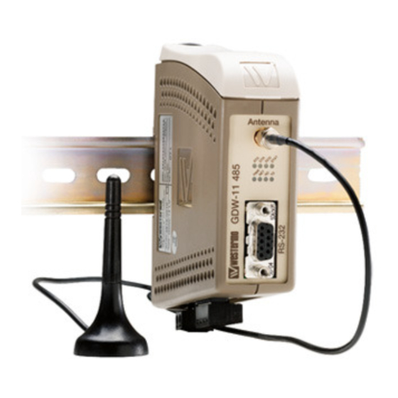
Power port to other 3 kVrms 50 Hz 1 min isolated ports 2 kVrms 50 Hz 1 min (@ rated power <60 V) Any port to any port 0,5 kVrms 50 Hz 1 min (GDW-11 EX) and enclosure Environmental Temperature Operating –25 to +50°C... - Page 13 The GDW-11 provides a reliable data communication link over GSM/GPRS networks. The unit has been designed for use in industrial data communication applications and has several features that are not normally present on standard GSM modems. The GDW-11 is a DIN-rail mounted modem with RS-232 interface in a 9-pin D-sub.
-
Page 14: Functional Description
RS-232 transient terminal Drivers protection protection 9-pos D-sub switches 2-pos Isolated power supply screw terminal GDW-11 485 / GDW-11 485 EX LED’s driver Interface connector RS-485 Drivers 4-pos SIM card Engine connector connector screw protection transient terminal... -
Page 15: Interface Specifications
Interface specifications Power Rated voltage 12 to 48 VDC Operating voltage 10 to 60 VDC Rated current 350 mA @ 12 VDC 150 mA @ 24 VDC 75 mA @ 48 VDC Rated frequency Inrush current I 0.05A Startup current* 0.75A peak Polarity Reverse polarity protected... - Page 16 RS-422/485 Electrical specification EIA/TIA-485 ITU V.11 2-wire or 4-wire twisted pair Data rate 1 200 bit/s – 115.2 kbit/s Data format 7 or 8 data bits, Odd, even or none parity, 1 or 2 stop bits. 9-11 bit words Protocol Transparent Retiming Turn around time...
-
Page 17: Direction Description
Connections GDW-11 SIM interface under lid Antenna interface LED Indicators (for details RS-232 screw terminal see page 19) 5-position Direction Description No. 1 No. 2 No. 3 No. 4 No. 5 – Power connection screw terminal 2-position Direction Description No. 1 –... - Page 18 Connections GDW-11 485 SIM interface under lid Antenna interface LED Indicators (for details see next page) RS-232 D-sub 9-position Direction Description No. 1 Data Carrier Detect (DCD) No. 2 Receive Data (RD) No. 3 Transmit Data (TD) No. 4 Data Terminal Ready (DTR) DIP-switch S2 No.
-
Page 19: Led Indicators
LED Indicators Status Description PWR ON In service Out of service Modem switched ON, Not registered on network Modem switched OFF Slow Flash Modem switched ON, registered on the network Quick Flash Modem switched ON, registered on the network, communication in progress Data received on the RS-232 or RS-485 port No data received on the RS-232 or RS-485 port Data transmitted on the RS-232 or RS-485 port... -
Page 20: Dip Switch Settings
DIP-switch settings DIP-switches under the lid on top of the unit Before DIP-switch settings: Warning! Do not open connected unit Hazardous voltages may occur within this unit when connected to a power supply. Warning! Prevent damage to internal electronics from electro- static discharges (ESD) by discharging your body to a grounding point (e.g. -
Page 21: S2 Dip-Switch
S1 Selection of DTE interface, only in GDW-11 485 / GDW-11 485 EX RS-422/485 interface RS-232 interface 4-wire full duplex 1 2 3 4 1 2 3 4 RS-485 interface 2-wire half duplex 1 2 3 4 S2 DIP-switch RS-422/485 termination, only in GDW-11 485 / GDW-11 485 EX... - Page 22 Slave unit Termination recommendations The RS-422/485 line must be terminated. In the GDW-11 485 / GDW-11 485 EX, the termination is combined with fail-safe functionality. The termination is used to prevent undefined states when the bus is in tri-state condition.
-
Page 23: Installation
Installation Mounting / Removal Before mounting or removing the unit: Warning! Do not open connected unit Hazardous voltages may occur within this unit when connected to a power supply. Warning! Prevent access to hazardous voltages by disconnecting the unit from its power supply. -
Page 24: Antenna Care And Placement
Warning! Please ensure that power is disconnected from the unit before connecting the antenna. Since the GDW-11 is installed in a fixed location, special care must be taken when planning the installation, especially when placing the antenna. The standard antenna shipped with the product is an efficient dual-band antenna designed for the GSM900 and the GSM1800 bands used in the European and most-Asian countries. -
Page 25: Start-Up Guide
Windows configuration tool GD-Tool The GD-Tool is a PC – application program with a graphical interface for easy configuration of the complex functions found in the GDW-11. Please refer to GD-Tool for a complete description of the functionality of the Windows program. - Page 26 Configuration The GDW-11 can be configured from the local DTE interface. When the local interface is used the configuration can be made with AT-commands on the serial interface, or with a PC-based application configuration tool. Factory default settings can also be obtained by using a DIP switch locally.
-
Page 27: Cpwd - Change Password
+CPWD – Change password Syntax: AT+CPWD= <fac>, <oldpwd>, <newpwd> Parameters: <fac> "PS" SIM lock facility with a 8 digits password. "SC" PIN enabled (<mode> = 1) / disabled (<mode> = 0). "AO" BAOC (Barr All Outgoing Calls). “OI” BOIC (Barr Outgoing International Calls). “OX”... - Page 28 +CSQ – Received signal strength Syntax: AT+CSQ. Response syntax: +CSQ: <RSSI>, <BER> Parameters: <RSSI> –113 dBm or less. –111 dBm. 2 to 30 –109 to –53 dBm. –51 dBm or greater. Not known. <BER> BER < 0.2% 0.2% < BER < 0.4% 0.4% <...
-
Page 29: Parity Bit
+ICF – Serial character format Syntax: AT+ICF = <format>, <parity> Parameters: <format> Data bits Parity bit Stop bit(s) – – – <parity> Odd. Even. Mark. Space. None. +IFC – Serial flow control Syntax: AT+IFC = <DCE to DTE>, <DTE to DCE> Parameters: <DCE to DTE>... - Page 30 The modem is by default configured with enhanced mode disabled (AT+WOPEN=0). The advanced mode is needed to get all functionality to work as stated in Datasheets and User Guide for GDW-11. When advanced mode is enabled AT&F will do the following: S0=2;+WRST=1,”024:00”...
- Page 31 Response syntax: +WOPEN: <Mode>[,<IntVersion>[<ExtVersion>]] Parameters: <Mode> Stop the Open-AT embedded application. If the product was running, it resets. Start the Open-AT embedded application. If the product was stopped, it resets. Get the Open AT library versions. Erase the objects flash of the Open-AT embedded application. Erase the Open-AT embedded application.
- Page 32 +WRST – Reset command Syntax. AT+WRST =<Mode>,<Delay> Response syntax: +WRST: <Mode>,<Delay>,<RemainTime> Parameters: <Mode> timer reset is disabled timer reset is enabled <Delay> sets the time before reset Range “000:01”– “168:59” (format hhh:mm) <RemainTime> time before next reset Range “000:01”–“168:59” (format hhh:mm) 6615-2203...
-
Page 33: Application Examples
Set up the connection – The dialling modem AT+CPBS=”SM” Select phonebook as memory storage (this is default) AT+CPBW=1,”nnn” Store the number of the remote modem in the dialling GDW-11 AT&S0 Set DSR signal always high (if this signal is used to trig the DTR) AT%D1 Activates automatic DTR dialling if DTR switches from low (OFF) to high (ON). - Page 34 … GDW-11 connected via CSD-V32 to analogue modem PSTN Network Network Configure the GDW-11 AT+CPIN=xxxx If PIN code required AT&F Set the unit to factory default AT+CBST=7,0,1 Set the bearer to V.32 protocol at 9600 bit/s AT&W Store default settings Configure the TD-36 AT&F...
- Page 35 … GDW-11 connected via CSD-V.110 to ISDN adapter ISDN Network Network Configure the GDW-11 AT+CPIN=xxxx If PIN code required AT&F Set the unit to factory default AT+CBST=71,0,1 Set the bearer to V.110 protocol at 9600 bit/s AT&W Save settings Configure the IDW-90 AT&F...
-
Page 36: Send Message
… GDW-11 sending text message with SMS by activating DTR signal Network Configure the GDW-11 AT+CPIN=xxxx If PIN code required AT&F Set the unit to factory default AT+CMGW=”0762342489”<CR> Store the destination phone number and the text message Alarm text message <ctrl+Z>... - Page 37 … GDW-11 communicates via GPRS and a PC to public server on Internet GPRS Internet Network Configure the GDW-11 AT+CPIN=xxxx If PIN code required AT&F Set the unit to factory default AT+CGATT=1 Make an attach (register) to the GPRS network AT+CGDCONT=1,”IP”,”xxx”...
- Page 38 … GDW-11 communicates via GPRS to another GDW-11 with TCP socket connection. This example uses SIM cards with fixed IP addresses. GPRS Network Configure the GDW-11 with a terminal (both units) AT+WOPEN=1 Enable Advanced mode. Modem will restart AT+CPIN=xxxx If PIN code required AT&F...
- Page 39 … GDW-11 485, two wire half duplex GDW-11 485 Network Termination In this application the GDW-11 485 is set to communicate with a number of units with RS-485 interface. The communication is 2 wire half duplex at 38 400 bit/s. Configure the GDW-11 485 AT+CPIN=xxxx If PIN code required AT&F...
- Page 40 9 Chemin de Chilly 91160 CHAMPLAN Phone:+886 2 8911 1710 Tél : +33 1 69 10 21 00 • Fax : +33 1 69 10 21 01 E-mail: info@westermo.com E-mail : infos@westermo.fr Westermo Teleindustri AB have distributors in several countries, contact us for further information.
Need help?
Do you have a question about the GDW-11 and is the answer not in the manual?
Questions and answers