Table of Contents
Advertisement
Montage-, Installations- und Bedienungsanleitung
Assembly and operating instructions
Notice d'emploi, d'installation et de montage
Montage- en bedieningshandleiding
Montage- och hanteringsanvisning
Istruzioni di montaggio e funzionamento
Instrucciones de montaje y funcionamiento
Filterlüfter
Fan-and-filter unit
Ventilateur à filtre
Ventilator
Filterfläkt
Ventilatore-filtro
Ventilador con filtro
SK 3237.xxx
SK 3238.xxx
SK 3239.xxx
SK 3240.xxx
SK 3241.xxx
SK 3243.xxx
SK 3244.xxx
SK 3245.xxx
Advertisement
Table of Contents

Related Manuals for Rittal SK 3237.xxx


Summary of Contents for Rittal SK 3237.xxx
- Page 1 Filterlüfter Fan-and-filter unit Ventilateur à filtre Ventilator Filterfläkt Ventilatore-filtro Ventilador con filtro SK 3237.xxx SK 3241.xxx SK 3238.xxx SK 3243.xxx SK 3239.xxx SK 3244.xxx SK 3240.xxx SK 3245.xxx Montage-, Installations- und Bedienungsanleitung Assembly and operating instructions Notice d’emploi, d’installation et de montage...
-
Page 3: Table Of Contents
4.4.1 Connection data ... . 8 4.4.2 Overvoltage protection and supply line load ... . . 8 4.4.3 PE conductor connection ..8 Rittal fan-and-filter unit assembly and operating instructions... -
Page 4: Notes On Documentation
They must Useful information and special features. be given to the plant operator. The opera- tor is responsible for storage of the docu- ments so they are readily available when needed. Rittal fan-and-filter unit assembly and operating instructions... -
Page 5: Safety Notes
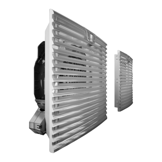
3.1.1 How it works specialist personnel. The fan-and-filter unit is comprised of the following four main components: Fan mo- tor, filter box, louvred grille with function logo and filter medium. Rittal fan-and-filter unit assembly and operating instructions... -
Page 6: Control
SK 3239.1xx) The air throughput volume – Assembly, installation and will be reduced. operating instructions Special filter mats are required for EMC fan-and-filter units Drilling template, self-adhesive (see accessories). Tab. 1: Scope of supply Rittal fan-and-filter unit assembly and operating instructions... -
Page 7: Assembly And Connection
For installation, it is important to ensure the lower mounting holes. that the airflows of fans and built-in com- ponents do not have a negative influence on one another (air short-circuit). Rittal fan-and-filter unit assembly and operating instructions... -
Page 8: Notes On Electrical Installation
4.4.3 PE conductor connection be used in both the fan-and- The PE conductor connection must be filter unit and the outlet filter. connected to the PE conductor system of the overall system. Rittal fan-and-filter unit assembly and operating instructions... -
Page 9: Carrying Out The Electrical
90° and snapped into position. To Please also observe the instructions out- this end, press down on the release button lined under “4.2.1 General”, page 7. of the bayonet connection at the rear of the Rittal fan-and-filter unit assembly and operating instructions... -
Page 10: Commissioning
• Use your finger to pull the function logo in the louvred grille upwards slightly to unlock it. The grille will now flip open by about 70° to allow the filter mat to be re- placed easily. Rittal fan-and-filter unit assembly and operating instructions... -
Page 11: Inspection And Maintenance
– Check the noise generation of the fan. The built-in, maintenance-free fan is moun- – Compressed air cleaning. ted on a friction bearing (SK 3237.xxx, SK 3238.xxx and SK 3239.xxx) or ball bearing (SK 3240.xxx, SK 3241.xxx, SK 3243.xxx to SK 3245.xxx), and is pro-... -
Page 12: Technical Specifications
IP 55 with hose-proof hood IP 55 with hose-proof hood (to EN 60 529) IP 56 with hose-proof hood IP 56 with hose-proof hood Tab. 2: Technical specifications We reserve the right to make technical modifications. Rittal fan-and-filter unit assembly and operating instructions... - Page 13 Protection category – IP 55 with additional fine filter mat or hose-proof hood (to EN 60 529) IP 56 with hose-proof hood Tab. 3: Technical specifications We reserve the right to make technical modifications. Rittal fan-and-filter unit assembly and operating instructions...
- Page 14 Protection category – IP 55 with additional fine filter mat or hose-proof hood (to EN 60 529) IP 56 with hose-proof hood Tab. 4: Technical specifications We reserve the right to make technical modifications. Rittal fan-and-filter unit assembly and operating instructions...
- Page 15 IP 55 with additional fine filter mat or hose-proof category – fine filter mat hood (to EN 60 529) IP 56 with IP 56 with hose-proof hood hose-proof hood Tab. 5: Technical specifications We reserve the right to make technical modifications. Rittal fan-and-filter unit assembly and operating instructions...
-
Page 16: Cut-Out/Drilling Dimensions
B = Width T = Depth Fig. 8: Cut-out dimensions Model No. SK Ø F mm 3237.xxx 100.5 3238.xxx 132.5 3239.xxx 3240.xxx 3241.xxx 3243.xxx 3244.xxx 3245.xxx Tab. 6: Drilling dimensions Fig. 9: Drilling pattern Rittal fan-and-filter unit assembly and operating instructions... -
Page 17: Emc Fan/Outlet Filter
Fig. 10: EMC contact foils Note: Only use original EMC filter mats (see Accessories in the Rittal Catalogue). Rittal fan-and-filter unit assembly and operating instructions... -
Page 18: Connection Diagrams
N PE 3243.100/.110/.600 3245.500/.510/.600 3237.100/.110/.600 3244.100/.110/.600 3238.100/.110/.600 For details, 3239.100/.110/.600 see page 19 24 V DC – N PE L2 L3 PE 3240.100/.110/.600 3237.124 3244.140 3241.100/.110/.600 3238.124 3239.124 3240.124 3241.124 Fig. 11: Connection diagrams Rittal fan-and-filter unit assembly and operating instructions... - Page 19 Control input 0 – 10 V or PWM, galvanically isolated, impedance 100 kΩ +10 V Voltage output 10 V max. 1.1 mA, galvanically isolated, not short circuit-protected Speed Speed output Open Collector, 1 pulse per revolution, galvanically isolated Tab. 7: Explanations to Fig. 12 Rittal fan-and-filter unit assembly and operating instructions...
-
Page 20: Ec Declaration Of Conformity
14 EC declaration of conformity 14 EC declaration of conformity Rittal fan-and-filter unit assembly and operating instructions... - Page 21 Enclosures Power Distribution Climate Control IT Infrastructure Software & Services RITTAL GmbH & Co. KG Postfach 1662 D-35726 Herborn Phone +49(0)2772 505-0 Fax +49(0)2772 505-2319 E-mail: info@rittal.de www.rittal.com...
Need help?
Do you have a question about the SK 3237.xxx and is the answer not in the manual?
Questions and answers