
Related Manuals for Rittal 3238 Series


Summary of Contents for Rittal 3238 Series
- Page 1 Fa a d fi ter u it 3237 xxx 3241 xxx 3238 xxx 3243 xxx 3239 xxx 3244 xxx 3240 xxx 3245 xxx Asse b y a d perati g i structi...
- Page 2 Preface Preface Dear Customer! Thank you for choosing a "Fan-and-filter unit from Rittal. Yours Rittal GmbH & Co. KG Rittal GmbH & Co. KG Auf dem Stützelberg 35745 Herborn Germany Phone: +49(0)2772 505-0 Fax: +49(0)2772 505-2319 E-mail: info@rittal.com www.rittal.com www.rittal.de We are always happy to answer any technical questions regarding our entire range of products.
-
Page 3: Table Of Contents
4.4.1 Connection data ... . 8 4.4.2 Overvoltage protection and supply line load ... . . 9 4.4.3 PE conductor connection ..9 Rittal fan-and-filter unit assembly and operating instructions... -
Page 4: Tes D Cu E Tati
Useful information and special the product. They must be given to the features. plant operator. The operator is responsi- ble for storage of the documents so they are readily available when needed. Rittal fan-and-filter unit assembly and operating instructions... -
Page 5: Safety Tes
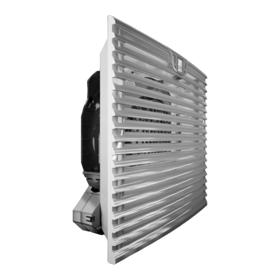
3 1 1 ai c e ts The fan-and-filter unit is comprised of the following four main components: Fan motor, filter box, louvred grille with function logo and filter rmedium. Rittal fan-and-filter unit assembly and operating instructions... -
Page 6: Control
< 10 μm, we recommend the use of fine filter mats. The air throughput volume will be reduced. Special filter mats are required for EMC fan-and-filter units (see accessories). Rittal fan-and-filter unit assembly and operating instructions... -
Page 7: Asse B Y A D C Ecti
15 mm should be observed Deburr the cut-outs. (between drilling templates). Only then is it guaranteed that the louvred grille can be opened without restriction. Rittal fan-and-filter unit assembly and operating instructions... -
Page 8: Connection Data
– If a phase is missing, the fan will not for the overall plant or system. start. If the rotary field is incorrect, the fan will run backwards Rittal fan-and-filter unit assembly and operating instructions... -
Page 9: C Ecti
Choose an appropriate pre-fuse according to the line cross-section (2 x 0.75 – 2.5 mm² multi-wire, 2 x 1.5 – 2.5 mm² fine-wire soldered). Rittal fan-and-filter unit assembly and operating instructions... -
Page 10: Issi I G
Use only original Rittal filters become necessary to change the direction of airflow for technical reasons (space, specific which bear the Rittal logo in order to safeguard the designated pro- component air routing etc.), this is easily tection category, air throughout achieved. -
Page 11: Specti A D Ai Te A Ce
8 I specti st red at te peratures ab ve 70 C r be w 30 C ai te a ce Disposal can be performed at the Rittal f e ectric sh c ! plant. Please contact us for advice. -
Page 12: Tech Ica Specificati S
IP 55 with additional fine filter – IP 55 with hose-proof hood (to IEC 60 529) mat or hose-proof hood IP 56 with hose-proof hood IP 56 with hose-proof hood Technical modifications reserved. Tab. 2: Technical specifications Rittal fan-and-filter unit assembly and operating instructions... - Page 13 -30...+70 IP 54 standard Protection category – IP 55 with additional fine filter mat or hose-proof hood (to IEC 60 529) IP 56 with hose-proof hood Technical modifications reserved. Tab. 3: Technical specifications Rittal fan-and-filter unit assembly and operating instructions...
- Page 14 -30...+70 IP 54 standard Protection category – IP 55 with additional fine filter mat or hose-proof hood (to IEC 60 529) IP 56 with hose-proof hood Technical modifications reserved. Tab. 4: Technical specifications Rittal fan-and-filter unit assembly and operating instructions...
- Page 15 IP 55 with additional fine filter mat or hose-proof category – fine filter mat hood (to IEC 60 529) IP 56 with hose-proof IP 56 with hose-proof hood hood Tab. 5: Technical specifications Technical modifications reserved. Rittal fan-and-filter unit assembly and operating instructions...
-
Page 16: Cut Ut Dri I G Di E Si S
Cut-out dimensions B = Width, T= Depth 3237 xxx 100.5 3238 xxx 132.5 3239 xxx 3240 xxx 3241 xxx 3243 xxx 3244 xxx 3245 xxx Tab. 7: Drilling dimensions Fig. 9: Drilling pattern Rittal fan-and-filter unit assembly and operating instructions... -
Page 17: C Fa Ut Et Fi Ter
Fig. 10: EMC contact foils EMC protection can only be guaranteed when using original Rittal EMC filter media (Model Nos. 3237.066, 3238.066, 3239.066, 3240.066, 3243.066). Rittal fan-and-filter unit assembly and operating instructions... -
Page 18: Ecti Diagra S
3239.100/.110/.600 3243.108/.118 3244.108/.118 3237.108/.118 3238.108/.118 Details, 3239.108/.118 see page 19 24 V DC N PE L2 L3 PE – 3240.100/.110/.600 3237.124 3244.140 3241.100/.110/.600 3238.124 3239.124 3240.108/.118 3240.124 3241.108/.118 3241.124 Fig. 11: Connection diagrams Rittal fan-and-filter unit assembly and operating instructions... - Page 19 Control input 0…10 V or PWM, galvanically isolated, impedance 100 k +10 V Voltage output 10 V max. 1.1 mA, galvanically isolated, not short circuit-protected Speed Speed output Open Collector, 1 pulse per revolution, galvanically isolated Tab. 8: Explanations to fig. 12 Rittal fan-and-filter unit assembly and operating instructions...
- Page 20 14 EC declaration of conformity Rittal fan-and-filter unit assembly and operating instructions...
- Page 21 Enclosures Power Distribution Climate Control IT Infrastructure Software & Services RITTAL GmbH & Co. KG Postfach 1662 D-35726 Herborn Phone +49(0)2772 505-0 Fax +49(0)2772 505-2319 E-mail: info@rittal.de www.rittal.com...
Need help?
Do you have a question about the 3238 Series and is the answer not in the manual?
Questions and answers