
Related Manuals for Rittal 3238.500


Summary of Contents for Rittal 3238.500
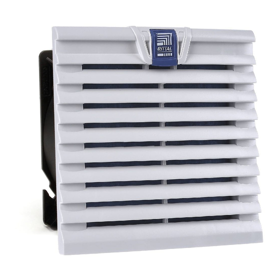
- Page 1 EC fan-and-filter unit 3238.500 3244.500 3239.500 3245.500 3240.500 3245.510 3241.500 3245.600 3243.500 Assembly and operating instructions...
- Page 2 Auf dem Stützelberg 35745 Herborn Germany Phone: +49(0)2772 505-0 Fax: +49(0)2772 505-2319 E-mail: info@rittal.com www.rittal.com www.rittal.de We are always happy to answer any technical ques- tions regarding our entire range of products. Rittal EC fan-and-filter unit assembly and operating instructions...
-
Page 3: Table Of Contents
Inspection and maintenance ....9 Storage and disposal ......10 Technical specifications ...... 11 Cut-out/drilling dimensions ....13 EMC fan/outlet filter ......13 Accessories ........14 Connection diagrams ......16 Declaration of conformity ....18 Rittal EC fan-and-filter unit assembly and operating instructions... -
Page 4: Notes On Documentation
– Use only original spare parts and accessories. grille with function logo and filter medium. – Do not make any changes to the EC fan-and-filter unit other than those described in these and other applicable instructions. Rittal EC fan-and-filter unit assembly and operating instructions... -
Page 5: Control
3245.600 possess an integrated control interface (0 – 10 V or PWM input and tacho signal out- Standard chopped-fibre filter mat or put). These units can be connected either via the Rittal EMC filter mat control unit (Model No. 3235.440), the Rittal sensor for Tab. -
Page 6: Layout Of The Components In The Enclosure
– The fan may be fitted without tools, by simply snap- Notes on electrical connection ping into the preconfigured mounting cut-out. When performing the electrical connection, it is impor- tant to observe all valid national and regional regula- Rittal EC fan-and-filter unit assembly and operating instructions... -
Page 7: Connection Data
◾ Remove the red cover from the electrical connection. Units 3240.xxx, 3241.xxx, 3243.xxx to 3245.xxx are released by pressing the release button of the bayonet connection (see fig. 5), located on the opposite corner from the connection terminal. Rittal EC fan-and-filter unit assembly and operating instructions... -
Page 8: Installing The Control Line
Should it become necessary to change the direc- Replacing the chopped-fibre filter tion of airflow for technical reasons (space, specific ◾ First press the catch of the louvred grille (Rittal logo) component air routing etc.), this is easily achieved. up slightly with one finger (see fig. 6). -
Page 9: Replacing The Pleated Filter
Replacing the pleated filter ◾ First press the catch of the louvred grill (Rittal logo) up slightly with one finger (see fig. 6). ◾ Once it is released, the louvred grille can be dropped open by approx. -
Page 10: Storage And Disposal
Caution! Risk of damage! The EC fan-and-filter unit must not be stored at temperatures above +70 °C or below -25 °C. Disposal can be performed at the Rittal plant. Please contact us for advice. Rittal EC fan-and-filter unit assembly and operating instructions... -
Page 11: Technical Specifications
IP54 standard IP54 with IP54 standard Protection category (to pleated filter IP55 with pleated filter IEC 60 529) IP56 with IP56 with hose-proof hood hose-proof hood Tab. 3: Technical specifications Technical modifications reserved. Rittal EC fan-and-filter unit assembly and operating instructions... - Page 12 IP51 standard Protection category (to filter IP52 with pleated filter IEC 60 529) IP56 with hose- IP56 with hose-proof hood proof hood Tab. 4: Technical specifications Technical modifications reserved. * EMC version Rittal EC fan-and-filter unit assembly and operating instructions...
-
Page 13: Cut-Out/Drilling Dimensions
Next, the four contact foils should be stuck on all- round between the EC fan-and-filter unit and the inside of the enclosure as shown in the following illustration. Fig. 11: Drilling pattern Rittal EC fan-and-filter unit assembly and operating instructions... -
Page 14: Accessories
5 pc(s). 3322.720 3239.xxx ISO coarse 70% 5 pc(s). 3171.120 3240.xxx/3241.xxx ISO coarse 70% 5 pc(s). 3172.120 3243.xxx/3244.xxx/3245.xxx ISO coarse 70% 5 pc(s). 3173.120 Tab. 9: IP54 pleated filter for fan-and-filter unit Rittal EC fan-and-filter unit assembly and operating instructions... - Page 15 NEMA 1, NEMA 12, NEMA 3, NEMA 3R, 3243.xxx/3244.xxx 350 x 480 x 110 1 pc(s). 3243.080 NEMA 4, NEMA 4X 3245.xxx 350 x 480 x 160 NEMA 1, NEMA 12, NEMA 3, NEMA 3R 1 pc(s). 3245.080 Tab. 12: Hose-proof hoods Rittal EC fan-and-filter unit assembly and operating instructions...
-
Page 16: Connection Diagrams
10 % PWM n = min. <10 % PWM n = 0 Fig. 14: Connection diagram 3240.5xx/3241.5xx/3243.5xx/3244.5xx/3245.5xx/3245.6xx Max. speed (as delivered) Adjustable speed Adjustable speed via PWM 1 – 10 kHz Adjustable speed via potentiometer Rittal EC fan-and-filter unit assembly and operating instructions... - Page 17 +10 V Voltage output 10 V max. 1.1 mA, galvanically isolated, not short circuit-protected Speed Speed output Open Collector, 1 pulse per revolution, galvanically isolated Tab. 13: Explanations to fig. 14 Fig. 15: Connection clamps Rittal EC fan-and-filter unit assembly and operating instructions...
-
Page 18: Declaration Of Conformity
Declaration of conformity Declaration of conformity Rittal EC fan-and-filter unit assembly and operating instructions... - Page 19 Notes Rittal EC fan-and-filter unit assembly and operating instructions...
- Page 20 ◾ Climate Control ◾ IT Infrastructure ◾ Software & Services You can find the contact details of all Rittal companies throughout the world here. www.rittal.com/contact RITTAL GmbH & Co. KG Auf dem Stuetzelberg · 35745 Herborn · Germany Phone +49 2772 505-0...
Need help?
Do you have a question about the 3238.500 and is the answer not in the manual?
Questions and answers