Advertisement
Quick Links
For the latest User Installation Guide please visit: www.ergotron.com
User's Guide - English
Guía del usuario - Español
Manuel de l'utilisateur - Français
Gebruikersgids - Deutsch
Benutzerhandbuch - Nederlands
Guida per l'utente - Italiano
Användarhandbok - svenska
888-45-155-W-03 rev. H • 02/14
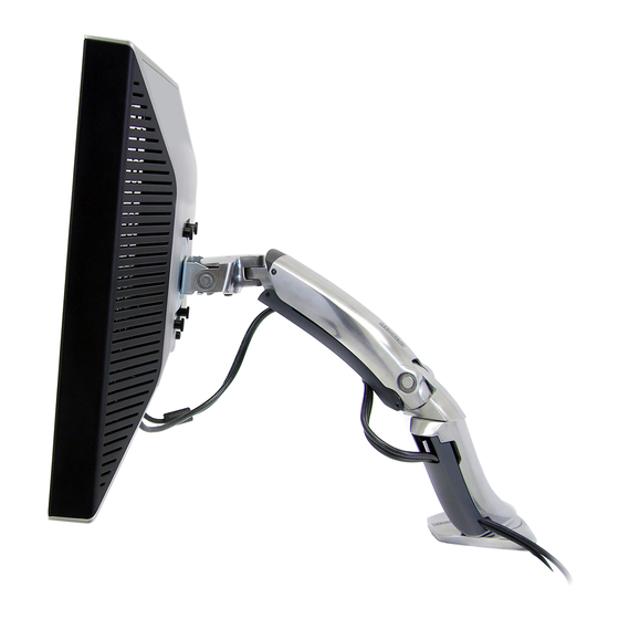
MX Desk Mount LCD Arm
User's Guide
1/10
Advertisement

Related Manuals for Ergotron MX Desk Mount LCD Arm


Summary of Contents for Ergotron MX Desk Mount LCD Arm
- Page 1 User's Guide MX Desk Mount LCD Arm For the latest User Installation Guide please visit: www.ergotron.com User's Guide - English Guía del usuario - Español Manuel de l’utilisateur - Français Gebruikersgids - Deutsch Benutzerhandbuch - Nederlands Guida per l’utente - Italiano Användarhandbok - svenska...
- Page 2 Safety Important! You will need to adjust this product after installation is complete. Make sure all your equipment is properly installed on the product before attempting adjustments. This product should move smoothly and easily through the full range of motion and stay where you set it. If movements are too easy or diffi...
-
Page 3: Features And Specifications
Features & Specifi cations 0˚/90˚ 75˚ 5" 14 - 30 lbs 180˚ (130 mm) (6.35 - 13.61 kg) 360˚ 180˚ 5˚ CAUTION: DO NOT EXCEED MAXIMUM LISTED WEIGHT CAPACITY. SERIOUS INJURY OR PROPERTY DAMAGE MAY OCCUR! Components M4 x 10mm M6 x 10mm M6 x 12mm M3 x 6mm... - Page 4 Choose Mounting Method M6 x 10mm < .63" (16 mm) M6 x 12mm 0.31" - 2"* < 3" (8 - 80 mm) (80 mm) .5" - 1.63" (11 - 41 mm) 1.42" - 2.6" (36 - 66 mm) CAUTION: For secure arm attachment and to avoid equipment damage, plate must make contact with underside of desk on both sides of the hole.
- Page 5 90˚ 0˚ M3 x 6mm Check size of TV/Monitor hole TV/Monitor Hole VESA Adapter Pattern Sizes Confi gurations pattern 100mm (3-15/16”) 75mm (2-15/16”) 75x75mm 100x100mm 100mm (3-15/16”) 100x200mm 200mm (7-7/8”) 200x200mm 200mm (7-7/8”) 200x100mm 888-45-155-W-03 rev. H • 02/14 5/10...
- Page 6 Mount Type A TV/Monitor to Arm 75x75mm 100x100mm 100mm (3-15/16”) 75mm (2-15/16”) 75 x 75mm M4 x 10mm M4 x 10mm 100 x 100mm M4 x 10mm M4 x 10mm 6/10 888-45-155-W-03 rev. H • 02/14...
- Page 7 100x200mm 200x200mm 200x100mm 100mm (3-15/16”) 200mm (7-7/8”) 200mm (7-7/8”) Mount VESA Adapters to Arm based on TV/Monitor hole pattern size (B, C, or D) . M5 x 7mm Mount Type B, C, or D TV/Monitor to Arm M4 x 12mm M5 x 12mm M6 x 12mm NOTE: To reduce M8...
- Page 8 M8M5 KIT Instructions NOTE: Follow this step only if your TV/monitor has M8 holes which need to be reduced to M5. Install M8M5 reducer bushing to TV/Monitor and use M5 x 20 mm monitor screws to secure. M5 x 20mm TV/Monitor Mounting M8 size hole NOTE: Follow this step only for Samsung models using the holder ring.
- Page 9 Cable Routing Adjustment Step Important! You will need to adjust this product after installation is complete. Make sure all your equipment is properly installed on the product before attempting adjustments. This product should move smoothly and easily through the full range of motion and stay where you set it. If movements are too easy or diffi cult or if product does not stay in desired positions, follow the adjustment instructions to create smooth and easy movements.
- Page 10 Breathe - Breathe deeply through your nose. Blink - Blink often to avoid dry eyes. Break • 2 to 3 minutes every 20 minutes • 15 to 20 minutes every 2 hours. For local customer care phone numbers visit: http://contact.ergotron.com 10/10 888-45-155-W-03 rev. H • 02/14...
Need help?
Do you have a question about the MX Desk Mount LCD Arm and is the answer not in the manual?
Questions and answers