Table of Contents
Advertisement
Quick Links
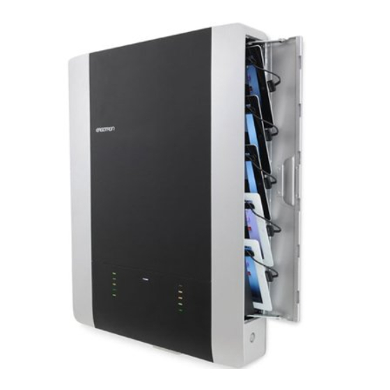
Includes Show & Stow™ technology.
Show
&Stow
< 24lbs. (11 kg)
CAUTION: DO NOT EXCEED MAXIMUM LISTED
WEIGHT CAPACITY. SERIOUS INJURY OR
PROPERTY DAMAGE MAY OCCUR!
D • 08/17
888-61-092-G-00 rev.
Tablet Management Wall Mount 10
Table of Contents
Hazard Symbols Review & Safety ................................................2
Components & Tools ...................................................................2
Mounting Considerations ............................................................3
Set-up ....................................................................................3 - 8
Wood Stud Attachment ...........................................................4
Concrete Attachment ...............................................................6
TM
Cable Routing..............................................................................9
Charging and Syncing ........................................................17 - 18
Cleaning and Maintenance........................................................19
Specifi cations ............................................................................20
Service and Warranty Information ............................................20
Reduce.Reuse.Recycle
1 of 20
Advertisement
Table of Contents

Subscribe to Our Youtube Channel
Related Manuals for Ergotron Tablet Management Wall Mount 10


Summary of Contents for Ergotron Tablet Management Wall Mount 10
-
Page 1: Table Of Contents
Tablet Management Wall Mount 10 Table of Contents Hazard Symbols Review & Safety ..........2 Components & Tools ..............2 Mounting Considerations ............3 Includes Show & Stow™ technology. Set-up ..................3 - 8 Show Wood Stud Attachment ............4 &Stow Concrete Attachment ...............6 Cable Routing................9 <... -
Page 2: Hazard Symbols Review & Safety
WARNING: Because surfaces vary widely and the ultimate mounting method is out CAUTION: Make sure the wall mount bracket of Ergotron’s control, it is imperative that you consult with appropriate engineering, is level, fl ush and snug to the wall surface. -
Page 3: Mounting Considerations
Mounting Considerations Space Requirements: Minimum space needed when removing front cover (for service access only). When mounting to wood stud, at least one screw in the upper mounting If 24” (610 mm) is not available, unit can be removed from 24"... -
Page 4: Wood Stud Attachment
WOOD AND HOLLOW WALL 60”-66" (1524-1676 mm) NOTE: The stud can be located at one of fi ve mounting holes on the top bracket. While the fi rst option (center hole of bracket) is recommended for most cases, you should consult with a construction professional to confi rm which method is best suited for your particular situation. - Page 5 STUD LOCATION OPTIONS 2-5 Hole Option 2 Hole Option 3 Hole Option 4 Extreme Left Hole in Stud Extreme Right Hole in Stud Middle Right Hole in Stud Hole Option 5 Middle Left Hole in Stud 60”-66" (1524-1676 mm) D • 08/17 888-61-092-G-00 rev.
-
Page 6: Concrete Attachment
WOOD AND HOLLOW WALL Drill the three holes in the top bracket that correspond with the hole option determined on previous page. Then drill the two holes in the bottom bracket. NOTE: Use the Ø 3/16” (5 mm) drill bit when drilling directly into the wood stud.Use the Ø... - Page 7 CONCRETE 60”-66" (1524-1676 mm) 60”-66" (1524-1676 mm) Ø 3/8" (10 mm) 3-1/8" (80 mm) WARNING: Mounting holes must be at least 3-1/8” (80mm) deep and must be located within solid concrete, not mortar or covering material. 60”-66" If you drill into an area of concrete that is not solid, reposition (1524-1676 mm) mounting holes until both anchors can be fully inserted into solid 10mm...
- Page 8 M4 x 8mm PENTA Place wrench in Cable Restraint and run power cable through as shown. NOTE: You can push up to 3 feet (1 m) of excess power cord up into the unit for storage. M4 x 8mm D • 08/17 888-61-092-G-00 rev.
-
Page 9: Cable Routing
USB Cable Routing Unplug from wall outlet. Remove front cover and save the Unlock and open door. Remove screws for reattachment. the key to keep door unlocked during service. D • 08/17 888-61-092-G-00 rev. 9 of 20... - Page 10 Plug USB cable into slot 5 on the USB box. Open door, Plug USB end of cable into USB box Close door and push plug through hole in side panel. and route the cable through the two clips as shown. NOTE: Open door before routing cable to make sure...
- Page 11 Plug USB cable into slot 4 on the USB box. Open door, Plug USB end of cable into USB box Close door and push plug through hole in side panel. and route the cable through the two clips as shown. NOTE: Open door before routing cable to make sure...
- Page 12 Plug USB cable into slot 3 on the USB box. Open door, Plug USB end of cable into USB box Close door and and route the cable through the two clips as shown. push plug through hole in side panel. NOTE: Open door before routing cable to make sure...
- Page 13 Plug USB cable into slot 2 on the USB box. Open door, Plug USB end of cable into Close door USB box and route the cable through the and push plug three clips as shown. through hole in side panel. NOTE: Open door before routing cable to make sure...
- Page 14 Plug USB cable into slot 1 on the USB box. Open door, Plug USB end of cable into USB box Close door and push plug through hole in side panel. and route the cable through the four clips as shown. NOTE: Open door before routing cable to make sure...
- Page 15 Attach the next set of USB cables to the right side of the unit starting with slot 10 on the USB box. When complete, reattach front cover. Lock doors. D • 08/17 888-61-092-G-00 rev. 15 of 20...
- Page 16 NOTE: To keep door unlocked, pull key out while NOTE: Tablet screen should face the wall unlocked. when inserting. D • 08/17 888-61-092-G-00 rev. 16 of 20...
-
Page 17: Charging And Syncing
On - fast blink Fault Status. Please make sure all cables are seated correctly and product is operating within specifi ed operating temperature. Contact Ergotron Customer Support if problem continues. 1-10 Individual Status Indicators (ISI) – Sequentially numbered LEDs (1 - 10) corresponding to each tablet slot in the unit:... - Page 18 Tablet Syncing NOTE: Complete the Tablet Charging instructions before syncing. Devices should be charged at least 50% before starting the syncing process. NOTE: The devices will not charge while syncing is in process. To return to charge mode, unplug the USB cable from the TM Wall Mount 10 USB port when syncing is complete.
-
Page 19: Cleaning And Maintenance
The power cord acts as the connect/disconnect device switching power off and on. The socket outlet shall be installed near the equipment and shall be easily accessible. CAUTION: Changes or Modifi cations not expressly approved by Ergotron could void the user’s authority to operate the equipment. Use Safety There are specifi c risks associated with the use of this product (for charging or storage). -
Page 20: Specifi Cations
36.5” x 26.4” x 7.0” (92.6 x 67.0 x 17.7 cm) Shipping weight 43 lb (19.5 kg) Service and Warranty For Service on the Ergotron Tablet Management Wall Mount Charging Station Visit www.ergotron.com www.ergotron.com MADE IN CN 12-345-678 NOTE: When contacting customer service, reference the serial number.
Need help?
Do you have a question about the Tablet Management Wall Mount 10 and is the answer not in the manual?
Questions and answers