
Related Manuals for Allen-Bradley 1738-ADN12


Summary of Contents for Allen-Bradley 1738-ADN12
- Page 1 ArmorPoint I/O DeviceNet Adapters 1738-ADN12, 1738-ADN18, 1738-ADN18P, 1738-ADNX User Manual...
- Page 2 Important User Information Solid state equipment has operational characteristics differing from those of electromechanical equipment. Safety Guidelines for the Application, Installation and Maintenance of Solid State Controls (Publication SGI-1.1 available from your local Rockwell Automation sales office or online at http://www.ab.com/manuals/gi) describes some important differences between solid state equipment and hard-wired electromechanical devices.
- Page 3 Preface Purpose of This Manual This manual describes how to install, configure, and operate your ArmorPoint I/O™ DeviceNet™ Adapters, catalog numbers 1738-ADN12, -ADN18, -ADN18P, and -ADNX. See the following sections: Page: Who Should Use This Manual What the Manual Contains...
- Page 4 Appendix B - Quick Start Appendix C - 1738-ADNX Rules and Guidelines Appendix D - Default Data Maps Learning how to use the 1738-ADN12 Rules and guidelines regarding how to use the Listing of the default data maps for with a ControlLogix system on DeviceNet...
- Page 5 The PointBus that consists of ArmorPoint I/O modules connected to the ArmorPoint DeviceNet adapter. Baudrate Rate of communications between devices on the DeviceNet network. Backplane baudrate is used for the 1738-ADN12, -ADN18, and -ADN18P. Subnet baudrate is used for the 1738-ADNX. Change of State (COS)
- Page 6 Preface Term: Definition: Cyclic DeviceNet communications method in which the adapter sends data cyclically based on a configured time value. Data is independently received cyclically from the sender. Data in both directions can be acknowledged or unacknowledged depending on the run time configuration of the system. MACID Media Access Control Identifier (DeviceNet network address).
- Page 7 ArmorPoint 5V dc Incremental Encoder Module Installation Instructions 1738-IJM23 1738-IN012 ArmorPoint SSI Module Installation Instructions 1738-SSIM23 1738-IN013 ArmorPoint DeviceNet Adapters Installation Instructions 1738-ADN12, -ADN18, -ADN18P, -ADNX 1738-IN014 ArmorPoint PROFIBUS Adapter Installation Instructions 1738-IN015 1738-APB ArmorPoint PROFIBUS Adapter User Manual 1738-UM002...
- Page 8 • ArmorPoint does not support removal and insertion under power (RIUP). When an I/O module is removed, the IP67 seal is broken and the backplane bus is interrupted. • Use Allen-Bradley terminal markers to identify your ArmorPoint I/O modules. For more information on the Allen-Bradley terminal marking kits, see the documents list on page Preface-5.
-
Page 9: Table Of Contents
Wire the DeviceNet Adapters..... . . 1-3 1738-ADN12 and 1738-ADNX ....1-3 1738-ADN18 and 1738-ADN18P . - Page 10 Chapter 4 Configure the DeviceNet Configuration Overview ......4-1 Add the Scanner To Your Network ....4-2 Scanner Subnet Add I/O Modules To Your Network .
- Page 11 Appendix D Default Data Maps 1738-IA2 Input Module ......D-2 1738-IB2 Sink Input Module ..... D-2 1738-IB4 Sink Input Module .
- Page 12 Publication 1738-UM001A-EN-P - February 2005...
-
Page 13: Mount The Adapter And I/O Base
Chapter Install the ArmorPoint DeviceNet Adapters This chapter describes how to install and wire your adapter. See the following sections: Page: Mount the Adapter and I/O Base Set the Node Address Wire the DeviceNet Adapters Chapter Summary and What’s Next Mount the Adapter and To mount the ArmorPoint adapter on a wall or panel, use the screw holes provided in the adapter. -
Page 14: Set The Node Address
Install the ArmorPoint DeviceNet Adapters 5. Mount the terminating base that was shipped with the adapter as the last base in the backplane instead of the base that was shipped with the I/O module. Terminating base Mounting hole Ground connection Latching mechanism holes 43787 Set the Node Address... -
Page 15: Wire The Devicenet Adapters
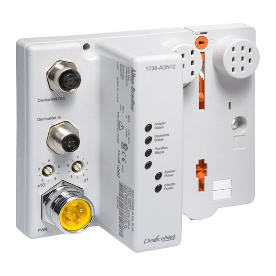
Following are wiring instructions for the ArmorPoint DeviceNet adapters. DeviceNet Adapters 1738-ADN12 and 1738-ADNX Male In Connector Female Out Connector (1738-ADN12) (Subnet Out - 1738-ADNX only) (view into connector) Pin 1 - Drain Pin 2 - +V Pin 3 - -V... -
Page 16: 1738 Armorpoint Devicenet Auxiliary Power
Install the ArmorPoint DeviceNet Adapters 1738 ArmorPoint DeviceNet Auxiliary Power Male In Connector (view into connector) Pin 1 - User Power + Pin 2 - Adapter Power + Adapter/Subnet + (1738-ADNX only) Pin 3 - Adapter Power - Adapter/Subnet - (1738-ADNX only) 43587 Pin 4 - User Power -... - Page 17 Chapter What Is the ArmorPoint DeviceNet Adapter? This chapter describes the ArmorPoint I/O DeviceNet adapter, including descriptions of the adapter’s features and functionality. See the following sections: Page: Use the Adapter Understand the DeviceNet Network and Subnet Adapter Features Communicate Through the Adapter 2-18 Communicate With I/O Modules 2-23...
-
Page 18: Chapter 2 Use The Adapter
DeviceNet software DeviceNet network See page 2-19 for an ArmorPoint I/O modules explanation of the number 1738-IB8M12 1738-OB8EM12 1738-ADN12 sequence. 24V dc In 24V dc Out 1738-ADN12 adapter DeviceNet Out Adapter Status DeviceNet In DeviceNet Status PointBus Status 43852 System... -
Page 19: Set Subnet/Backplane Baudrate
Autobaud enabled as the default- See page 2-12. • Set the adapter baudrate for the Subnet. The default for the 1738-ADN12, -ADN18, and -ADN18P is 1Mbaud. The default for the 1738-ADNX is 125Kbaud - See page 2-9. You set the backplane baudrate for the 1738-ADN12, -ADN18, and -ADN18P. -
Page 20: Configure The Primary Devicenet Network
What Is the ArmorPoint DeviceNet Adapter? 4. Configure the Primary DeviceNet Network Finally, you must configure the adapter for communication with a master (e.g., 1756-DNB). For more information on configuring the DeviceNet network, see Chapter 5, Add the ArmorPoint DeviceNet Adapter to the DeviceNet Scanner’s Scanlist. -
Page 21: Remove And Reinsert Modules On The Backplane
What Is the ArmorPoint DeviceNet Adapter? Remove and Reinsert Modules on the Backplane Removal and Insertion Under Power (RIUP) is not recommended in a ArmorPoint System because of the following reasons. • Removing a module breaks the IP67 seal. • Removing a module breaks the backplane bus. Modules to the right of the removed module will be ‘lost’... -
Page 22: Understand The Devicenet Network And Subnet
What Is the ArmorPoint DeviceNet Adapter? – If modules of the same type are removed and returned to the wrong locations, the adapter identifies the returned modules, updates their MACIDs, and continues operation. The removal and return scenario exists whether the IMPORTANT system is under power or not. -
Page 23: Backplane/Subnet Network
10A of field power). You may use the integrated, isolated 24V dc expansion power unit (1738-EP24DC) to power additional I/O modules, as shown below. 1738-EP24DC ArmorPoint I/O ArmorPoint I/O 1738-ADN12 adapter expansion power unit modules modules 1738-ADN12 1738-IB8M12 1738-OB8EM12... -
Page 24: Adapter Features
What Is the ArmorPoint DeviceNet Adapter? Adapter Features Your adapter uses the following features on both the DeviceNet network and the PointBus: • Self-Test • Field Upgradable Firmware • Fully Configurable Software • Connections • Baudrates Self-Test When power is applied to the adapter, the adapter performs a self-test. - Page 25 • For the 1738-ADN12, -ADN18, and -ADN18P, the PointBus can be configured to operate at 1Mbaud (1000Kbaud). • For the 1738-ADNX, the Subnet can be configured to operate at 125K, 250K, and 500K baud only.
- Page 26 Faulted Node Table) that the error has occurred and must be corrected. Backplane (1738-ADN12, -ADN18, -ADN18P)/Subnet (1738-ADNX) Baudrate EDS parameter Backplane Baudrate is accessible from the primary DeviceNet and sets a specific baudrate for all backplane I/O modules.
- Page 27 What Is the ArmorPoint DeviceNet Adapter? 2-11 The baudrate may not take effect until power is recycled or the I/O modules are reset. Changes to the Backplane/Subnet Baudrate IMPORTANT parameter only take effect if they are downloaded on an individual basis. (For example, if you change the Backplane/Subnet Baudrate and download the changes with additional changes to other features, the Backplane/Subnet Baudrate remains at the...
- Page 28 2-12 What Is the ArmorPoint DeviceNet Adapter? Backplane Autobaud The adapter itself never autobauds on the Subnet. Backplane Autobaud automatically enables or disables Autobaud for all I/O modules currently attached to the backplane. The adapter does not set a specific rate though (as with Backplane Baudrate). If you enable Backplane Autobaud in the adapter or the EDS parameter access that you set from the primary DeviceNet, the adapter only enables the Autobaud in all backplane I/O modules.
- Page 29 What Is the ArmorPoint DeviceNet Adapter? 2-13 Auto Address The EDS parameter Auto Address is available from the primary DeviceNet and lets the user sequentially order the node addresses of backplane I/O modules. This parameter is not a mode but occurs on a single occurrence only.
- Page 30 2-14 What Is the ArmorPoint DeviceNet Adapter? Cycling Node Status Using the Cycling Node Status parameter, you can easily determine the status of any ArmorPoint I/O modules with which the adapter is experiencing problems. A corresponding text string appears, including the MAC ID, and a description of the status code reported in the Node Status Table.
- Page 31 What Is the ArmorPoint DeviceNet Adapter? 2-15 Cycling I/O Mapping Cycling I/O Mapping is an EDS parameter accessible from the primary DeviceNet that shows you how data is mapped in the adapter’s scanlist. The data, as shown below, is listed in order of active modules in the scanlist.
- Page 32 2-16 What Is the ArmorPoint DeviceNet Adapter? The adapter is capable of holding approximately 64K of configuration data for ArmorPoint I/O modules connected to it. The adapter sends configuration data to an I/O module each time connections are created with that module (i.e., power cycle or module insertion to backplane).
- Page 33 What Is the ArmorPoint DeviceNet Adapter? 2-17 Interscan Delay (ISD) Interscan Delay is the time delay between consecutive I/O scans of polled devices. The default setting is 10ms. The ISD=4ms for Auto Start Mode. You can change this parameter in the Module window of the scanner in the RSNetWorx for DeviceNet software.
-
Page 34: Communicate Through The Adapter
2-18 What Is the ArmorPoint DeviceNet Adapter? Transmit Retries Transmit Retries are the maximum number of times that the scanner will attempt to send an I/O message to a device before it times out and generates an error message. You set this parameter in the Module window (from the Advanced button) of the scanner in RSNetWorx for DeviceNet software. -
Page 35: Overview Of The Communication Process
Data may contain: adapter, and I/O modules. • device input data • status data 1738-OB8EM12 1738-IB8M12 1738-ADN12 24V dc Out 24V dc In Although the PCMCIA card is used DeviceNet Out Adapter in this example, you can use other... -
Page 36: Image Table Mapping
2-20 What Is the ArmorPoint DeviceNet Adapter? The four data transfers are not necessarily sequential. Transfers 2 and 3 typically occur more frequently than transfers 1 and 4. Image Table Mapping Your adapter receives data from: • master devices (e.g., scanners) - output data is then passed to ArmorPoint I/O modules •... - Page 37 What Is the ArmorPoint DeviceNet Adapter? 2-21 The following graphic shows how the adapter maps information. DeviceNet Scanner DeviceNet INPUT DATA OUTPUT DATA ArmorPoint DeviceNet Adapter 248 bytes Poll OR COS (inst 2) DeviceNet Poll Buffer 248 + 2 bytes + 2 bytes status DeviceNet Strobe Buffer 6 + 2 bytes...
- Page 38 2-22 What Is the ArmorPoint DeviceNet Adapter? See the I/O Status Word Bit Definitions table for definitions of the first 2 bytes of each I/O message produced by the adapter on DeviceNet. I/O Status Word Bit Definitions Operating Mode Operating Mode Description 0 = Run mode Run - The adapter maps output data to each module on PointBus.
-
Page 39: Communicate With I/O Modules
What Is the ArmorPoint DeviceNet Adapter? 2-23 Communicate With The adapter module supports multiple communication choices. These choices all use the default I/O structure previously described. The I/O Modules adapter’s master (e.g., 1756-DNB) makes the actual communication choice. The choices are: •... -
Page 40: Use Diagnostic Tables
2-24 What Is the ArmorPoint DeviceNet Adapter? Use Diagnostic Tables The adapter maintains three diagnostic tables to manage the flow of data between a processor and a network’s devices. You can access the table over DeviceNet through the Scan Config Object (Class Code 0x90), Instance 1, via the following read-only attributes: •... - Page 41 What Is the ArmorPoint DeviceNet Adapter? 2-25 Node Status Table Numeric Code Definitions Numeric Code: Text Message: Definition: Take this action: Wrong Data Size Data size expected by the device does Reconfigure your module for correct not match scan list entry. transmit and receive data sizes.
-
Page 42: Chapter Summary And What's Next
2-26 What Is the ArmorPoint DeviceNet Adapter? A user program can monitor the Device Failure Bit in the I/O message(s) received from the adapter. When it has determined the bit set, you can read the Faulted Node Table and Node Status Table, using the Explicit Message Program Control Feature of the scanner device, to determine the module experiencing problems and the nature of those problems. - Page 43 Chapter Use Auto Start Mode This chapter describes how to use the Auto Start Mode with your ArmorPoint I/O DeviceNet adapters. See the following sections: Page: Why Use Auto Start Mode? Install the I/O Module Use RSNetWorx for DeviceNet Begin Auto Start Mode Use Custom Configuration Chapter Summary and What’s Next 3-10...
-
Page 44: Why Use Auto Start Mode
Use Auto Start Mode Why Use Auto Start Mode? Auto Start Mode offers you a quick and easy method of getting your ArmorPoint I/O system ‘up and running’. If your ArmorPoint I/O application can use default configuration, you should use Auto Start Mode to easily begin operations. -
Page 45: How Is I/O Data Mapped Using Auto Start Mode
Each node’s I/O data is mapped in the adapter’s memory at the next available byte. This option works best in applications that use Allen-Bradley PLCs and SLCs. Word Boundaries Each node’s I/O data is mapped in the adapter’s memory at the next available word. -
Page 46: Requirement To Using Auto Start Mode
Use Auto Start Mode Requirement To Using Auto Start Mode Your ArmorPoint DeviceNet adapter must be free of I/O connections on DeviceNet when you use Auto Start Mode. If you attempt to use Auto Start Mode after another scanner device has established I/O connections with the adapter, your attempt to use Auto Start Mode will be rejected. -
Page 47: Remove The Module From The Mounting Base
Use Auto Start Mode Remove the Module From the Mounting Base To remove the module from the mounting base: 1. Put a flat blade screwdriver into the slot of the orange latching mechanism. 2. Push the screwdriver toward the I/O module to disengage the latch. - Page 48 Use Auto Start Mode 3. Click OK to synchronize your offline and online configuration. The adapter appears on the screen. 4. Double click on the adapter icon. Double click on this icon. You can either: • Upload configuration from the device to update the software •...
-
Page 49: Begin Auto Start Mode
Use Auto Start Mode Begin Auto Start Mode After you upload the configuration from the device to the software, begin Auto Start Mode (ASM). 1. Double click on the adapter icon to open the adapter properties window. 2. Click on the Parameters tab. 3. - Page 50 Use Auto Start Mode • Check that MACIDs are set to proper values • Check scanlist – browse to Subnet and view scanlist, or look at mapping text – Make sure the scanlist was saved (if not, investigate why?) – If you are using the 1738-ADNX adapter, check the Max(imum) Backplane MACID parameter.
-
Page 51: Use Custom Configuration
Use Auto Start Mode Use the following procedures to attempt to remedy a problem: • Verify that each non-backplane module’s address and baudrate have been set correctly. • Verify that each backplane module is configured to autobaud. The adapter’s EDS parameter Set Backplane Autobaud can be used to set each module’s autobaud parameter. -
Page 52: Chapter Summary And What's Next
3-10 Use Auto Start Mode Chapter Summary and Auto Start Mode was discussed in this chapter. Move on to Chapter 4, Configure the DeviceNet Scanner Subnet or to Chapter 5, Add the What’s Next ArmorPoint DeviceNet Adapter to the DeviceNet Scanner’s Scanlist. Publication 1738-UM001A-EN-P - February 2005... -
Page 53: Configuration Overview
Chapter Configure the DeviceNet Scanner Subnet This chapter describes how to custom configure your scanner for use with ArmorPoint I/O modules. See the following sections: Page: Configuration Overview Add the Scanner To Your Network Add I/O Modules To Your Network Set the Scanner’s Parameters Go On Line Chapter Summary and What’s Next... -
Page 54: Add The Scanner To Your Network
2. Add the scanner as shown below. The scanner appears 1. Expand the list of on the network. communication adapters. 2. Select the 1738-ADN12 ArmorPoint Scanner. The scanner must always exist on the Subnet at IMPORTANT Node 00. Publication 1738-UM001A-EN-P - February 2005... -
Page 55: Add I/O Modules To Your Network
Configure the DeviceNet Scanner Subnet Add I/O Modules To Your Network After you add the scanner, you must add the modules connected to the scanner on the Subnet. In the offline mode, I/O modules must be added individually. Follow these steps: 1. - Page 56 Configure the DeviceNet Scanner Subnet General window Type the scanner’s name here. Type a description here (optional). The scanner’s address must = 0. Click OK to accept the parameters. This window also shows the scanner’s device identity. These IMPORTANT: Configuration changes made fields are read-only.
- Page 57 Configure the DeviceNet Scanner Subnet Module window Set the Interscan Delay here. Set the Foreground to Background Click here to reset the Interscan Delay Poll Ratio here. and Foreground to Background Poll Ratio back to the module default values. Click Advanced to change the advanced module settings, as shown in the following window.
- Page 58 Configure the DeviceNet Scanner Subnet Input window Highlight a module and click Unmap to unmap it. Click Advanced to edit the advanced mapping parameters, as shown below. Click Options to edit the automap Use this pull-down menu to options, as shown below. choose a Memory type.
- Page 59 Configure the DeviceNet Scanner Subnet Following are the remaining configuration windows. ADR window Use this screen to choose Automatic Device Replacement options. You must have loaded each device into RSNetWorx for DeviceNet before you can Load Device Config using this button. Summary window IMPORTANT: You cannot change any configuration parameters on this...
-
Page 60: Go On Line
Configure the DeviceNet Scanner Subnet Go On Line After you set configuration parameters, your scanner must go on line to accept the configuration changes. Follow these steps: 1. Use the Network pulldown to go on line. 1. Click on Network. 2. -
Page 61: Configuration Overview
Chapter Add the ArmorPoint DeviceNet Adapter to the DeviceNet Scanner’s Scanlist This chapter describes how to custom configure your adapter for use with DeviceNet devices. See the following sections: Page: Configuration Overview Add the Adapter to Your Network Set the Adapter’s Parameters Go On Line Chapter Summary Your adapter works on two networks simultaneously and must be... -
Page 62: Add The Adapter To Your Network
Add the ArmorPoint DeviceNet Adapter to the DeviceNet Scanner’s Scanlist You must follow these steps during configuration: 1. Add the adapter to your network 2. Set the adapter’s parameters 3. Add the DeviceNet adapter’s scanlist (see the Quick Start, Appendix B) 4. - Page 63 Add the ArmorPoint DeviceNet Adapter to the DeviceNet Scanner’s Scanlist Set the Adapter’s Parameters After adding the adapter to the network, you must configure it for use with master DeviceNet devices. This chapter shows configuration in the offline IMPORTANT mode. Changes set in this mode do not take effect immediately.
- Page 64 Add the ArmorPoint DeviceNet Adapter to the DeviceNet Scanner’s Scanlist Device Bridging window Use Associate File to associate this configuration file with the configuration file that configures the same Use Clear Association to remove ArmorPoint DeviceNet previously established configuration scanner for communication file associations that no longer apply with ArmorPoint I/O modules.
- Page 65 Add the ArmorPoint DeviceNet Adapter to the DeviceNet Scanner’s Scanlist The following screens show the remaining configuration windows. I/O Data window Connection sizes appear only when the Subnet network file has been associated in the Device Bridging window. These values correspond to the 4 parameters (Poll/COS Connection Consume Size, Poll Connection Produce Size, COS Connection Produce Size, Strobe Connection Produce...
-
Page 66: Go On Line
Add the ArmorPoint DeviceNet Adapter to the DeviceNet Scanner’s Scanlist Go On Line Follow these steps for the adapter to go on line: 1. Use the Network pulldown. 1. Click on Network. 2. Click on Online. The software prompts you to save your configuration changes. Click Yes. -
Page 67: Use The Status Indicators
Guidelines for Using Your Adapter Chapter Summary Use the Status Indicators You can use the status indicators to troubleshoot your adapter. The following graphic shows the adapter’s status indicators. 1738-ADN12 Adapter Status Indicator DeviceNet Status Indicator PointBus Status Indicator System Power Indicator... - Page 68 Troubleshoot the ArmorPoint DeviceNet Adapter Indication Indication Probable Cause DeviceNet Status Device is not on line: - Device attempting to AutoBaud - Device has not completed dup_MAC_ID test - Device not powered - check module status indicator. Flashing Green Device is on line but has no connections in the established state. Green Device is on line and has connections in the established state.
-
Page 69: Guidelines For Using Your Adapter
ArmorPoint I/O system. Input data will hold last state until all previously removed modules are replaced. • Use Allen-Bradley marker cards to identify your ArmorPoint I/O modules. The cards are easily ordered from your Rockwell Automation representative under the Bulletin 1492 number. - Page 70 Troubleshoot the ArmorPoint DeviceNet Adapter Notes: Publication 1738-UM001A-EN-P - February 2005...
- Page 71 Specifications Following are specifications for the 1738 ArmorPoint DeviceNet adapters. ArmorPoint DeviceNet Adapters - 1738-ADN12, -ADN18, -ADN18P, and -ADNX • DeviceNet adapter backplane current output = 1.0 A maximum. See the following list for Expansion I/O Capacity backplane current consumption for each ArmorPoint I/O catalog number and the current consumption for each of the ArmorPoint modules connected to the ArmorPoint DeviceNet adapter.
- Page 72 Specifications ArmorPoint DeviceNet Adapters - 1738-ADN12, -ADN18, -ADN18P, and -ADNX DeviceNet Power Specifications Power Supply Note: In order to comply with CE Low Voltage Directives (LVD), you must use either a NEC Class 2, a Safety Extra Low Voltage (SELV) or a Protected Extra Low Voltage (PELV) power supply to power this adapter.
- Page 73 Specifications ArmorPoint DeviceNet Adapters - 1738-ADN12, -ADN18, -ADN18P, and -ADNX General Specifications (continued) Relative Humidity IEC 60068-2-30 (Test Db, Un-packaged Non-operating Damp Heat): 5-95% non-condensing Shock IEC60068-2-27 (Test Ea, Unpackaged Shock): Operating 30 g Non-operating 50 g Vibration IEC60068-2-6 (Test Fc, Operating):...
- Page 74 Specifications Notes: Publication 1738-UM001A-EN-P - February 2005...
-
Page 75: Appendix B What's In This Appendix
Appendix Quick Start For the 1738-ADNX What’s In This Appendix? In this Quick Start, you will learn how to use the 1738-ADNX with a ControlLogix system on DeviceNet. You will also use one of the 1738-ADNX’s features (Auto Start Mode) in an exercise to automatically configure devices on its Subnet When you complete this quick start you will be familiar with: •... - Page 76 Quick Start For the 1738-ADNX The new Subnet system attributes include: • Most field devices are more than 100 m from the ControlLogix Processor • Previously installed and documented at 500 Kbaud • 1738-ADNX with discrete inputs and outputs for several field devices •...
- Page 77 Quick Start For the 1738-ADNX 4. Click OK. Now that you have created a new DeviceNet project, go on line by clicking the Online icon on the toolbar. 5. A list of the available drivers in RSLinx appears. Drill down from Ethernet into your ControlLogix project through the backplane to your 1756-DNB in slot 3.
- Page 78 Quick Start For the 1738-ADNX RSNetWorx will go on line. A screen similar to the one below will appear: Your system may not look like the above system. (You may have more nodes.) It is only important to verify that you have the 1756-DNB at node 0 and the 1738-ADNX at note 16. After the browse is complete, from the RSNetWorx for DeviceNet main menu select File>Save As.
- Page 79 Quick Start For the 1738-ADNX c. Select the Scanlist tab and when prompted click Download. 12. When the download is complete, add the 1738-ADNX to the scanlist by selecting the 1738-ADNX (node 16) and clicking the single right arrow. A warning window opens that says that the 1738-ADNX does not contain any I/O data.
- Page 80 Quick Start For the 1738-ADNX 15. Click Edit I/O Parameters. Click the 1738-ADNX in the Scanlist and then click Edit I/O Parameters to verify input and output bytes. 16. Verify that nothing is filled in for input and output sizes (both are zero).
- Page 81 Quick Start For the 1738-ADNX 17. Remove the 1738-ADNX from the scanlist for now by clicking the double arrows. Click the double left arrow to remove the 1738-ADNX from the Scanlist. Then verify that the Scanlist is empty. You will return here later after RSNetWorx for...
- Page 82 Quick Start For the 1738-ADNX To properly terminate the 1738-ADNX when using a Subnet, refer to the illustration. 1738-ADNX With Subnet (1738-ADNX Subnet Drop Off Subnet Trunk) Main Trunk Terminator Resistor Terminator Resistor Drop Note that standard DeviceNet terminator resistors are shown in this illustration.
-
Page 83: Review Of The 1738-Adnx Rules And The Macid Parameter
Quick Start For the 1738-ADNX 21. Select the Parameters tab and choose Download. 22. Verify that your window looks similar to the following window. Review of the 1738-ADNX To understand some of the MACID parameters, you should review some of the rules for using the 1738-ADNX. Rules and the MACID Parameter •... - Page 84 B-10 Quick Start For the 1738-ADNX • The 1738-ADNX will automatically maintain the MACIDs of the backplane modules. • Note that the assignment of the MACIDs of the non-backplane subnet modules is manual and is not performed or retained by the 1738-ADNX.
-
Page 85: Review Of Auto Start Mode
Quick Start For the 1738-ADNX B-11 When Auto Start Mode is used, the adapter and connected I/O modules go through the following sequence of events: • Connections are established to I/O modules • The adapter makes Change of State (COS) connections if the I/O module supports COS, if not, the connection is Polled •... - Page 86 B-12 Quick Start For the 1738-ADNX Right now, the 1738-ADNX is not in another scanner’s scanlist so you can use the Auto Start Mode feature. By using Auto Start Mode, the 1738-ADNX will map all the devices on the Subnet and automatically adjust the value for the following parameters: •...
- Page 87 Quick Start For the 1738-ADNX B-13 Notice that parameters 9, 10, 11 and 12 are still at their default of 2 bytes. These values will be filled out for you when this action is complete. Download parameters to the device Monitor icon 4.
- Page 88 B-14 Quick Start For the 1738-ADNX 6. Wait for parameter 8 to return to idle. Then click the Monitor icon to end monitoring. Notice the following: • Parameter 1 has been filled in for you. There are three ArmorPoint I/O modules in the backplane, causing the default to change from 31 to 3.
-
Page 89: Browse The Subnet
Quick Start For the 1738-ADNX B-15 From the RSNetWorx for DeviceNet main menu, select File>Save. You must save your work before moving on. IMPORTANT Browse the Subnet Look at the Subnet at this point to make things more clear. 1. From the RSNetWorx for DeviceNet main menu, select File>New and then select DeviceNet Configuration. - Page 90 B-16 Quick Start For the 1738-ADNX 4. Drill down from Ethernet into your ControlLogix demo box through the backplane to your 1756-DNB in slot 3, channel A, 1738-ADNX and select DeviceNet Subnet as shown below: Last time you browsed the main network This time you will browse the Subnet 5.
- Page 91 Quick Start For the 1738-ADNX B-17 9. Verify your screen appears as shown below. The nodes can be in any order. Verify: • All four are there • They have the correct node numbers On the Subnet, the 1738-ADNX is a scanner and it is always at node 0.
- Page 92 B-18 Quick Start For the 1738-ADNX • Verify your scanlist matches that shown below. • Notice that all the ArmorPoint I/O modules have been added to the scanlist, as you probably expected. You are about to look at the input and output tabs. Based on your selections earlier, all the data should be mapped to word boundaries.
-
Page 93: Inputs And Outputs
Quick Start For the 1738-ADNX B-19 Inputs and Outputs 1. Select the Input tab. A single word is 16 bits. Notice that the mapping is as expected. • The first two bytes (1 byte = 8 bits) are reserved as read only. •... - Page 94 B-20 Quick Start For the 1738-ADNX Scroll down and notice that bytes 0 through 11 = 12 bytes total were enough for the input data. This matches what you observed earlier on the main network: Earlier view of the parameters. The primary network knew you were...
- Page 95 Quick Start For the 1738-ADNX B-21 2. Select the pulldown listbox next to the Memory label in the middle of the window to display the three memory buffer choices. 3. Select each of the choices and view the mapping. You will see that only the COS/cyclic buffer is being used (There are 2 bytes reserved for status in each buffer.
- Page 96 B-22 Quick Start For the 1738-ADNX You should still be looking at the subnet 1738-ADNX Input tab. Now select the Output tab and verify you have the following: • Notice that only the output module 1738-OB4EM12 appears. These two say read only, but since it is an output tab, a better description is...
- Page 97 Quick Start For the 1738-ADNX B-23 6. Select Output Value #1 and notice the exact location of that bit is displayed. You can easily tell that Output Value #1 is in byte 2, bit 1 (see the highlighted portion of byte 2). This information will make it very easy to write your ladder logic later.
-
Page 98: Navigate Between Networks
B-24 Quick Start For the 1738-ADNX From the RSNetWorx for DeviceNet main menu, select File>Save. You must save your work before moving on. IMPORTANT Now all the information is saved in the file SubnetADNX.dnt. Navigate Between Networks A nice feature of RSNetWorx for DeviceNet is the easy way it lets you commission the Subnet. - Page 99 Quick Start For the 1738-ADNX B-25 2. Select the Device Bridging tab. The following window opens. This window lets you define a file that is associated with this one through the 1738-ADNX. Once you specify the associated file, you will be able to jump to that file through a menu selection from the 1738-ADNX.
- Page 100 B-26 Quick Start For the 1738-ADNX From the RSNetWorx for DeviceNet main menu, select File>Save. Now you can observe how you would switch networks. Switch Between Networks 1. Move the cursor over the 1738-ADNX in the network browse window. 2. Press the right mouse button. 3.
- Page 101 Quick Start For the 1738-ADNX B-27 6. Click Associate File to associate the SubnetADNX.dnt file to the main network. 7. Press OK (not cancel) to save the association. Now that they are associated, you can easily jump between the main network and the Subnet and vice versa. Another advantage is that the main network has access to the information saved in Subnet.dnt.
- Page 102 B-28 Quick Start For the 1738-ADNX 13. Change the slot number to 3 (see illustration below) so it matches the 1756-DNBs location in the 1756-Rack. Then click the Scanlist tab. 2. Scanlist tab 1. Slot Number Publication 1738-UM001A-EN-P - February 2005...
- Page 103 Quick Start For the 1738-ADNX B-29 14. Select the 1738-ADNX and then used the single right arrow key to add it to your scanlist. • Notice that you did not get the error message that you received earlier, when you were told that the 1738-ADNX ArmorPoint I/O DeviceNet Adapter does not contain any I/O data.
- Page 104 B-30 Quick Start For the 1738-ADNX Notice the fields have been filled in for you. The values match what was observed earlier. Values observed earlier. • The 1756-DNB scanner will be receiving 12 bytes of data that the 1738-ADNX produces. •...
- Page 105 Quick Start For the 1738-ADNX B-31 17. Click the Input tab and expand the plus sign next to the 1738-ADNX. Expand the plus sign If your mapping does not exactly match this screen, you may need to contact a Rockwell support engineer before moving on.
- Page 106 B-32 Quick Start For the 1738-ADNX Now select the Output tab and find the bit for Output Value #1 on the 1734-OB4EM12. It should be 3:O.Data[0].17 as shown below. (NOTE: Hold your cursor in the box above the highlighted area to cause the last number to display.) You are now ready to write your RSLogix5000 program.
- Page 107 Quick Start For the 1738-ADNX B-33 22. When prompted to save, Click Yes. You have completed the 1738-ADNX Quick Start. Publication 1738-UM001A-EN-P - February 2005...
- Page 108 B-34 Quick Start For the 1738-ADNX Notes: Publication 1738-UM001A-EN-P - February 2005...
-
Page 109: Appendix C
A 1791D CompactBlock I/O module can be used on the Subnet of a 1738-ADNX, the other ArmorPoint DeviceNet adapters (1738-ADN12, -ADN18, and -ADN18P) cannot be used on the Subnet. RULE 5: The 1738-ADNX DeviceNet Subnet is comprised of the adapter (always MACID 0), any backplane I/O modules and ODVA compliant devices attached to the lower DeviceNet connector. - Page 110 Rules and Guidelines For the 1738-ADNX RULE 9: Subnet modules not on the backplane must always have or be assigned MACID’s higher than those of the backplane modules. RULE 10: Power must be supplied for non-backplane Subnet modules. The 1738-ADNX supplies only 5V dc power to the backplane ArmorPoint I/O modules, and 24V dc power to the non-backplane modules via the auxiliary power connector, pins 2 and 3.
- Page 111 Appendix Default Data Maps I/O messages are sent to (consumed) and received from (produced) the ArmorPoint I/O modules. These messages are mapped into the processor’s memory. This appendix lists the default data maps for 1738 ArmorPoint I/O modules. For the default data map of: See page: 1738-IA2 Input Module 1738-IB2 Sink Input Module...
-
Page 112: Default Data Maps
Default Data Maps 1738-IA2 Input Module Message size: 1 Byte Produces (scanner Rx) Consumes (scanner Tx) No consumed data Where: Ch0 = channel 0, Ch1 = channel 1; 0 = OFF, 1 = ON 1738-IB2 Sink Input Module Message size: 1 Byte Produces (scanner Rx) Consumes (scanner Tx) No consumed data... -
Page 113: 1738-Ib8 Sink Input Module
Default Data Maps 1738-IB8 Sink Input Module Message size: 1 Byte Produces (scanner Rx) Consumes (scanner Tx) No consumed data Where: Ch0 = input channel 0, Ch1 = input channel 1, Ch2 = input channel 2 Ch3 = channel 3, Ch4 = input channel 4, Ch5 = input channel 5, Ch6 = input channel 6 Ch7 = channel 7;... -
Page 114: 1738-Oa2 Output Module
Default Data Maps 1738-OA2 Output Module Message size: 1 Byte Produces (scanner Rx) No produced data Consumes (scanner Tx) Not used Channel state Where: Ch0 = output channel 0, Ch1 = output channel 1; 0 = OFF, 1 = ON 1738-OB2E Electronically Protected Output Module Message size: 1 Byte Produces (scanner Rx) -
Page 115: 1738-Ob4E Electronically Protected Output Module
Default Data Maps 1738-OB4E Electronically Protected Output Module Message size: 1 Byte Produces (scanner Rx) Not used Channel status Where: Ch0 = output channel 0, Ch1 = output channel 1, Ch2 = output channel 2, Ch3 = output channel 3; 0 = no error 1 = error Message size: 1 Byte Consumes (scanner Tx) Not used... -
Page 116: 1738-Ov4E Protected Sink Output Module
Default Data Maps 1738-OV4E Protected Sink Output Module Message size: 1 Byte Produces (scanner Rx) Not used Channel status Where: Ch0 = output channel 0, Ch1 = output channel 1, Ch2 = output channel 2, Ch3 = output channel 3; 0 = no error 1 = error Message size: 1 Byte Consumes (scanner Tx) Not used... -
Page 117: 1738-Ie2C Analog Current Input Module
Default Data Maps 1738-IE2C Analog Current Input Module Message size: 6 Bytes Produces (scanner Rx) Input Channel 0 High Byte Input Channel 0 Low Byte Input Channel 1 High Byte Input Channel 1 Low Byte Status Byte for Channel 1 Status Byte for Channel 0 HHA LLA HHA LLA... -
Page 118: 1738-Ie2V Analog Input Module
Default Data Maps 1738-IE2V Analog Input Module Message size: 6 Bytes Produces (scanner Rx) Input Channel 0 - High Byte Input Channel 0 - Low Byte Input Channel 1 - High Byte Input Channel 1 - Low Byte Status Byte for Channel 1 Status Byte for Channel 0 HHA LLA HHA LLA... -
Page 119: 1738-Oe2C Analog Current Output Module
Default Data Maps 1738-OE2C Analog Current Output Module Message size: 4 bytes Consumes (Tx) Output Channel 0 High Byte Output Channel 0 Low Byte Output Channel 1 High Byte Output Channel 1 Low Byte Message size: 2 Bytes Produces (Rx) High Byte - Channel 1 Status Low Byte - Channel 0 Status Not used... -
Page 120: 1738-Ij Encoder/Counter Module
D-10 Default Data Maps 1738-IJ Encoder/Counter Module Message size: 6 Bytes Produces (scanner Rx) Channel 0 value of present counter state (LSW) Channel 0 value of present counter state (MSW) Where: PE = Programming error EF = EEPROM fault status NR = Not ready status bit ZS = Z input status BS = B input status... -
Page 121: 1738-It2I Isolated Thermocouple Input Module
Default Data Maps D-11 1738-IT2I Isolated Thermocouple Input Module Message size: 8 Bytes Produces (scanner Rx) Input Channel 0 - High Byte Input Channel 0 - Low Byte Input Channel 1 - High Byte Input Channel 1 - Low Byte Status Byte for Channel 1 Status Byte for Channel 0 HHA LLA... -
Page 122: 1738-Vhsc 24V Dc High Speed Counter Module
D-12 Default Data Maps 1738-VHSC 24V dc High Speed Counter Module Message size: 6 Bytes Produces (scanner Rx) Channel 0 value of present counter state (LSW) Channel 0 value of present counter state (MSW) Where: PE = Programming error EF = EEPROM fault status NR = Not ready status bit FS = Output fault status bit - bit 10 for output 0, bit 11 for output 1 OS = Output on/off status bit - bit 8 for output 0, bit 9 for output 1... -
Page 123: 1738-232Asc Ascii Module
Default Data Maps D-13 1738-232ASC ASCII Module Default Receive Data Assembly Format (Default Mode) Byte 1 Byte 2 Byte 3 Byte 4 Byte 5-23 Byte 24 Rx Transaction ID Byte Status Byte Reserved Length ASCII Data <CR> (Terminator) Default Transmit Data Assembly Format (Default Mode) Byte 1 Byte 2 Byte 3... - Page 124 D-14 Default Data Maps Notes: Publication 1738-UM001A-EN-P - February 2005...
- Page 125 Index Numbers parameters residence on two networks 1734-IV8 data map simultaneously D-13 1738-232ASC data map setting backplane baudrate D-13 1738-485ASC data map setting parameters 1738-ADNX using MACID parameter what it is? rules on how to use adapter features 1738-ADNX quick start 2-13 auto address assumptions...
- Page 126 auto start mode review setting the scanner’s parameters B-11 using EDS files 1738-ADNX configure the primary DeviceNet 2-13 autoaddress network adapter enabling in RSNetWorx for DeviceNet configure the subnet I/O connections autoaddress backplane modules to and from the adapter adapter contents of manual P-3, 2-9 autobaud...
- Page 127 default data maps device bridging I/O data parameter DeviceNet communications adapter 2-12 backplane autobaud I/O modules 2-10 backplane baudrate installing P-3, 2-6, 2-23 change of state removing from mounting base P-4, 2-6, 2-23 cyclic 2-22 I/O status word bit P-4, 2-6, 2-23 polled 2-24 idle node table...
- Page 128 rules using 1738-ADNX parameters 1738-ADNX MACID adapter foreground to background poll ratio scanner I/O data, adapter adding I/O modules to network map from scanner adding to network scanner configuration overview scanner data alignment data alignment scanner expected packet rate setting expected packet rate setting scanner interscan delay...
- Page 129 2-24 scanner setting in RSNetWorx for using diagnostic tables DeviceNet using the adatpers troubleshooting guidelines using status indicators wire the adapters updating adapter firmware word boundaries using the ControlFlash utility Publication 1738-UM001A-EN-P - February 2005...
- Page 130 Publication 1738-UM001A-EN-P - February 2005...
- Page 131 ___Yes, please call me ___Yes, please email me at __________________________ ___Yes, please contact me via ________________________ Return this form to: Allen-Bradley Marketing Communications, 1 Allen-Bradley Dr., Mayfield Hts., OH 44124-9705 Phone: 440-646-3176 Fax: 440-646-3525 Email: RADocumentComments@ra.rockwell.com Publication ICCG-5.21- January 2001...
- Page 132 PLEASE FASTEN HERE (DO NOT STAPLE) Other Comments PLEASE FOLD HERE NO POSTAGE NECESSARY IF MAILED IN THE UNITED STATES BUSINESS REPLY MAIL FIRST-CLASS MAIL PERMIT NO. 18235 CLEVELAND OH POSTAGE WILL BE PAID BY THE ADDRESSEE 1 ALLEN-BRADLEY DR MAYFIELD HEIGHTS OH 44124-9705...
- Page 134 Rockwell Automation Rockwell Automation provides technical information on the web to assist you in using our products. At http://support.rockwellautomation.com, you can Support find technical manuals, a knowledge base of FAQs, technical and application notes, sample code and links to software service packs, and a MySupport feature that you can customize to make the best use of these tools.
Need help?
Do you have a question about the 1738-ADN12 and is the answer not in the manual?
Questions and answers