Table of Contents
Advertisement
Advertisement
Table of Contents

Related Manuals for Allen-Bradley 1734-ADN


Summary of Contents for Allen-Bradley 1734-ADN
- Page 1 POINT I/O DeviceNet Adapter 1734-ADN, 1734-ADNX User Manual...
- Page 2 Identifies information that is critical for successful IMPORTANT application and understanding of the product. Allen-Bradley, RSNetWorx for DeviceNet, PointBus, and POINT I/O are trademarks of Rockwell Automation. DeviceNet is a trademark of Open DeviceNet Vendor Association.
- Page 3 Summary of Changes Using Change Bars This document contains updated information. Changes are identified by change bars in the margin, as shown to the left. New and Revised The table below lists the new and revised information included in this release of the POINT I/O DeviceNet Adapter user manual.
- Page 4 Summary of Changes Notes: Publication 1734-UM002C-EN-P - July 2003...
- Page 5 Guidelines for Using Your Adapter Preface-5 Conventions Used in This Manual Preface-6 In this manual, we use 1734-ADN(X) to refer to both IMPORTANT the 1734-ADN and 1734-ADNX modules. We use 1734-ADN to refer to only the 1734-ADN module. We use 1734-ADNX to refer to only the 1734-ADNX module.
- Page 6 What the Manual Contains This manual contains the following sections: Chapter 1 - Installing the 1734-ADN(X) Adapter Chapter 2 - What is the 1734-ADN(X) Adapter? Description of how to install and wire the adapter Overview of the adapter’s features and functionality...
- Page 7 The PointBus that consists of POINT I/O modules connected to the 1734-ADN(X) adapter. Baudrate Rate of communications between devices on the DeviceNet network. Backplane baudrate is used for the 1734-ADN. Subnet baudrate is used for the 1734-ADNX. Change of State (COS) DeviceNet communications method in which the adapter sends data based on detection of any changed value within the input data.
- Page 8 Subnet modules’ configurable parameters. When ADR is not active, the scanlist stores only the module identity information. Scanner Operating state of the 1734-ADN(X) when it retrieves I/O data from Subnet modules. Slave A DeviceNet network device that cannot initiate communication (except when configured with COS enabled) but responds to a DeviceNet master device.
- Page 9 If you need more information on these products, contact your local Rockwell Automation/Allen-Bradley distributor, integrator or sales office for assistance. For more information on the documentation, refer to the Allen-Bradley Publication Index, publication SD499. Guidelines for Using Remember the following operational guidelines when using your 1734-ADN(X) adapter.
- Page 10 POINT I/O system. Input data will hold last state until all previously-removed modules are replaced. • Use Allen-Bradley terminal markers to identify your POINT I/O modules. The cards are easily ordered from your Rockwell Automation representative under the Bulletin 1492 number.
-
Page 11: Table Of Contents
Chapter 2 What is the 1734-ADN(X) Adapter? Using the Adapter ....... 2-2 Set Subnet/Backplane Baudrate . - Page 12 Chapter Summary and What’s Next ....4-8 Chapter 5 Adding the 1734-ADN(X) to the Configuration Overview ......5-1 Adding the Adapter to Your Network .
- Page 13 Table of Contents 1734-OB2EP Protected Output Module ... . . D-4 1734-OB4E Electronically Protected Output Module . . . D-4 1734-OV2E Protected Sink Output Module ..D-5 1734-OV4E Protected Sink Output Module .
- Page 14 Table of Contents Publication 1734-UM002C-EN-P - July 2003...
-
Page 15: Installing The 1734-Adn(X) Adapter
Chapter Installing the 1734-ADN(X) Adapter This chapter describes how to install and wire your adapter. For more information about: See page: Installing the Adapter Installing a Replacement DeviceNet Adapter in an Existing System Wiring the Adapter Chapter Summary and What’s Next When properly installed, POINT I/O is grounded through the DIN rail to chassis ground. -
Page 16: Installing The Adapter
Installing the 1734-ADN(X) Adapter Installing the Adapter To install the adapter on the DIN rail prior to installing other base units, proceed as follows. 1. Position the adapter vertically in front of the DIN rail. 2. Press firmly to install the adapter on the DIN rail. The locking mechanism locks the adapter to the DIN rail. - Page 17 Installing the 1734-ADN(X) Adapter 4. Set the node address using the 2-position thumbwheel switch. Valid physical settings range from 00 to 63. Press either the + or - buttons to change the number. You can also set the node address to some value between 64-99.
-
Page 18: Installing A Replacement Devicenet Adapter In An Existing System
Installing a Replacement Your existing control application may be using another DeviceNet adapter (e.g., 1734-PDN) that you want to replace with a DeviceNet Adapter in an 1734-ADN(X) DeviceNet adapter. Remove the existing adapter from Existing System the DIN rail as follows: 1. -
Page 19: Wiring The Adapter
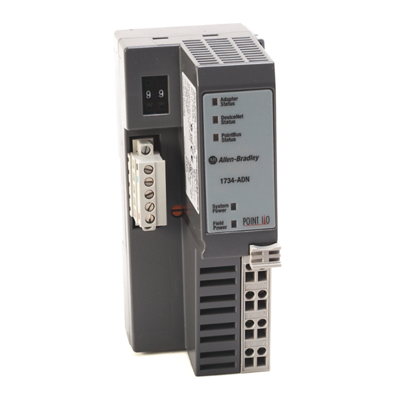
Installing the 1734-ADN(X) Adapter 6. Insert the new adapter into slot 0 using the steps described on page 1-2. 7. Reattach I/O modules to the new adapter. Wiring the Adapter Your adapter’s wiring and network designations are shown below. Adapter Status... -
Page 20: Devicenet Connection Plug Wiring And Subnet
CAN - Low Bare Shield White CAN - High 42514 Chapter Summary and In this chapter, you learned how to install and wire your adapter. Move to chapter 2 to learn about the 1734-ADN(X) adapter. What’s Next Publication 1734-UM002C-EN-P - July 2003... -
Page 21: What Is The 1734-Adn(X) Adapter
Chapter What is the 1734-ADN(X) Adapter? This chapter describes the POINT I/O DeviceNet adapter, including descriptions of the adapter’s features and functionality. For more information about: See page: Using the Adapter Understanding the DeviceNet Network and Subnet Adapter Features Auto Start Mode... -
Page 22: Using The Adapter
What is the 1734-ADN(X) Adapter? Using the Adapter The adapter resides on the primary DeviceNet network and the Subnet simultaneously. The PointBus maintains all DeviceNet network IMPORTANT protocol but also offers configuration capabilities. From this position, the adapter interfaces between DeviceNet devices and POINT I/O modules. - Page 23 I/O modules. POINT I/O modules have Autobaud enabled as the default- See page 2-12. • Set the adapter baudrate for the Subnet. The default for the 1734-ADN is 1Mbaud. The default for the 1734-ADNX is 125Kbaud - See page 2-9. You set the backplane baudrate for the 1734-ADN.
-
Page 24: Configure The Subnet I/O
Finally, you must configure the adapter for communication with a master (e.g., 1756-DNB). For more information on configuring the DeviceNet network, see Chapter 5, Adding the 1734-ADN(X) to the DeviceNet Scanner’s Scanlist. You must understand all of the adapter’s features to effectively use it in your POINT I/O system. -
Page 25: Remove And Reinsert Modules On The Backplane
Remove and Reinsert Modules on the Backplane POINT I/O modules can easily be removed and reinserted on the 1734-ADN(X) backplane. If the removal and reinsertion is not done with caution, you can affect the adapter’s operations and, consequently, the entire POINT I/O application. -
Page 26: Understanding The Devicenet Network And Subnet
What is the 1734-ADN(X) Adapter? – If modules of the same type are removed and returned to the wrong locations, the adapter identifies the returned modules, updates their MAC IDs and continues operation. The removal and return scenario exists whether the IMPORTANT system is under power or not. - Page 27 What is the 1734-ADN(X) Adapter? • Collects I/O data from the Subnet and sends it to devices on the DeviceNet network (e.g., scanners or controllers) • Supplies power to the backplane I/O modules (See Appendix A for power supply rules regarding I/O modules power requirements.)
-
Page 28: Adapter Features
For more information on how to configure your adapter for use with a DeviceNet master, see Chapter 5. For more information on how to configure your adapter for use with Subnet modules, see Chapter 4, Configuring the 1734-ADN(X) Adapter’s SubNet. Publication 1734-UM002C-EN-P - July 2003... - Page 29 • Autobaud - The adapter detects the primary DeviceNet network baudrate and automatically sets its own baudrate to match the network. • For the 1734-ADN, the PointBus can be configured to operate at 1Mbaud (1000Kbaud). Auto Start Mode Auto Start Mode lets you easily get your adapter installed and operating.
- Page 30 2-10 What is the 1734-ADN(X) Adapter? Auto Catalog Replace Auto Catalog Replace corrects errors that might occur when backplane modules of the same type are removed and replaced in the wrong location. If modules of the same type are removed and returned to the wrong locations, the adapter identifies the returned modules, updates their MAC IDs and continues operation.
- Page 31 • 125 Kbaud • 250 Kbaud • 500 Kbaud • 1 Mbaud (available with the 1734-ADN only) When you download this parameter, the adapter sends a command to reset all present I/O modules on the backplane to the new baudrate.
- Page 32 2-12 What is the 1734-ADN(X) Adapter? Backplane Autobaud The adapter itself never autobauds on the Subset. Backplane Autobaud automatically enables or disables Autobaud for all I/O modules currently attached to the backplane. The adapter does not set a specific rate, though (as with Backplane Baudrate).
-
Page 33: Auto Start Mode
What is the 1734-ADN(X) Adapter? 2-13 Auto Address The EDS parameter Auto Address is available from the primary DeviceNet and lets the user sequentially order the node addresses of backplane I/O modules. This parameter is not a mode but occurs on a single occurrence only. - Page 34 2-14 What is the 1734-ADN(X) Adapter? Cycling Node Status Using the Cycling Node Status parameter, you can easily determine the status of any POINT I/O modules with which the adapter is experiencing problems. A corresponding text string appears, including the MAC ID and a description of the status code reported in the Node Status Table.
- Page 35 What is the 1734-ADN(X) Adapter? 2-15 Cycling I/O Mapping Cycling I/O Mapping is an EDS parameter accessible from the primary DeviceNet that shows you how data is mapped in the adapter’s scanlist. The data, as shown below, is listed in order of active modules in the scanlist.
- Page 36 2-16 What is the 1734-ADN(X) Adapter? The adapter is capable of holding approximately 64K of configuration data for POINT I/O modules connected to it. The adapter sends configuration data to an I/O module each time connections are created with that module (i.e., power cycle or module insertion to backplane).
- Page 37 What is the 1734-ADN(X) Adapter? 2-17 Interscan Delay (ISD) Interscan Delay is the time delay between consecutive I/O scans of polled devices. The default setting is 10mS. The ISD=4ms for Auto Start mode. You can change this parameter in the RSNetWorx for DeviceNet software.
-
Page 38: Communicating Through The Adapter
2-18 What is the 1734-ADN(X) Adapter? Transmit Retries Transmit Retries are the maximum number of times that the scanner will attempt to send an I/O message to a device before it times out and generates an error message. You set this parameter in the RSNetWorx for DeviceNet software. -
Page 39: Overview Of The Communication Process
What is the 1734-ADN(X) Adapter? 2-19 Overview of the Communication Process In a typical configuration, the adapter acts as an interface between a DeviceNet scanner (e.g., 1756-DNB) and POINT I/O modules. The example graphic below shows information transferred from a 1756-DNB to POINT I/O modules. -
Page 40: Image Table Mapping
2-20 What is the 1734-ADN(X) Adapter? Image Table Mapping Your adapter receives data from: • master devices (e.g., scanners) - output data is then passed to POINT I/O modules • input modules - input data is passed to the scanner The adapter must map the data it receives to its internal memory before passing it to the appropriate device. - Page 41 What is the 1734-ADN(X) Adapter? 2-21 See Table 2.A for definitions of the first 2 bytes of each I/O message produced by the adapter on DeviceNet. Table 2.A I/O Status Word Bit Definitions Operating Mode Operating Mode Description 0 = Run mode...
-
Page 42: Communicating With I/O Modules
2-22 What is the 1734-ADN(X) Adapter? Communicating with The adapter module supports multiple communication choices. These choices all use the default I/O structure previously described. The I/O Modules adapter’s master (e.g., 1756-DNB) makes the actual communication choice. The choices are: •... -
Page 43: Using Diagnostic Tables
What is the 1734-ADN(X) Adapter? 2-23 Using Diagnostic Tables The adapter maintains three diagnostic tables to manage the flow of data between a processor and a network’s devices. You can access the table over DeviceNet through the Scan Config Object (Class Code 0x90), Instance 1, via the following read-only attributes: •... -
Page 44: Chapter Summary And What's Next
Chapter Summary and In this chapter you learned about the 1734-ADN(X) DeviceNet adapter. Move to Chapter 3 to learn about using Auto Start Mode. What’s Next Publication 1734-UM002C-EN-P - July 2003... -
Page 45: Using Auto Start Mode
Chapter Using Auto Start Mode This chapter describes how to use the Auto Start Mode with your POINT I/O DeviceNet adapter. For more information on: See page: Why Use Auto Start Mode? Installing the Adapter Wiring the Adapter Installing the I/O Modules Adding Non-Backplane Modules to Subnet (1734-ADNX Only) Using RSNetWorx for DeviceNet 3-10... -
Page 46: Why Use Auto Start Mode
For more information on how to write custom configuration for your adapter on DeviceNet, see Chapter 5, Adding the 1734-ADN(X) to the DeviceNet Scanner’s Scanlist. What Does Auto Start Mode Do? When using Auto Start Mode, the adapter: 1. -
Page 47: When The Adapter Uses Auto Start Mode, How Does It Map I/O Data
Each node’s I/O data is mapped in the adapter’s memory at the next available byte. This option works best in applications that use Allen-Bradley PLCs and SLCs. Word Boundaries Each node’s I/O data is mapped in the adapter’s memory at the next available word. -
Page 48: Are There Any Requirements To Using Auto Start Mode
Rockwell Automation representative. • Your 1734-ADN(X) DeviceNet adapter must be free of I/O connections on DeviceNet when you use Auto Start Mode. If another scanner device has established I/O connections with the adapter, the attempt to use Auto Start Mode is rejected. - Page 49 Using Auto Start Mode 3. Insert the DeviceNet network plug and tighten the holding screws. DeviceNet network plug Holding screw 31111-MC Holding screw 4. Set the node address using the 2-position thumbwheel switch. Valid physical settings range from 00 to 63 (Factory setting =63). Press either the + or - buttons to change the number.
- Page 50 Using Auto Start Mode 5. Slide the safety end cap up to remove it. This exposes the backplane and power interconnections. Safety end cap 31112-MC Do not discard the safety end cap. Use this end cap ATTENTION to cover the exposed interconnections on the last mounting base on the DIN rail.
-
Page 51: Wiring The Adapter
Using Auto Start Mode Wiring the Adapter Your adapter’s wiring and network designations are shown below. Adapter Status Adapter Status Network Status Node Address Network Status Thumbwheel Subnet Status Subnet Status 1734-ADNX DeviceNet System Power System Power Connector Field Field Power Power Subnet Connector (1734-ADNX only) -
Page 52: Devicenet And Subnet Connector Plug Wiring
Using Auto Start Mode Terminal Notes Reserved connection connection Chassis Ground Chassis Ground Common Common Voltage Input Apply 12/24V dc. Connects to the internal power bus. Voltage Input DeviceNet and Subnet Connector Plug Wiring Black DeviceNet connection Blue CAN - Low Bare Shield White... -
Page 53: Adding Non-Backplane Modules To Subnet (1734-Adnx Only)
Using Auto Start Mode Adding Non-Backplane The Subnet must be properly terminated. A terminating resistor (included with the 1734-ADNX) must be placed at each end of the Modules to Subnet Subnet trunk segment (see the Rockwell Automation publication (1734-ADNX Only) DeviceNet Cable System Planning and Installation Manual, publication no. -
Page 54: Using Rsnetworx For Devicenet
3-10 Using Auto Start Mode Using RSNetWorx You must use the RSNetWorx for DeviceNet software to configure your adapter. If using a 1734-ADNX adapter, make sure that you for DeviceNet properly configure non-backplane modules for baudrate and MAC ID. Follow the steps below to use Auto Start Mode. 1. -
Page 55: Beginning Auto Start Mode
Using Auto Start Mode 3-11 You can either: • upload configuration from the device to update the software • download configuration from the software to the device 4. Upload configuration from the device. Upload here. Beginning Auto Start Mode 1. After you upload configuration from the device to the software, you must begin Auto Start Mode. - Page 56 Idle), verify that the operation was successful and that each I/O module was added to the adapter’s scanlist. The PointBus LED (1734-ADN) or Subnet Led (1734-ADNX) should be solid green. This indicates only that the adapter is able to establish I/O connections with each module in its scanlist, not that each module on the Subnet was successfully added to its scanlist.
-
Page 57: Using Custom Configuration
For more information on how to write custom configuration for your adapter on DeviceNet, see Chapter 4, Configuring the 1734-ADN(X) Adapter’s SubNet and Chapter 5, Adding the 1734-ADN(X) to the DeviceNet Scanner’s Scanlist. Running Auto Start Mode causes the adapter’s ADR IMPORTANT configuration for the Subnet modules to be reset. -
Page 58: Chapter Summary And What's Next
Using Auto Start Mode Chapter Summary and In this chapter, you learned about the Auto Start Mode. Move on to Chapter 4, Configuring the 1734-ADN(X) Adapter’s SubNet or to What’s Next Chapter 5, Adding the 1734-ADN(X) to the DeviceNet Scanner’s Scanlist. -
Page 59: Configuration Overview
The chapter explains configuration of the adapter for use with POINT I/O modules. For information on how to configure the adapter for use on the DeviceNet Network see Chapter 5, Adding the 1734-ADN(X) to the DeviceNet Adapter’s Scanlist. Configuration Overview You must use the RSNetWorx for DeviceNet software to configure your adapter. -
Page 60: Adding The Scanner To Your Network
Configuring the 1734-ADN(X) Adapter’s SubNet You must follow these steps during configuration: 1. Adding the Scanner to Your Network 2. Adding I/O Modules to Your Network 3. Setting the Scanner’s Parameters 4. Going Online Adding the Scanner to Your Network Follow these steps: 1. -
Page 61: Adding I/O Modules To Your Network
Configuring the 1734-ADN(X) Adapter’s SubNet Adding I/O Modules to Your Network After you add the scanner, you must add the modules connected to the scanner on the Subnet. In the offline mode, I/O modules must be added individually. Follow these steps: 1. - Page 62 Configuring the 1734-ADN(X) Adapter’s SubNet You will see a pop-up screen with a series of tabs. Each tab provides options to write configuration for your adapter. The tabs are shown below and on the following pages. Type the scanner’s name here.
- Page 63 Configuring the 1734-ADN(X) Adapter’s SubNet Set the Interscan Delay here. Click here to reset the Interscan Delay and Set the Foreground to Foreground to Background Poll Ratio back Background Poll Ratio here. to the module default values. Click here to change the Advanced Module Settings, as shown in the screen below.
- Page 64 Configuring the 1734-ADN(X) Adapter’s SubNet Highlight a module and click here to unmap it. Click here to edit the advanced mapping parameters, as shown below. Click here to edit the automap options, Use this pull-down menu to as shown below.
- Page 65 Configuring the 1734-ADN(X) Adapter’s SubNet The screens below show the remaining configuration tabs. Use this screen to choose Automatic Device Replacement options. You must have loaded each device into RSNetWorx for DeviceNet before loading using this button. You cannot change any configuration parameters on this screen.
-
Page 66: Going Online
3. Apply the data to your adapter. Chapter Summary and In this chapter, you learned how to configure the adapter. Move to Chapter 5 to learn how to add the 1734-ADN(X) to the DeviceNet What’s Next Scanner’s scanlist. Publication 1734-UM002C-EN-P - July 2003... -
Page 67: Configuration Overview
Chapter Adding the 1734-ADN(X) to the DeviceNet Scanner’s Scanlist This chapter describes how to custom configure your adapter for use with DeviceNet devices. For more information about: See page: Configuration Overview Adding the Adapter to Your Network Setting the Adapter’s Parameters Going Online Chapter Summary and What’s Next... -
Page 68: Adding The Adapter To Your Network
Adding the 1734-ADN(X) to the DeviceNet Scanner’s Scanlist You must follow these steps during configuration: 1. Adding the Adapter to Your Network 2. Setting the Adapter’s Parameters 3. Adding the DeviceNet scanner’s scanlist (see the Quick Start, Appendix B) 4. Going Online... - Page 69 Adding the 1734-ADN(X) to the DeviceNet Scanner’s Scanlist Setting the Adapter’s Parameters After adding it to the network, you must configure the adapter for use with master DeviceNet devices. This chapter shows configuration in the offline IMPORTANT mode. Changes set in this mode do not take effect immediately.
- Page 70 Adding the 1734-ADN(X) to the DeviceNet Scanner’s Scanlist Use Associate File to associate this configuration file (i.e., configuring the 1734-ADN for communication with DeviceNet) with the Use Clear Association to remove configuration file that previously established configuration configures the same...
- Page 71 Adding the 1734-ADN(X) to the DeviceNet Scanner’s Scanlist The screens below show the remaining configuration tabs. Connection sizes appear only when the Subnet network file has been associated using the Device Bridging tab. These values correspond to the 4 parameters...
-
Page 72: Going Online
DeviceNet network. 3. Click here. 3. Apply the data to your adapter. To learn how to add the 1734-ADN(X) to the scanner’s scanlist, refer to the Quick Start section, Appendix B. Chapter Summary and In this chapter, you learned how to configure the adapter. Move to Chapter 6 if you need troubleshooting assistance. -
Page 73: Use The Status Indicators
Chapter Troubleshooting the 1734-ADN(X) Adapter This chapter describes how to troubleshoot your adapter. To learn how to: See page: Use the Status Indicators Use Guidelines for Using Your Adapter Chapter Summary and What’s Next Use the Status Indicators You can use the status indicators to troubleshoot your adapter. The graphic below shows the adapter’s status indicators. - Page 74 Troubleshooting the 1734-ADN(X) Adapter Use the table below to troubleshoot your adapter. Indicator: Indication: Probable Cause: Take This Action: System Power Any of the following: 1. Not active 1. Check adapter configuration 2. Field power is OFF 2. Turn field power ON 3.
- Page 75 Troubleshooting the 1734-ADN(X) Adapter Indicator: Indication: Probable Cause: Take This Action: Network Status Device is not online Check adapter status - Device is autobauding indicator to determine if - Device has not completed more time is needed to dup_MAC_id test...
-
Page 76: Guidelines For Using Your Adapter
POINT I/O system. Input data will hold last state until all previously-removed modules are replaced. • Use Allen-Bradley marker cards to identify your POINT I/O modules. The cards are easily ordered from your Rockwell Automation representative under the Bulletin 1492 number. - Page 77 Add up the current requirements of the modules you want to use to make sure they do not exceed the amperage limit of the 1734-ADN. (Note: Total expansion up to 63 modules - 13 modules maximum with 1734-ADN - add 1734-EP24DC...
- Page 78 Supply Current 10A maximum 1. For the 1734-ADN, DeviceNet and user supplied power (I/O power) should be powered from separate sources. For the 1734-ADNX, because there are three inputs, for CE purposes, the user supplied power must be separate from the other two (because of surge testing). DeviceNet and the Subnet can be powered from the same source.
- Page 79 Specifications Dimensions Inches 3.0H x 2.16W x 5.25L (Millimeters) (76.2H x 54.9W x 133.4L) Environmental Conditions Operational Temperature -20 to 55 C (-4 to 131 Storage Temperature -40 to 85 C (-40 to 185 Relative Humidity 5 to 95% noncondensing ShockOperating 30g peak acceleration, 11(±1)ms pulse width Non-operating...
- Page 80 Specifications Notes: Publication 1734-UM002C-EN-P - July 2003...
-
Page 81: Appendix B What's In This Appendix
Appendix 1734-ADNX Quick Start What’s In This Appendix? In this Quick Start, you will learn how to use the 1734-ADNX with a ControlLogix system on DeviceNet. You will also use one of the 1734-ADNX’s features (Auto Start Mode) in an exercise to automatically configure devices on its Subnet When you complete this quick start you will be familiar with: •... - Page 82 1734-ADNX Quick Start The new Subnet system attributes include: • Most field devices are more than 100m from the ControlLogix Processor • Previously installed and documented at 500 Kbaud • 1734-ADNX with discrete inputs and outputs for several field devices •...
- Page 83 1734-ADNX Quick Start 3. Select DeviceNet configuration. 4. Click OK. Now that you have created a new DeviceNet project, go online by selecting the Online icon on the toolbar. 5. A list of the available drivers in RSLinx appears. Drill down from Ethernet into your ControlLogix project through the backplane to your 1756-DNB in slot 8.
- Page 84 1734-ADNX Quick Start RSNetWorx will go online. A screen similar to the one below will appear: After the browse is complete, from the RSNetWorx for DeviceNet main menu select File>Save As. 9. Type in MainNetwork (use this exact name to avoid confusion later) as the filename.
- Page 85 1734-ADNX Quick Start c. Select the scanlist tab and when prompted click Download. 12. When the download is complete, add the 1734-ADNX to the scanlist by selecting the 1734-ADNX (node 16) and clicking the single right arrow. A warning window opens that says that the 1734-ADNX does not contain any I/O data.
- Page 86 1734-ADNX Quick Start 15. Click Edit I/O Parameters. Click the 1734-ADNX in the Scanlist and then click Edit I/O Parameters to verify input and output bytes. 16. Verify that nothing is filled in for input and output sizes (both are zero). If you knew how much data was being produced and consumed on the Subnet, you could fill these fields in manually.
- Page 87 1734-ADNX Quick Start 17. Remove the 1734-ADNX from the scanlist for now by clicking the double arrows. Click the double left arrow to remove the 1734-ADNX from the Scanlist. Then verify that the Scanlist is empty. You will return here later after RSNetWorx for DeviceNet knows more about the...
- Page 88 1734-ADNX Quick Start If you are not going to use the subnet, you must still terminate it! You can use the connector provided with the 1734-ADNX and connect two resistors between the white and blue positions. 20475w-res • Termination resistors are 121 Ohms, 1/4 Watt, 1%, Rockwell part number 1785A-C2.
-
Page 89: Review Of The 1734-Adnx Rules And The Mac Id Parameter
1734-ADNX Quick Start 22. Verify that your screen looks similiar to the following screen: Review of the 1734-ADNX To understand some of the MAC ID parameters, you should review some of the rules for using the 1734-ADNX. Rules and the MAC ID Parameter •... - Page 90 B-10 1734-ADNX Quick Start • A unique attribute, Max(imum) Backplane MACID has been added to 1734-ADNX. This value represents the highest node address of a module residing on the backplane. This value must be greater than or equal to the rightmost backplane POINT I/O module, but must be less than that of any non-backplane Subnet module.
-
Page 91: Review Of Auto Start Mode
1734-ADNX Quick Start B-11 When the adapter completes this sequence of events, the POINT I/O modules connected to the adapter are ready to accept connections from a scanner. Although Auto Start Mode lets your adapter IMPORTANT (1734-ADNX) operate with a default configuration, you can choose to manually change the configuration after operation has begun or you can write a custom configuration. - Page 92 B-12 1734-ADNX Quick Start A window describing Auto Start Mode opens. Right now, the 1734-ADNX is not in another scanner’s scanlist so you can use the Auto Start Mode feature. By using Auto Start Mode, the 1734-ADNX will map all the devices on the Subnet and automatically adjust the value for parameters 1, 9, 10, 11, and 12.
- Page 93 1734-ADNX Quick Start B-13 Notice that parameters 9, 10, 11 and 12 are still at their default of 2 bytes. These values will be filled out for you when this action is complete. Download parameters to the device Monitor icon 4.
- Page 94 B-14 1734-ADNX Quick Start • Parameter 3: Verify the Backplane Baudrate is 500 Kbaud. If it is not, you will need to find out why and make the necessary corrections. • Parameter 9, 10 11 and 12 have been filled in for you. Expand the column to view all the...
-
Page 95: Browse The Subnet
1734-ADNX Quick Start B-15 Browse the Subnet Look at the Subnet at this point to make things more clear. 1. From the RSNetWorx for DeviceNet main menu, select File>New and then select DeviceNet Configuration. 2. Click OK. Now that you have a new DeviceNet project created. 3. - Page 96 B-16 1734-ADNX Quick Start From the RSNetWorx for DeviceNet main menu, select File>Save As. 7. Type in SubNet as the filename. 8. Click Save. You must save your work before continuing. IMPORTANT 9. Verify your screen appears as shown below. The nodes can be in any order.
- Page 97 1734-ADNX Quick Start B-17 Make sure you click Upload! You do not want to download over the configuration you just created. 12. When the upload is complete, select the scanlist tab. • Verify your scanlist matches that shown below. • Notice that all the POINT I/O, the DSA, and the RightSight have been added to the scanlist as you probably expected.
-
Page 98: Inputs And Outputs
B-18 1734-ADNX Quick Start Inputs and Outputs 1. Select the Input tab. A single word is 16 bits. Notice that the mapping is as expected. • The first two bytes (1 byte = 8 bits) are reserved as read only. •... - Page 99 1734-ADNX Quick Start B-19 This matches what you observed earlier on the main network: Earlier view of the parameters. The primary network knew you were producing 9 bytes of data. • The data mapped in the 1734-ADNX will be exchanged with the 1756-DNB scanner.
- Page 100 B-20 1734-ADNX Quick Start Note that for the 1734-ADNX, each line in the mapping area represents a byte of data. When you view the 1756-DNB, each line will be 4 bytes of data (double word). Now you are ready to take a look at the output side. Based on the numbers you saw on the main network you expect to see 5 bytes (two of them are going to be reserved status words).
- Page 101 1734-ADNX Quick Start B-21 You should still be looking at the subnet 1734-ADNX Input tab. Now select the Output tab and verify you have the following: • Notice the RightSight does not appear. • It is an input to the scanner - reporting if an object is detected.
- Page 102 B-22 1734-ADNX Quick Start 6. Select Output Value #1 and notice the exact location of that bit is displayed. You can easily tell that Output Value #1 is in Byte 2, Bit 1. This information will make it very easy to write your ladder logic later.
-
Page 103: Navigate Between Networks
1734-ADNX Quick Start B-23 From the RSNetWorx for DeviceNet main menu, select File>Save. You must save your work before moving on. IMPORTANT Now all the information is saved in the file Subnet.dnt. Navigate Between Networks A nice feature of RSNetWorx for DeviceNet is the easy way it lets you commission the Subnet. - Page 104 B-24 1734-ADNX Quick Start 2. Select the Device Bridging tab. The following window opens. This window lets you define a file that is “associated” with this one through the 1734-ADNX. Once you specify the associated file, you will be able to jump to that file through a menu selection from the 1734-ADNX.
- Page 105 1734-ADNX Quick Start B-25 From the RSNetWorx for DeviceNet main menu, select File>Save. Now you can observe how you would switch networks. Switch Between Networks 1. Move the cursor over the 1734-ADNX in the network browse window:. 2. Press the right mouse button. 3.
- Page 106 B-26 1734-ADNX Quick Start 6. Click Associate File to associate the Subnet.dnt file to the main network. 7. Press OK (not cancel) to save the association. Now that they are associated, you can easily jump between the main network and the subnet and vice versa. Another advantage is that the main network has access to the information saved in Subnet.dnt.
- Page 107 1734-ADNX Quick Start B-27 13. Change the slot number to 8 (see illustration below) so it matches the 1756-DNBs location in the 1756-Rack. Then click the Scanlist tab. Scanlist tab Slot Number 14. Select nodes 1, 15, 16 and 20, then use the single right arrow to add them to your scanlist.
- Page 108 B-28 1734-ADNX Quick Start You might have more nodes on your DeviceNet Network, but only add 1, 15, 16 and 20 to the scanlist as shown here. Click to add available devices to scanlist. Click to download to the scanner. Edit I/O Parameters button.
- Page 109 1734-ADNX Quick Start B-29 • The 1756-DNB scanner will be receiving 9 bytes of data that the 1734-ADNX produces such as the state of the RightSight. • The 1756-DNB scanner will be outputting 5 bytes of data that the 1734-ADNX consumes such as the 1734-OB4E outputs. Sometimes it is easy to get confused and reverse the numbers if these values are entered manually (in this case, entering incorrectly input size = 5 and output size = 9).
- Page 110 B-30 1734-ADNX Quick Start You associated the files, so scroll down until you see the RightSight at node 22 on the subnet. 18. Select the RightSight. Notice that its data is at 8:I.Data[3].8 (it starts at bit 8). You will need that address for our RSLogix5000 program.
- Page 111 1734-ADNX Quick Start B-31 You are now ready to write your RSLogix5000 program. 20. Click Apply. 21. Click Yes when prompted to download these changes to the device. 22. Click OK to close the 1756-DNB Output tab. 23. Exit RSNetWorx for DeviceNet. This is not a necessary step, but it will show you that RSLogix5000 can launch RSNetWorx for DeviceNet 24.
- Page 112 B-32 1734-ADNX Quick Start Notes: Publication 1734-UM002C-EN-P - July 2003...
- Page 113 A 1791D CompactBlock I/O module can be used on the Subnet of a 1734-ADNX, a 1734-ADN cannot be used on the Subnet. RULE 5: The 1734-ADNX DeviceNet Subnet is comprised of the adapter (always MAC ID 0), any backplane I/O modules and ODVA compliant devices attached to the lower DeviceNet connector.
- Page 114 1734-ADNX Rules and Guidelines Regarding How to Use the 1734-ADNX RULE 7: The EDS parameter, “Max Backplane MACID” must be set to not be lower than that of any backplane modules. If no backplane modules are used, this value can be set to be 0, allowing modules 1-63 to be attached to the Subnet using DeviceNet cable.
- Page 115 Appendix Default Data Maps I/O messages are sent to (consumed) and received from (produced) the POINT I/O modules. These messages are mapped into the processor’s memory. This appendix lists the default data maps for 1734 POINT I/O and 1734-POINTBlock modules. For the default data map of: See page: 1734-IA2 Input Module...
-
Page 116: 1734-Ia2 Input Module
Default Data Maps 1734-IA2 Input Module Message size: 1 Byte Produces (scanner Rx) Consumes No consumed data (scanner Tx) Where: Ch0 = channel 0, Ch1 = channel 1; 0 = off, 1 = on 1734-IB2 Sink Input Module Message size: 1 Byte Produces (scanner Rx) Consumes... -
Page 117: 1734-Iv2 Source Input Module
Default Data Maps 1734-IV2 Source Input Module Message size: 1 Byte Produces (scanner Rx) Consumes No consumed data (scanner Tx) Where: Ch0 = input channel 0 data Ch1 = input channel 1 data 1734-IV4 Source Input Module Message size: 1 Byte Produces (scanner Rx) Consumes... -
Page 118: 1734-Ob2E Electronically Protected Output Module
Default Data Maps 1734-OB2E Electronically Protected Output Module Message size: 1 Byte Produces (scanner Rx) Not used Channel status Where: 0 = no error 1 = error Message size: 1 Byte Consumes (scanner Tx) Not used Channel state Where: 0 = OFF 1 = ON 1734-OB2EP Protected Output Module Message size: 1 Byte Produces (scanner Rx) -
Page 119: 1734-Ov2E Protected Sink Output Module
Default Data Maps Message size: 1 Byte Consumes (scanner Tx) Not used Channel state Where: 0 = Off 1 = On 1734-OV2E Protected Sink Output Module Message size: 1 Byte Produces (scanner Rx) Not used Channel status Where: 0 = no error 1 = error Message size: 1 Byte Consumes (scanner Tx) Not used... -
Page 120: 1734-Ow2 Relay Sink/Source Output Module
Default Data Maps 1734-OW2 Relay Sink/Source Output Module Message size: 1 Byte Consumes (scanner Tx) Not used Channel state Where: 0 = OFF 1 = ON 1734-OX2 Relay Output Module Message size: 1 Byte Consumes (scanner Tx) Not used Channel state Where: 0 = NO contact OFF, NC contact ON1 = NO contact ON, NC contact OFF 1734-IE2C Analog Current Input Module Message size: 6 Bytes... -
Page 121: 1734-Ie2V Analog Input Module
Default Data Maps Channel Status Table D.A Channel Status Byte Bit 7 Bit 6 Bit 5 Bit 4 Bit 3 Bit 2 Bit 1 Bit 0 Over Range Under Range High High Alarm Low Low Alarm High Alarm Low Alarm CAL Mode Channel Fault 1734-IE2V Analog Input Module... -
Page 122: 1734-Oe2C Analog Current Output Module
Default Data Maps 1734-OE2C Analog Current Output Module Message size: 4 bytes Consumes (Tx) Output Channel 0 High Byte Output Channel 0 Low Byte Output Channel 1 High Byte Output Channel 1 Low Byte Message size: 2 Bytes Produces (Rx) High Byte - Channel 1 Status Low Byte - Channel 0 Status Not used... -
Page 123: 1734-Ij Encoder/Counter Module
Default Data Maps 1734-IJ Encoder/Counter Module Message size: 6 Bytes Produces (scanner Rx) Channel 0 value of present counter state (LSW) Channel 0 value of present counter state (MSW) Where: PE = Programming error EF = EEPROM fault status NR = Not ready status bit ZS = Z input status BS = B input status AS = A input status... -
Page 124: 1734-Im2 Input Module
D-10 Default Data Maps 1734-IM2 Input Module Message size: 1 Byte Produces (Rx) Consumes No consumed data (Tx) Where: Ch0 = channel 0, ICh1 = channel 1; 0 = off, 1 = on 1734-IR2 RTD Input Module Message size: 6 Bytes Produces (scanner Rx) Input Channel 0 - High Byte Input Channel 0 - Low Byte Input Channel 1 - High Byte... -
Page 125: 1734-It2I Isolated Thermocouple Input Module
D-11 Default Data Maps 1734-IT2I Isolated Thermocouple Input Module Message size: 8 Bytes Produces (scanner Rx) Input Channel 0 - High Byte Input Channel 0 - Low Byte Input Channel 1 - High Byte Input Channel 1 - Low Byte Status Byte for Channel 1 Status Byte for Channel 0 HHA L... -
Page 126: 1734-Vhsc 5V Dc High Speed Counter Module
D-12 Default Data Maps 1734-VHSC 5V dc High Speed Counter Module Message size: 6 Bytes Produces (scanner Rx) Channel 0 value of present counter state (LSW) Channel 0 value of present counter state (MSW) Where: PE = Programming error EF = EEPROM fault status NR = Not ready status bit FS = Output fault status bit - bit 10 for output 0, bit 11 for output 1 OS = Output on/off status bit - bit 8 for output 0, bit 9 for output 1... -
Page 127: 1734-232Asc Ascii Module
D-13 Default Data Maps 1734-232ASC ASCII Module Default Receive Data Assembly Format (Default Mode) Byte 1 Byte 2 Byte 3 Byte 4 Byte 5-23 Byte 24 Rx Transaction ID Byte Status Byte Reserved Length ASCII Data <CR> (Terminator) Default Transmit Data Assembly Format (Default Mode) Byte 1 Byte 2 Byte 3... - Page 128 D-14 Default Data Maps Publication 1734-UM002C-EN-P - July 2003...
- Page 129 Index Numbers what it is? adapter features D-13 1734-232ASC data map auto address 2-13 1734-ADNX 2-15 automatic device replacement guidelines on how to use 2-12 backplane autobaud rules on how to use 2-10 backplane baudrate 1734-ADNX MAC ID parameters COS connection produce size 2-14 rules 2-17...
- Page 130 Index communicating with I/O modules 2-22 1734-OV4E 2-20 D-6, D-12 image table mapping 1734-OW2 2-18 mapping data 1734-OX2 2-19 D-12 overview of the process 1734-SSI configuration 1734-VHSC24 D-11 D-12 1734-VHSC5 adding I/O modules to your network default adding the adapter to your network data tables adding the scanner to your network configuring the adapter for DeviceNet...
- Page 131 Index I/O status word bit 2-21 quick start 2-23 idle node table 1734-ADNX 2-20 image table mapping important user information 2-18 inputs and outputs tab Preface-5 related documentation installing I/O modules Preface-5 related products 1-1, 1-4 installing the adapter remove and reinsert modules on 2-17 interscan delay DeviceNet network...
- Page 132 Index troubleshooting using the adatper using status indicators guidelines Preface-5 updating adapter firmware who should use manual Preface-1 Preface-3 using the ControlFlash utility wiring the adapter using diagnostic tables 2-23 Publication 1734-UM002C-EN-P - July 2003...
- Page 133 ___Yes, please call me ___Yes, please email me at __________________________ ___Yes, please contact me via ________________________ Return this form to: Allen-Bradley Marketing Communications, 1 Allen-Bradley Dr., Mayfield Hts., OH 44124-9705 Phone: 440-646-3176 Fax: 440-646-3525 Email: RADocumentComments@ra.rockwell.com Publication ICCG-5.21- January 2001...
- Page 134 PLEASE FASTEN HERE (DO NOT STAPLE) Other Comments PLEASE FOLD HERE NO POSTAGE NECESSARY IF MAILED IN THE UNITED STATES BUSINESS REPLY MAIL FIRST-CLASS MAIL PERMIT NO. 18235 CLEVELAND OH POSTAGE WILL BE PAID BY THE ADDRESSEE 1 ALLEN-BRADLEY DR MAYFIELD HEIGHTS OH 44124-9705...
- Page 136 Rockwell Automation Rockwell Automation provides technical information on the web to assist you in using our products. At http://support.rockwellautomation.com, you can Support find technical manuals, a knowledge base of FAQs, technical and application notes, sample code and links to software service packs, and a MySupport feature that you can customize to make the best use of these tools.
Need help?
Do you have a question about the 1734-ADN and is the answer not in the manual?
Questions and answers