Allen-Bradley POINT I/O ControlNet 1734-ACNR User Manual
Hide thumbs
Also See for POINT I/O ControlNet 1734-ACNR:
- Installation instructions manual (24 pages)
Table of Contents
Advertisement
Advertisement
Table of Contents

Related Manuals for Allen-Bradley POINT I/O ControlNet 1734-ACNR


Summary of Contents for Allen-Bradley POINT I/O ControlNet 1734-ACNR
- Page 1 POINT I/O ControlNet Adapter 1734-ACNR User Manual Allen-Bradley...
- Page 2 (to include intellectual property liability) for actual use based upon the examples shown in this publication. Allen-Bradley publication SGI-1.1, Safety Guidelines for the Application, Installation and Maintenance of Solid-State Control (available from your local Rockwell Automation office), describes...
- Page 3 2. Click on Product Support (http://support.automation.rockwell.com) Your Questions or Comments on this Manual If you find a problem with this manual, please notify us of it on the enclosed How Are We Doing form found at the back of the manual. Allen-Bradley...
- Page 5 It describes the procedures you use to install, program and troubleshoot your module. This manual also includes several application examples. Related Documentation The following documents contain additional information concerning Allen-Bradley products. To obtain a copy, contact your local Allen-Bradley office or distributor. Publication Publication Number...
- Page 6 Preface Publication Publication Number Point I/O Installation Instructions 1734-IN510 Point I/O RS-232 ASCII Module User Manual 1734-UM009 Point I/O RS-232 ASCII Module Installation Instructions 1734-IN588 Point I/O ControlNet Adapter Installation Instructions 1734-IN582 Point I/O 24V dc Expansion Power Supply Installation Instructions 1734-IN058 Point I/O Field Potential Distributor Installation Instructions 1734-IN059...
- Page 7 The messaging service that does not rely on the set-up of a connection between devices before allowing information exchanges. Unscheduled Data transfer that use the remaining time in the NUT after the scheduled transfers have been completed. Allen-Bradley Publication 1734-UM008A-EN-P - February 2003...
- Page 8 Preface Publication 1734-UM008A-EN-P - February 2003...
-
Page 9: Table Of Contents
Change Configuration Data ......4-22 Allen-Bradley An Overloaded 1734-ACNR ......4-25... - Page 10 Chapter 5 Diagnostics Use the Indicators to Troubleshoot ....5-1 Chapter 6 Specifications and Specifications ........6-1 Safety Approvals .
-
Page 11: Chapter 1 Chapter Objectives
ControlNet products compliant with the ControlNet International specification. The 1734-ACNR adapter features include: • a variety of control system solutions • local communication network access through the network access port (NAP) • redundant media Allen-Bradley Publication 1734-UM008A-EN-P - February 2003... -
Page 12: Hardware Components
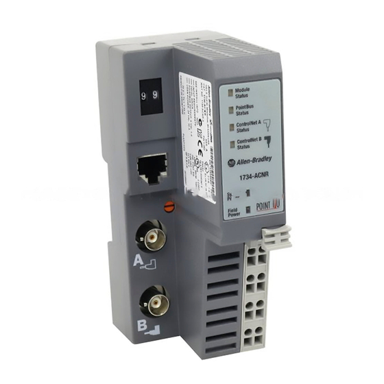
Introducing the ControlNet Adapter Module Hardware Components The adapter module consists of the following major components: 43247 Description Description Coaxial Channel B DIN Rail Locking Screw (orange) Coaxial Channel A System Power and Field Power Indicators Network Access Port (NAP) RTB Removal Handle Node Address Thumbwheel Removable Terminal Block (RTB) -
Page 13: Network Access Port (Nap)
(number 4). These switches are read on powerup to establish the network address of the module. Network address switch settings are described in Chapter 2. For optimum throughput, use lower numbers and assign sequential addresses to ControlNet nodes. Allen-Bradley Publication 1734-UM008A-EN-P - February 2003... - Page 14 Introducing the ControlNet Adapter Module Notes: Publication 1734-UM008A-EN-P - February 2003...
-
Page 15: Chapter 2 Chapter Objectives
1.3A of backplane current. Multiple 1734-EP24DC modules can be used to reach the maximum limit of 63 base modules if 25 or less of these modules are analog or specialty modules. Note: See Chapter 3 for configuration information. Allen-Bradley Publication 1734-UM008A-EN-P - February 2003... -
Page 16: Set The Node Address
Installing Your ControlNet Adapter Module Set the Node Address Set the node address using the 2-position thumbwheel switch. Valid settings range from 01 to 99. Press either the + or - buttons to change the number. Module Status PointBus Status Network Node Address thumbwheel - ControlNet A Status... -
Page 17: Wire The Controlnet Adapter
CHAS CHAS to this supply. V dc 30880 This dc supply will be connected to the internal power bus. Allen-Bradley NC = No Connection CHAS GND = Chassis Ground C = Common V = Supply Publication 1734-UM008A-EN-P - February 2003... -
Page 18: Connect Programming Terminals To The Network Via The Nap
Installing Your ControlNet Adapter Module Connect Programming You can connect programming terminals to the ControlNet network by connecting to the network access port (NAP). The method is Terminals to the Network shown below. via the NAP Using 1784-PCC Communication Card and NAP 1784-PCC Module Status... -
Page 19: Install A Replacement Controlnet Adapter
8. Replace the adjacent module in its base. 9. Connect the ControlNet cable to the adapter. A tap must be used to connect the adapter to the ControlNet cable. Do not directly connect the adapter to the coax cable. Allen-Bradley Publication 1734-UM008A-EN-P - February 2003... - Page 20 Installing Your ControlNet Adapter Module Notes: Publication 1734-UM008A-EN-P - February 2003...
-
Page 21: Chapter 3 Chapter Objectives
The number of connections that can actually be supported on a network is dependent upon: • the ControlNet parameters (NUT, RPI, API) • the POINT I/O configuration by itself (number & types of modules) Allen-Bradley Publication 1734-UM008A-EN-P - February 2003... - Page 22 Plan to Use Your ControlNet Adapter Module • the type of connection to these modules (direct connection, rack connection) When the 1734-ACNR cannot support any more connections, it will not let the connection be opened and issue the error 0x11a. RSLogix5000 will report the following error: For example, if the NUT = 5 ms and the RPI = 10 ms, the adapter can support: •...
-
Page 23: Connection Limit Exceeded 1734-Acnr
134 bytes maximum. Five of these modules configured to a maximum data size will overflow the 1734-ANCR transmit buffer. Proper planning should prevent this error from occurring. (Notice that the 1734-232ASC module default configuration is 80 bytes.) Allen-Bradley Publication 1734-UM008A-EN-P - February 2003... -
Page 24: Rack Connections
Plan to Use Your ControlNet Adapter Module Rack Connections A rack connection supports a group of modules. The 1734-ACNR supports five instances of the rack object that provides the ability to communicate I/O data from all discrete I/O modules in the 1734 bus via one connection pair. -
Page 25: Direct Connections
POINT I/O modules. The 1734-ACNR supports the following objects: Object Number of Instances Device Object Message Router Object Connection Manager Object Unconnected Message Manager Object ControlNet Object Rack Object NVS Object Flash upgrade Allen-Bradley Publication 1734-UM008A-EN-P - February 2003... -
Page 26: Software And Hardware Requirements
Plan to Use Your ControlNet Adapter Module Unconnected messaging lets tools or controllers interface with the CIP objects supported by the POINT I/O modules. The adapter lets controllers, scanners, and software applications address objects for POINT I/O modules on the POINTBUS using unconnected messaging. This requires the adapter to appear as a bridge to these devices. - Page 27 The ControlNet network reserved time for at least IMPORTANT one maximum-sized unscheduled transfer per update interval. Depending on how much time there is for unscheduled messaging, every node may not have a chance to send unscheduled data every update interval. Allen-Bradley Publication 1734-UM008A-EN-P - February 2003...
- Page 28 Plan to Use Your ControlNet Adapter Module Notes: Publication 1734-UM008A-EN-P - February 2003...
-
Page 29: What's In This Chapter
• change configuration data • an overloaded 1734-ACNR Add Modules to the You must add modules to the I/O configuration before you begin to configure them. I/O Configuration Select a Controller 1. Start RSLinx. Allen-Bradley Publication 1734-UM008A-EN-P - February 2003... - Page 30 Configure the 1734 POINT I/O ControlNet Adapter You need the 1756-CNBR Series D ControlNet bridge to access the 1734-ACNR module from the ControlLogix network. The 1784-PCC is the Personal Computer ControlNet network interface card that we use to talk to the networks. 2.
-
Page 31: Select A Communication Module
1. Click on I/O Configuration on the left side of the screen to highlight it. 2. Right click on I/O Configuration and choose New Module. You see this window. Allen-Bradley 3. Choose the 1756-CNBR/D ControlNet Bridge. Publication 1734-UM008A-EN-P - February 2003... - Page 32 Configure the 1734 POINT I/O ControlNet Adapter 4. Choose OK. 5. You see the Module Properties screen. 6. Enter the Module name and slot number. 7. Choose Finish. Notice that the Bridge is now under the I/O Configuration. Publication 1734-UM008A-EN-P - February 2003...
-
Page 33: Select The 1734-Acnr
Select Module Type window. 2. Under Type, enter 1734. This will take you to the first 1734 product - the 1734-ACNR. 3. Choose OK to select the 1734-ACNR adapter. The Module Properties window opens. Allen-Bradley Publication 1734-UM008A-EN-P - February 2003... - Page 34 Configure the 1734 POINT I/O ControlNet Adapter 4. Enter the name, node number, and chassis size following the guidelines below. • the chassis size equals 1 for the adapter + the number of POINT I/O modules installed (physically present on the POINT I/O backplane) The chassis size is the total number of modules IMPORTANT...
-
Page 35: Add Discrete Modules To The I/O Configuration
New Module selection will be dimmed out and disabled. You will not be able to add any more POINT I/O modules until the 1734-ACNR chassis size is increased. Allen-Bradley Publication 1734-UM008A-EN-P - February 2003... - Page 36 Configure the 1734 POINT I/O ControlNet Adapter 2. Choose the 1734-OB2E from the list of modules. At the bottom of the Select Module Type screen, you can choose Clear All and then select a type of module (analog, digital, specialty) to narrow your search. 3.
-
Page 37: Add Analog Modules To The I/O Configuration
1. Highlight the 1734-ACNR under I/O Configuration. I/O Configuration 2. Right click and select New Module. 3. Click on the Clear All button. 4. Click on Analog so that a check mark appears in the box. Allen-Bradley Publication 1734-UM008A-EN-P - February 2003... - Page 38 4-10 Configure the 1734 POINT I/O ControlNet Adapter 5. Choose the 1734-IE2V. 6. Enter a name (optional), slot number, and comm format. You can only choose the input data or listen only option as the comm format since it is an analog module and must be a direct connection.
-
Page 39: Download The Program To The Controller
Follow this procedure to download the program we just saved to the ControlLogix controller. the Controller 1. From the main menu, choose Communications>Who-Active. 2. Select the slot where the processor is located in the chassis. Allen-Bradley Publication 1734-UM008A-EN-P - February 2003... - Page 40 4-12 Configure the 1734 POINT I/O ControlNet Adapter 3. Choose Set Project Path. 4. Choose Download. 5. Choose Download. You see this window. Publication 1734-UM008A-EN-P - February 2003...
-
Page 41: Configure The 1734-Acnr Adapter
1734-ACNR adapter hardware. This procedure will synchronize the chassis size value from the RSLogix5000 software into the 1734-ACNR hardware. 1. Highlight the 1734-ACNR and right-click to choose Properties. 2. Click the Chassis Size tab. Allen-Bradley Publication 1734-UM008A-EN-P - February 2003... - Page 42 4-14 Configure the 1734 POINT I/O ControlNet Adapter 3. Click Set Chassis Size in Module. Value from RSLogix5000 Value stored in 1734-ACNR 4. Read and acknowledge the warning screen. 5. Click OK to continue. Notice the chassis size in the module has been modified to 4. 6.
-
Page 43: Schedule I/O Module Connections
I/O module connections yet. You’ll do that through RSNetWorx for ControlNet. Schedule I/O 1. Start RSNetWorx for ControlNet. Module Connections 2. From the File menu, choose New. 3. Click OK. 4. Choose Network>Online. Allen-Bradley Publication 1734-UM008A-EN-P - February 2003... - Page 44 4-16 Configure the 1734 POINT I/O ControlNet Adapter 5. Choose the PCC interface card. 6. Click OK. When you are online, you’ll see the following screen. 7. You will see a window where there is a mismatch between the offline and online data. Publication 1734-UM008A-EN-P - February 2003...
- Page 45 This will save you time because the controller will not have to search for all of the node addresses. • Media redundancy on channel A, B or A and B 11. Click OK. Allen-Bradley Publication 1734-UM008A-EN-P - February 2003...
- Page 46 4-18 Configure the 1734 POINT I/O ControlNet Adapter 12. Click Save. Enter a name for the file and a location in which to save the file. You will see this window. 13. Click OK. Notice the I/O OK is solid green in RSLogix. Also notice that all of the yellow warning triangles are gone in the I/O Configuration.
-
Page 47: Access Module Data Via The 1734-Acnr Adapter
• # = slot number of POINT I/O module • C = configuration, I = input, O = output • When there is no slot number, that is the rack optimized data. • ACNR:1:C (1734-OB2E module) configuration data Allen-Bradley Publication 1734-UM008A-EN-P - February 2003... - Page 48 4-20 Configure the 1734 POINT I/O ControlNet Adapter • ACNR:1:I (1734-OB2E module) (fault status) input data (open wire and overcurrent) • ACNR:1:O (1734-OB2E module) output data • ACNR:2:C (1734-IB2 module) configuration data • ACNR:2:I (1734-IB2 module) input data It is also possible to send configurations via CIP messages.
- Page 49 Configure the 1734 POINT I/O ControlNet Adapter 4-21 • ACNR:3:C (1734-IE2V module) configuration data • ACNR:3:I (1734-IE2V module) input data Allen-Bradley Publication 1734-UM008A-EN-P - February 2003...
-
Page 50: Change Configuration Data
4-22 Configure the 1734 POINT I/O ControlNet Adapter • ACNR:I or ACNR:O (rack optimized inputs/outputs) Use the controller tags in your ladder program to read input data or write output data. • For RSLogix5000 programming instructions, refer to RSLogix 5000 Configuration and Programming for the Logix5000 Family of Controllers, publication no. - Page 51 Configure the 1734 POINT I/O ControlNet Adapter 4-23 4. Select Properties. 5. Click on the Connection tab. 6. Select Inhibit Module. 7. Click Apply. 8. Click OK to confirm disabling the connection. Allen-Bradley Publication 1734-UM008A-EN-P - February 2003...
- Page 52 4-24 Configure the 1734 POINT I/O ControlNet Adapter The connection is now inhibited. 9. Click on Inhibit Module so that the check mark disappears. This will disable the inhibit module function. 10. Click Apply to download the configuration data. Note that the connection is now running. Publication 1734-UM008A-EN-P - February 2003...
-
Page 53: An Overloaded 1734-Acnr
• In this "no connections allowed state", the adapter will continue to process messages. This will give you the option of issuing a module reset to leave the "no connections allowed" state. Allen-Bradley Publication 1734-UM008A-EN-P - February 2003... - Page 54 4-26 Configure the 1734 POINT I/O ControlNet Adapter If this overloaded state is ever encountered, you will not have to troubleshoot the connections being made and dropped - the 1734-ACNR overload error will be latched. Alternatively, if you anticipate this event in a fault situation, you can clear the fault via your program.
-
Page 55: Use The Indicators To Troubleshoot
Probable Cause Field Power Not active; field power is off Green Power on; 24V present System Power Not active; field power is off or dc-dc converter problem Green System power on; dc-dc converter active (5V) Allen-Bradley Publication 1734-UM008A-EN-P - February 2003... - Page 56 Diagnostics Indication Probable Cause Module Status No power applied to device Alternating Red/Green LED powerup test (module self-test) Flashing Red Recoverable fault has occurred: • Firmware (NVS) update • MAC ID changed • CPU load exceeded Solid Red Unrecoverable fault has occurred: •...
- Page 57 Adapter on-line with no connections established • adapter chassis size has not been configured • controller in program/idle mode • ControlNet cable break Green Adapter on-line with connections established (normal operation, in run mode) Allen-Bradley Publication 1734-UM008A-EN-P - February 2003...
- Page 58 Diagnostics Publication 1734-UM008A-EN-P - February 2003...
-
Page 59: Chapter 6 Specifications
75mA 1734-IJ2 160mA 1734-IK2 160mA 1734-IR2 220mA 1734-IT2I 175mA 1734-SSI 110mA 1734-232ASC 75mA 1734-VHSC5 180mA 1734-VHSC24 180mA ControlNet Communication 5Mbits/s (fixed value) Rate Module Location Starter module - left side of the 1734 system Allen-Bradley Publication 1734-UM008A-EN-P - February 2003... - Page 60 Specifications and Safety Approvals Power Supply Specifications Input Voltage Rating 24V dc nominal 10-28.8V dc range Field Side Power Requirements 24V dc (+20% = 28.8V dc maximum) @ 425mA maximum Inrush Current 6A maximum for 10ms Interruption Output voltage will stay within specifications when input drops out for 10ms at 10V with maximum load.
- Page 61 Refer to ‘Industrial Automation Wiring and Grounding Guidelines”, publication 1770-4.1, for wiring category information and guidelines. See the Product Certification link at www.ab.com for Declarations of Conformity, Certificates, and other certification details. Allen-Bradley Publication 1734-UM008A-EN-P - February 2003...
-
Page 62: Safety Approvals
Specifications and Safety Approvals Safety Approvals The following information applies Informations sur l’utilisation de cet when operating this equipment in équipement en environnements hazardous locations: dangereux : Products marked “CL I, DIV 2, GP A, B, C, D” Les produits marqués "CL I, DIV 2, GP A, B, C, are suitable for use in Class I Division 2 D"... -
Page 63: 1734 Point I/O
2 Channel Analog Current Input 1734-IE2V/C 2 Channel Analog Voltage Input 1734-IR2/C 2 Channel RTD Input 1734-IT2I/C 2 Channel Thermocouple Input, Isolated 1734-OE2C/C 2 Channel Analog Current Output 1734-OE2V/C 2 Channel Analog Voltage Output Allen-Bradley Publication 1734-UM008A-EN-P - February 2003... -
Page 64: Valid Number Ranges For Rslogix5000 Data Types
1734-POINT I/O Module/RSLogix5000 Controller Tag Reference 1734 POINT I/O RSLogix5000 Module Description Catalog Number Specialty I/O 1734-232ASC/C 1 Channel ASCII Interface Module 1734-IJ/C 1 Channel 5V DC Encoder/Counter 1734-IK/C 1 Channel 15-24V DC Encoder/Counter 1734-SSI/C 1 Channel Synchronous Serial Interface 1734-VHSC24/C 1 Channel 15-24V DC Very High Speed Counter 1734-VHSC5/C... -
Page 65: Discrete 2 Point Input
To enter Filter values from +32,768 to +65,535 µs, use this conversion formula: Desired Filter Value (in µs) - 65536 = Entered Filter Value (in µs). Example: For a 40ms filter time, 40000 - 65536 = -25536 Allen-Bradley Publication 1734-UM008A-EN-P - February 2003... -
Page 66: Discrete 4 Point Input
1734-POINT I/O Module/RSLogix5000 Controller Tag Reference Discrete 4 POINT Input 1734-IB4 4 POINT 10V-28V DC Input, Sink 1734-IV4 4 POINT 10V-28V DC Input, Source Configuration Data Data Type Default Valid Data Values Value -32,768 to 32,767 µs * Filter Off On Time - POINT 0 1,000 (0 - 65,535) -32,768 to 32,767 µs *... -
Page 67: Discrete 2 Point Output - Without Diagnostic Status
Program Value - POINT 0, 1 SINT, BIT 0=Off 1=On Input Data Data Type Default Valid Data Values Value None Output Data Data Type Default Valid Data Values Value Output Data - POINT 0, 1 SINT, BIT 0=Off 1=On Allen-Bradley Publication 1734-UM008A-EN-P - February 2003... -
Page 68: Discrete 2 Point Output - With Over Load And Open Load Diagnostic Status
1734-POINT I/O Module/RSLogix5000 Controller Tag Reference Discrete 2 POINT Output – With Over Load and Open 1734-OB2E Load Diagnostic Status 2 POINT 10V-28V DC Electronically Fused Output, Source 1734-OB2EP 2 POINT 10V-28V DC Electronically Fused Protected Output, Source Configuration Data Data Type Default Valid Data Values... -
Page 69: Discrete 2 Point Output - With Over Load Diagnostic Status
Value Status Data - POINT 0, 1 SINT, BIT 0=Off (Over Load) 1=On (Load Fault) Output Data Data Type Default Valid Data Values Value Output Data - POINT 0, 1 SINT, BIT 0=Off 1=On Allen-Bradley Publication 1734-UM008A-EN-P - February 2003... -
Page 70: Discrete 4 Point Output - With Over Load And Open Load Diagnostic Status
1734-POINT I/O Module/RSLogix5000 Controller Tag Reference Discrete 4 POINT Output – With Over Load and Open 1734-OB4E 4 POINT 10V-28V DC Electronically Fused Output, Source Load Diagnostic Status Configuration Data Data Type Default Valid Data Values Value Fault Mode - POINT 0, 1, 2, 3 SINT, BIT 0=Fault Value 1=Hold Last State... -
Page 71: Discrete 4 Point Output - With Over Load Diagnostic Status
Status Data - POINT 0, 1, 2, 3 SINT, BIT 0=Off (Over Load) 1=On (Load Fault) Output Data Data Type Default Valid Data Values Value Output Data - POINT 0, 1, 2, 3 SINT, BIT 0=Off 1=On Allen-Bradley Publication 1734-UM008A-EN-P - February 2003... -
Page 72: Analog 2 Channel Input
A-10 1734-POINT I/O Module/RSLogix5000 Controller Tag Reference Analog 2 Channel Input 1734-IE2C 2 Channel Analog Current Input Configuration Data Data Type Default Valid Data Values Value Low Engineering Channel 0 3,277 -32,768 to 32,767 High Engineering Channel 0 16,383 -32,768 to 32,767 Digital Filter Channel 0 0 to 10,000 ms Low Alarm Limit Channel 0... - Page 73 Bit 0 Fault Bit 1 Calibration Bit 2 LowAlarm Bit 3 HighAlarm Bit 4 LowLowAlarm Bit 5 HighHighAlarm Bit 6 Underrange Bit 7 Overrange Output Data Data Type Default Valid Data Values Value None Allen-Bradley Publication 1734-UM008A-EN-P - February 2003...
- Page 74 A-12 1734-POINT I/O Module/RSLogix5000 Controller Tag Reference 1734-IE2V 2 Channel Analog Voltage Input Configuration Data Data Type Default Valid Data Values Value Low Engineering Channel 0 -32,768 to 32,767 High Engineering Channel 0 10,000 -32,768 to 32,767 Digital Filter Channel 0 0 to 10,000 ms Low Alarm Limit Channel 0 -32,768 to 32,767...
- Page 75 Bit 0 Fault Bit 1 Calibration Bit 2 LowAlarm Bit 3 HighAlarm Bit 4 LowLowAlarm Bit 5 HighHighAlarm Bit 6 Underrange Bit 7 Overrange Output Data Data Type Default Valid Data Values Value None Allen-Bradley Publication 1734-UM008A-EN-P - February 2003...
- Page 76 A-14 1734-POINT I/O Module/RSLogix5000 Controller Tag Reference 1734-IR2 2 Channel RTD Input Configuration Data Data Type Default Value Valid Data Values Low Engineering Channel 0 1,000 -32,768 to 32,767 High Engineering Channel 0 5,000 -32,768 to 32,767 Digital Filter Channel 0 0 to 10,000 ms Low Alarm Limit Channel 0 -32,768...
- Page 77 Bit 0 Fault Bit 1 Calibration Bit 2 LowAlarm Bit 3 HighAlarm Bit 4 LowLowAlarm Bit 5 HighHighAlarm Bit 6 Underrange Bit 7 Overrange Output Data Data Type Default Value Valid Data Values Allen-Bradley None Publication 1734-UM008A-EN-P - February 2003...
- Page 78 A-16 1734-POINT I/O Module/RSLogix5000 Controller Tag Reference 1734-IT2 2 Channel Thermocouple Input, Isol. Configuration Data Data Type Default Valid Data Values Value Cold Junction Notch Filter SINT 0=50Hz 1=60Hz Cold Junction Mode SINT 0=None 1=Channel 0 2=Channel 1 3=Average Both Low Engineering Channel 0 -32,768 to 32,767 High Engineering Channel 0...
- Page 79 Low Alarm Limit Channel 1 -32,768 -32,768 to 32,767 High Alarm Limit Channel 1 32,767 -32,768 to 32,767 Low Low Alarm Limit Channel 1 -32,768 -32,768 to 32,767 High High Alarm Limit Channel 1 32,767 -32,768 to 32,767 Allen-Bradley Publication 1734-UM008A-EN-P - February 2003...
- Page 80 A-18 1734-POINT I/O Module/RSLogix5000 Controller Tag Reference 1734-IT2 2 Channel Thermocouple Input, Isol. Configuration Data Data Type Default Valid Data Values Value Temperature Mode Channel 1 SINT 0=mV/Custom Scale 1=°C 2=°F 3=°K 4=°R Cold Junction Enable Channel 1 SINT 0=Disabled 1=Enabled Cold Junction Offset Channel 1 0 to 7,000...
-
Page 81: Analog 2 Channel Output
High Limit Channel 1 32,767 -32,768 to 32,767 Range Type Channel 1 SINT 0=4-20mA 2=0-20mA Fault Mode Channel 1 SINT 0=Hold Last State 1=Go to Low Clamp 2=Go to High Clamp 3=Go to Fault Value Allen-Bradley Publication 1734-UM008A-EN-P - February 2003... - Page 82 A-20 1734-POINT I/O Module/RSLogix5000 Controller Tag Reference 1734-OE2C 2 Channel Analog Current Output Configuration Data Data Type Default Valid Data Values Value Idle Mode Channel 1 SINT 0=Hold Last State 1=Go to Low Clamp 2=Go to High Clamp 3=Go to Fault Value Limit Alarm Latch Channel 1 SINT 0=No Latching...
- Page 83 0=Hold Last State 1=Go to Low Clamp 2=Go to High Clamp 3=Go to Fault Value Idle Mode Channel 1 SINT 0=Hold Last State 1=Go to Low Clamp 2=Go to High Clamp Allen-Bradley 3=Go to Fault Value Publication 1734-UM008A-EN-P - February 2003...
- Page 84 A-22 1734-POINT I/O Module/RSLogix5000 Controller Tag Reference 1734-OE2V 2 Channel Analog Voltage Output Configuration Data Data Type Default Valid Data Values Value Limit Alarm Latch Channel 1 SINT 0=No Latching 1=Alarms Latch Alarm Disable Channel 1 SINT 0=Alarms Enabled 1=Alarms Disabled Input Data Data Type Default...
-
Page 85: Specialty I/O
0-3000 ms (10 ms to 3 sec) Gate Interval SINT Counter Config 3 & 7 only: (Product of Time Base x Gate -128 to +127 (0 - 200) Interval must be ≤ 3000 ms) Allen-Bradley Publication 1734-UM008A-EN-P - February 2003... - Page 86 A-24 1734-POINT I/O Module/RSLogix5000 Controller Tag Reference 1734-VHSC24 1 Channel 15-24V DC Very High Speed Counter 1734-VHSC5 1 Channel 5V DC Very High Speed Counter Configuration Data Data Type Default Valid Data Values Value Scalar SINT Counter Config 5, 6, 8 only: -128 to +127 (0 - 255) Single Bit only: 0, 1, 2, 4, 8, 16, 32, 64, -128...
- Page 87 Desired Scalar Value - 256 = Entered Scalar Value. Example: For a Scalar of 128, 128 - 256 = -128 1734-VHSC24 1 Channel 15-24V DC Very High Speed Counter 1734-VHSC5 1 Channel 5V DC Very High Speed Counter Allen-Bradley Publication 1734-UM008A-EN-P - February 2003...
- Page 88 A-26 1734-POINT I/O Module/RSLogix5000 Controller Tag Reference Input Data Data Type Default Value Valid Data Values Present Data DINT 0 to 16,777,215 Stored Data DINT -2,147,483,648 to 2,147,483,647 (0 - 4,294,967,295) Status Zero Frequency Detected BIT 1 0=No Fault 1=Fault Detected Stored Data Count_2 BIT 2 Cycles thru 0, 1, 2, 3, 0,...
- Page 89 A time base was entered that is not a multiple of 10 OR Time base is out of range (>3000, i.e., 3 seconds). ZF/BF/AF were selected and no filter was programmed OR Multiple filters were selected. A reserved configuration/mode was programmed. Allen-Bradley Publication 1734-UM008A-EN-P - February 2003...
- Page 90 A-28 1734-POINT I/O Module/RSLogix5000 Controller Tag Reference 1734-VHSC24 1 Channel 15-24V DC Very High Speed Counter 1734-VHSC5 1 Channel 5V DC Very High Speed Counter Output Data Data Type Default Valid Data Values Value PWM Value 0 to 9500 (0.00% to 95.00%) Counter Control SINT Counter Reset...
- Page 91 Scalar SINT Counter Config 5 only: -128 to +127 (0 - 255) 0, 1, 2, 4, 8, 16, 32, 64, -128 Rollover DINT 16,777, 1 to 16,777,216 Preset (< Rollover) DINT 0 to 16,777,215 Allen-Bradley Publication 1734-UM008A-EN-P - February 2003...
- Page 92 A-30 1734-POINT I/O Module/RSLogix5000 Controller Tag Reference 1734-IJ 1 Channel 5V DC Encoder / Counter 1734-IK 1 Channel 15-24V DC Encoder / Counter Configuration Data Data Type Default Valid Data Values Value SS Counter Control SINT SS Counter Reset BIT 0 0=Count Unchanged 1=Count Cleared SS Counter Preset...
- Page 93 To interpret values from -2,147,483,648 to -1, use this conversion formula: Stored Data Tag Value + 4,294,967,296 = Actual Stored Data Tag Value. Example: For a read value of -1,794,967,296:-1,794,967,296 + 4,294,967,296 = 2,500,000,000 actual value Allen-Bradley Publication 1734-UM008A-EN-P - February 2003...
- Page 94 A-32 1734-POINT I/O Module/RSLogix5000 Controller Tag Reference Program Fault Note Programming Fault Error bit - If an incomplete, incorrect, or conflicting set of configuration parameters are sent to the module, the Program Fault bit will be asserted and an error code will be placed in the Programming error Code word (assembly 6816).
- Page 95 Value Counter Control SINT Counter Reset BIT 0 0=Count Unchanged 1=Count Cleared Counter Preset BIT 1 0=Count Unchanged 1=Count Set to Preset Value Reset BIT 2 0=Count Unchanged (Stored / Accumulated Count) 1=Count Cleared Allen-Bradley Publication 1734-UM008A-EN-P - February 2003...
- Page 96 A-34 1734-POINT I/O Module/RSLogix5000 Controller Tag Reference 1734-SSI 1 Channel Synchronous Serial Interface Configuration Data Data Type Default Valid Data Values Value SINT 0=Module Not Running 1=Module Is Running Gray Binary SINT 0=Binary Code 1=Gray Code Word Length SINT 2 to 31 Data Speed SINT 5=125K Baud...
- Page 97 Sensor Cycle Note: To enter Cycle values from +32,768 to +65,535, use this conversion formula: Desired Cycle Value - 65536 = Entered Cycle Value. Example: For 50,000 sensor cycle rotations, 50000 - 65536 = -15536 Allen-Bradley Publication 1734-UM008A-EN-P - February 2003...
- Page 98 A-36 1734-POINT I/O Module/RSLogix5000 Controller Tag Reference Compare 0,1 Value Note: To enter Compare values from +2,147,483,647 to +4,294,967,295, use this conversion formula: Desired Compare Value - 4,294,967,296 = Entered Compare Value. Example: For a 3,000,000,000 compare value, 3,000,000,000 - 4,294,967,296 = -1,294,967,296 1734-SSI 1 Channel Synchronous Serial Interface Input Data...
- Page 99 0=Compare0 Not Reset 1=Compare0 Reset Compare 1 Acknowledge BIT 2 0=Compare1 Not Reset 1=Compare1 Reset Compare 0 Select BIT 3 0=Compare0 Not Selected 1=Compare0 Selected Compare 1 Select BIT 4 0=Compare1 Not Selected 1=Compare1 Selected Allen-Bradley Publication 1734-UM008A-EN-P - February 2003...
- Page 100 A-38 1734-POINT I/O Module/RSLogix5000 Controller Tag Reference 1734-232ASC 1 Channel ASCII Interface Module Configuration Data Data Type Default Valid Data Values Value Serial Character Format SINT 0=7N2 (ASCII Format: 1=7E1 Data Bits / Parity / Stop) 2=7O1 3=8N1 4=8N2 5=8E1 6=8O1 7=7E2 8=7O2...
- Page 101 Note that “8 data bits” allows ASCII Character data values of 0 - 255. To enter values from +128 to +255, use this conversion formula: Desired Decimal Value - 256 = Entered Decimal Value. Example: For an ASCII Character value of 128, 128 - 256 = -128 Allen-Bradley Publication 1734-UM008A-EN-P - February 2003...
- Page 102 A-40 1734-POINT I/O Module/RSLogix5000 Controller Tag Reference 1734-232ASC 1 Channel ASCII Interface Module Input Data Data Type Default Valid Data Values Value Receive Record Number SINT -128 to +127 (0 - 255) Status SINT TX FIFO Overflow BIT 0 0=No Error 1=TX FIFO Overflow Error RX FIFO Overflow BIT 1...
- Page 103 To enter values from +128 to +255, use this conversion formula: Desired Decimal Value - 256 = Entered Decimal Value. Example: For a Transmit / Receive record Number of Length_Lo value of 128, 128 - 256 = -128 Allen-Bradley Publication 1734-UM008A-EN-P - February 2003...
- Page 104 A-42 1734-POINT I/O Module/RSLogix5000 Controller Tag Reference Notes: Publication 1734-UM008A-EN-P - February 2003...
- Page 105 4-26 configuration data 4-25 overloaded 1734-ACNR 4-22 change explicit messaging communications 4-13 configure 1734-ACNR 4-19 access module data add analog modules to configuration add discrete modules to configuration hardware requirements add modules to configuration Allen-Bradley Publication 1734-UM008A-EN-P - February 2003...
- Page 106 Index programming terminal connecting to network I/O connections purpose of manual I/O modules installing indicators installing questions about manual adapter connect terminals to NAP determine power requirements rack connections I/O modules related documentation replacement adapter replacement adapter set node address installing wire the adapter requirements...
- Page 107 ___Yes, please call me ___Yes, please email me at __________________________ ___Yes, please contact me via ________________________ Return this form to: Allen-Bradley Marketing Communications, 1 Allen-Bradley Dr., Mayfield Hts., OH 44124-9705 Allen-Bradley Phone: 440-646-3176 Fax: 440-646-3525 Email: RADocumentComments@ra.rockwell.com Publication ICCG-5.21- January 2001...
- Page 108 PLEASE FASTEN HERE (DO NOT STAPLE) Other Comments PLEASE FOLD HERE NO POSTAGE NECESSARY IF MAILED IN THE UNITED STATES BUSINESS REPLY MAIL FIRST-CLASS MAIL PERMIT NO. 18235 CLEVELAND OH POSTAGE WILL BE PAID BY THE ADDRESSEE 1 ALLEN-BRADLEY DR MAYFIELD HEIGHTS OH 44124-9705...
- Page 109 Allen-Bradley...
- Page 110 Publication 1734-UM008A-EN-P - February 2003 PN 957491-38 Copyright © 2003 Rockwell Automation, Inc. All rights reserved. Printed in the U.S.A.
Need help?
Do you have a question about the POINT I/O ControlNet 1734-ACNR and is the answer not in the manual?
Questions and answers