Carrier Aquasnap 30RAP010 Product Data
Air-cooled chillers with puron refrigerant (r-410a)
Hide thumbs
Also See for Aquasnap 30RAP010:
- Start up & operation manual (132 pages) ,
- Operation and service manual (125 pages) ,
- Product data (76 pages)
Table of Contents
Advertisement
Copyright 2010 Carrier Corporation
Product
Data
with PURON
For More Information:
(866) 787-3271
Sales@PTSdcs.com
DATA CENTER SOLUTIONS
30RAP010-060
Air-Cooled Chillers
®
Refrigerant (R-410A)
(35 to 210 Nominal kW)
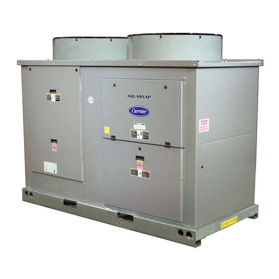
The AquaSnap chiller is an effective all-
in-one package that is easy to install
a30-4827
and easy to own. AquaSnap chillers
operate quietly and efficiently. Value-
added features include:
• Rotary scroll compression
• HFC Puron
• Low-sound AeroAcoustic™ fan
system
• Easy to use ComfortLink™ controls
• Optional integrated hydronic pump
package with VFD (variable frequency
drive) compatible motors
• Microchannel condenser coil
technology
• Accessory fluid storage tank
• Optional digital scroll compressors
Features/Benefits
a30-4826
Carrier's superior chiller
design provides savings at
initial purchase, at installa-
tion, and for years afterward.
Costs less right from the start
Carrier's AquaSnap chillers feature a
compact, all-in-one package design
that installs quickly and easily on the
ground or the rooftop. The optional
pump and hydronic components are
already built in; this costs less than buy-
ing and installing the components indi-
vidually. The chiller's fully integrated
and pre-assembled hydronic system in-
stalls in minutes. No other chiller in
this class installs so easily and inexpen-
sively. The preassembled and integrat-
ed hydronic module utilizes top-quality
components and pumps to ensure
years of reliable operation. Use of the
optional fluid storage tank reduces in-
stallation costs and ensures sufficient
fluid volume is available for close-
coupled and process cooling applica-
tions. The AquaSnap unit's high effi-
ciency keeps costs down.
®
AQUASNAP
10 to 60 Nominal Tons
®
refrigerant (R-410A)
Form 30RAP-5PD
Advertisement
Table of Contents

Related Manuals for Carrier Aquasnap 30RAP010


Summary of Contents for Carrier Aquasnap 30RAP010
-
Page 1: Features/Benefits
Costs less right from the start Carrier’s AquaSnap chillers feature a compact, all-in-one package design that installs quickly and easily on the ground or the rooftop. The optional pump and hydronic components are already built in;... - Page 2 All AquaSnap units are ready to operating ranges, resulting in higher standard scroll compressors. be used with the Carrier Comfort efficiency and improved reliability. Network ® (CCN) system.
- Page 3 Novation Heat Exchanger with design, microchannel coils will reduce Microchannel Coil Technology" catalog average unit operating weight by 25% tions. The Carrier Electronic Catalog (E-Cat) can be used to determine number 04-581042-01 must also be compared to the previous 30RA units.
-
Page 4: Table Of Contents
Model number nomenclature AQUASNAP ® CHILLER MODEL NUMBER DESIGNATION 30RA – Packaging/Security Options 0 – Std Packaging – Air-Cooled AquaSnap Chiller 30RA 4 – Security Grilles/Hail Guards Only 8 – Skid Only D – Skid, Security Grilles/Hail Guards Refrigerant Type J –... -
Page 5: Ahri Capacity Ratings
AHRI* capacity ratings COOLER COOLER FLOW WATER COMPRESSOR TOTAL CAPACITY FULL LOAD IPLV UNIT RATE PRESSURE POWER INPUT POWER POWER 30RAP DROP (kW) (kW) (kW) Tons Ft wg 10.5 36.8 10.7 12.0 10.5 14.5 25.1 13.7 40.9 14.0 49.2 15.6 16.8 10.0 13.1... -
Page 6: Physical Data
Physical data ENGLISH UNIT 30RAP OPERATING WEIGHT (lb) MCHX Condenser Coil, No Pump 1125 1133 1242 1283 2163 2185 2238 2263 2369 2375 MCHX Condenser Coil, Single Pump 1288 1296 1405 1446 2507 2529 2582 2606 2713 2719 MCHX Condenser Coil, Dual Pump 1029 1043 1450... - Page 7 UNIT 30RAP OPERATING WEIGHT (kg) MCHX Condenser Coil, No Pump 1015 1026 1075 1077 MCHX Condenser Coil, Single Pump 1137 1147 1171 1182 1231 1233 MCHX Condenser Coil, Dual Pump 1293 1303 1327 1338 1386 1389 REFRIGERANT TYPE R-410A, EXV Controlled System Total Refrigerant Charge (kg) 13.4 13.6...
- Page 8 Physical data (cont) UNIT WEIGHTS STANDARD UNITS POUNDS KILOGRAMS 30RAP 30RAP Total Total SIZE SIZE Weight Weight 85.5 94.6 73.1 66.1 319.3 87.7 96.4 74.1 67.4 325.5 1125 164.9 119.9 94.9 130.6 510.3 1133 165.8 120.8 95.8 131.5 513.9 1242 178.3 131.8 107.7...
-
Page 9: Options And Accessories
This option also requires field-installed wind baffles. This tions. The Carrier Electronic Catalog (E-Cat) can be used to option is also available as an accessory. This option is a determine whether or not corrosion protection is recom- standard feature on all 30RAP010 and 015 chillers. - Page 10 Options and accessories (cont) Hydronic pump package option adds circulating Remote enhanced display accessory kit contains a pumps, complete with controls, contactor, VFD compati- remotely mounted 40-character per line, 16-line display ble motors, and insulated expansion tank. Available in sin- panel for unit diagnostics.
-
Page 11: Base Unit Dimensions
Base unit dimensions — 30RAP010,015 a30-... - Page 12 Base unit dimensions — 30RAP018-030 a30-5121...
- Page 13 Base unit dimensions — 30RAP035-060 a30-4564 a30-4564...
-
Page 14: Accessory Dimensions
Accessory dimensions a30-4879... - Page 15 a30-4880...
- Page 16 Accessory dimensions (cont) a30-4881...
-
Page 17: Selection Procedure
Selection procedure Carrier’s electronic catalog chiller selection program pro- required), as well as other factors, such as fouling and alti- vides quick, easy selection of Carrier chillers. The program tude correction. considers specific temperature, fluid, flow requirements, To select a 30RAP chiller, including optional pump... -
Page 18: Performance Data
Performance data HEAT EXCHANGER PRESSURE DROP — 30RAP010-030 (ENGLISH) LEGEND 1 — 30RAP010 4 — 30RAP020 2 — 30RAP015 5 — 30RAP025 a30-5122 3 — 30RAP018 6 — 30RAP030 HEAT EXCHANGER PRESSURE DROP — 30RAP035-060 (ENGLISH) 8 9 10 11 & 12 90 100 110 120 130 140 150 160 170 180 190 200 210 220 230 240 250 260 LEGEND 7 —... - Page 19 HEAT EXCHANGER PRESSURE DROP — 30RAP010-030 (SI) LITERS/SECOND LEGEND 1 — 30RAP010 4 — 30RAP020 a30-5124 2 — 30RAP015 5 — 30RAP025 3 — 30RAP018 6 — 30RAP030 HEAT EXCHANGER PRESSURE DROP — 30RAP035-060 (SI) 8 9 10 11 & 12 LITERS/SECOND LEGEND 7 —...
- Page 20 Performance data (cont) UNIT PRESSURE DROP — NO HYDRONIC PACKAGE — 30RAP010-030 (ENGLISH) LEGEND 1 — 30RAP010 4 — 30RAP020 a30-5126 2 — 30RAP015 5 — 30RAP025 3 — 30RAP018 6 — 30RAP030 UNIT PRESSURE DROP — NO HYDRONIC PACKAGE — 30RAP035-060 (ENGLISH) 11 &...
- Page 21 UNIT PRESSURE DROP — NO HYDRONIC PACKAGE — 30RAP010-030 (SI) LITERS/SECOND LEGEND a30-5128 1 — 30RAP010 4 — 30RAP020 2 — 30RAP015 5 — 30RAP025 3 — 30RAP018 6 — 30RAP030 UNIT PRESSURE DROP — NO HYDRONIC PACKAGE — 30RAP035-060 (SI) 8 9 10 11 &...
- Page 22 Performance data (cont) UNIT PRESSURE DROP — SINGLE PUMP HYDRONIC PACKAGE — 30RAP010-030 (ENGLISH) LEGEND 1 — 30RAP010 4 — 30RAP020 a30-5130 2 — 30RAP015 5 — 30RAP025 3 — 30RAP018 6 — 30RAP030 UNIT PRESSURE DROP — SINGLE PUMP HYDRONIC PACKAGE — 30RAP035-060 (ENGLISH) 11 &...
- Page 23 UNIT PRESSURE DROP — SINGLE PUMP HYDRONIC PACKAGE — 30RAP010-030 (SI) LITERS/SECOND LEGEND 1 — 30RAP010 4 — 30RAP020 a30-512 2 — 30RAP015 5 — 30RAP025 3 — 30RAP018 6 — 30RAP030 UNIT PRESSURE DROP — SINGLE PUMP HYDRONIC PACKAGE — 30RAP035-060 (SI) 11 &...
- Page 24 Performance data (cont) UNIT PRESSURE DROP — DUAL PUMP HYDRONIC PACKAGE — 30RAP010-030 (ENGLISH) LEGEND 1 — 30RAP010 4 — 30RAP020 a30-514 2 — 30RAP015 5 — 30RAP025 3 — 30RAP018 6 — 30RAP030 UNIT PRESSURE DROP — DUAL PUMP HYDRONIC PACKAGE — 30RAP035-060 (ENGLISH) 11 &...
- Page 25 UNIT PRESSURE DROP — DUAL PUMP HYDRONIC PACKAGE — 30RAP010-030 (SI) LITERS/SECOND LEGEND 1 — 30RAP010 4 — 30RAP020 a30-516 2 — 30RAP015 5 — 30RAP025 3 — 30RAP018 6 — 30RAP030 UNIT PRESSURE DROP — DUAL PUMP HYDRONIC PACKAGE — 30RAP035-060 (SI) 11 &...
- Page 26 Performance data (cont) PUMP CURVE I FOR HYDRONIC PACKAGE — SINGLE PUMP 1.5 Hp, DUAL PUMP 1.5 Hp, SINGLE PUMP 3.0 Hp, DUAL PUMP 3.0 Hp, SINGLE PUMP HIGH HEAD 3.0 Hp, DUAL PUMP HIGH HEAD 3.0 Hp, HEAD (m) ft 3600 RPM 5.25 in (30.5) 100...
- Page 27 PUMP CURVE II FOR HYDRONIC PACKAGE — SINGLE PUMP 5.0 Hp, DUAL PUMP 5.0 Hp — 30RAP010-030 UNITS HEAD (m) ft 3600 RPM 7.00 in (61.0) 200 6.50 in (48.8) 160 6.00 in 5.50 in (36.6) 120 10 hp 5.00 in 7.5 hp (24.4) 80 5 hp...
- Page 28 Performance data (cont) PUMP CURVE III FOR HYDRONIC PACKAGE — SINGLE PUMP 5.0 Hp, DUAL PUMP 5.0 Hp, SINGLE PUMP HIGH HEAD 5.0 Hp, DUAL PUMP HIGH HEAD 5.0 Hp — 30RAP035-060 UNITS Head (m) ft 3600 RPM 6.19 in (45.7) 150 5.63 in (36.6) 120...
- Page 29 PUMP CURVE IV FOR HYDRONIC PACKAGE — SINGLE PUMP 7.5 Hp, DUAL PUMP 7.5 Hp, SINGLE PUMP 10.0 Hp, DUAL PUMP 10.0 Hp Head (m) ft 3600 RPM 7.00 in (61.0) 200 6.50 in (48.8) 160 6.00 in 20 hp 5.50 in (36.6) 120 15 hp...
- Page 30 Performance data (cont) STORAGE TANK PRESSURE DROP CURVES 100.0 a30-4882 30RAP035-060 10.0 30RAP010-030 1000 ACCESSORY TANK FLOW RATE (gpm) 100.0 a30-4883 30RAP035-060 10.0 30RAP010-030 10.0 ACCESSORY TANK FLOW RATE (L/s)
-
Page 31: Typical Piping And Wiring
3. All wiring must comply with applicable local and national codes. 4. All piping must follow standard piping techniques. Refer to Carrier System Design Manual or appropriate ASHRAE (American Society of Heating, Refrigerating, and Air Conditioning Engineers) handbook for details. - Page 32 3. All wiring must comply with applicable local and national codes. 4. All piping must follow standard piping techniques. Refer to Carrier System Design Manual or appropriate ASHRAE (American Society of Heating, Refrigerating, and Air Conditioning Engineers) handbook for details.
- Page 33 TYPICAL PIPING DIAGRAM ON 30RAP UNITS WITH HYDRONIC PACKAGE LEGEND Factory Supplied 1 — Strainer/Blow-Down Valve 8 — Flow Switch 2 — Expansion Tank 9 — Balance Valve/Drain Plug 3 — Pump 10 — Pressure Relief 4 — Electric Heater 11 —...
-
Page 34: Electrical Data
Electrical data 30RAP ELECTRICAL DATA NO HYDRONIC PACKAGE NO HYDRONIC PACKAGE NO HYDRONIC PACKAGE UNIT VOLTAGE POWER STANDARD LOW-SOUND AEROACOUSTIC™ FAN OPTIONAL VALUE SOUND FANS UNIT SUPPLY Supplied 30RAP V-Hz MOCP Fuse MOCP Fuse REQD. (3 Ph) Size Size 208/230-60 66.1 251.0 66.7... - Page 35 30RAP ELECTRICAL DATA (cont) HYDRONIC PACKAGE WITH STANDARD LOW-SOUND AEROACOUSTIC™ FAN PUMP SIZE 1.5 hp PUMP SIZE 3.0 hp PUMP SIZE 5.0 hp 38RAP UNIT VOLTAGE PUMP OPTIONS "2" OR "9" PUMP OPTIONS "3" OR "4" OR “B” OR “C” PUMP OPTIONS "5"...
- Page 36 Electrical data (cont) 30RAP ELECTRICAL DATA (cont) HYDRONIC PACKAGE WITH STANDARD LOW-SOUND AEROACOUSTIC™ FAN PUMP SIZE 7.5 hp PUMP SIZE 10.0 hp VOLTAGE PUMP OPTIONS "7" OR "G" PUMP OPTIONS "Z" OR "H" 38RAP UNIT SIZE V-Hz (3 Ph) MOCP REC FUSE MOCP REC FUSE...
- Page 37 30RAP ELECTRICAL DATA (cont) HYDRONIC PACKAGE WITH OPTIONAL VALUE SOUND FANS PUMP SIZE 1.5 hp PUMP SIZE 3.0 hp PUMP SIZE 5.0 hp 38RAP UNIT VOLTAGE PUMP OPTIONS "2" OR "9" PUMP OPTIONS "3" OR "4" OR “B” OR “C” PUMP OPTIONS "5"...
- Page 38 Electrical data (cont) 30RAP ELECTRICAL DATA (cont) HYDRONIC PACKAGE WITH OPTIONAL VALUE SOUND FANS PUMP SIZE 7.5 hp PUMP SIZE 10.0 hp VOLTAGE PUMP OPTIONS "7" OR "G" PUMP OPTIONS "Z" OR "H" 38RAP UNIT SIZE V-Hz (3 Ph) MOCP REC FUSE MOCP REC FUSE...
- Page 39 FAN ELECTRICAL DATA FAN ELECTRICAL DATA (Standard Low-Sound AeroAcoustic™ Fans) (Optional Value Sound Fans) STANDARD CONDENSER OPTIONAL CONDENSER FANS FANS UNIT UNIT VOLTAGE UNIT UNIT VOLTAGE 30RAP V-Hz (3 Ph) 30RAP V-Hz (3 Ph) Quantity Quantity (each) (each) 208/230-60 208/230-60 380-60 380-60 460-60...
- Page 40 Electrical data (cont) PUMP ELECTRICAL DATA UNIT VOLTAGE PUMP OPTION PUMP SIZE PUMP RPM V-Hz (3 Ph) (each) 3500 208/230-60 3500 380-60 2, 9 1.5 HP 3500 460-60 3500 575-60 3500 208/230-60 3500 380-60 3, 4, B, C 3.0 HP 3500 460-60 3500...
- Page 41 UNIT INCOMING POWER OPTIONS UNIT INCOMING POWER OPTION Standard Terminal Standard and High SCCR High SCCR Terminal Block Option MOCP VALUE Block Option Terminal Block Option Max. Wire Min. Wire Max. Wire Min. Wire High SCCR Max. Wire Min. Wire Size Size Size...
- Page 42 Electrical data (cont) COMPRESSOR ELECTRICAL DATA CIRCUIT* NUMBER OF UNIT UNIT VOLTAGE COMPRESSORS CIRCUIT A CIRCUIT B 30RAP V-Hz (3 Ph) PER CIRCUIT 208/230-60 48.1 — — 380-60 23.7 — — 460-60 18.6 — — 575-60 14.7 — — 208/230-60 55.8 —...
-
Page 43: Controls
Controls Microprocessor — The ComfortLink™ microprocessor microprocessor uses these inputs to control capacity, the controls overall unit operation. Its central executive routine electronic expansion valve, and fan cycling. controls a number of processes simultaneously. These • Saturated condensing temperature include internal timers, reading inputs, analog to digital •... - Page 44 Troubleshooting literature included with each unit. microprocessor. Packaged service training programs are also available. Contact your Carrier representative for more information. Temperature reset — The energy management module (EMM) is required for 4 to 20 mA reset of LCWT in con- Dual chiller control —...
- Page 45 thermistor for space temperature reset is required. The Configuration settings will be based on any options energy management module (EMM) is only required for or accessories included with the unit at the time of temperature reset that is initiated by a 4 to 20 mA signal. manufacturing.
-
Page 46: Typical Control Wiring Schematic
Typical control wiring schematic a30-5264... -
Page 47: Application Data
Application data Chiller location and clearances capability is desired, chillers may be installed in parallel. Units may be of the same or different sizes with this piping Do not locate near sound sensitive areas without proper arrangement. However, cooler flow rates must be balanced acoustic consideration. - Page 48 Application data (cont) Cooler water temperature NOTE: Recirculation flow is shown below. 1. Maximum leaving chilled water temperature (LCWT) RECIRCULATION FLOW for the unit is 60 F (15.6 C). Unit can start and pull down with up to 95 F (35 C) entering-water tempera- ture.
- Page 49 MINIMUM FLUID VOLUME IN CIRCULATION 30RAP035-060 241 gallons (912 liters) Storage tank weight (water weight included) is as follows: NORMAL AIR PROCESS COOLING OR CONDITIONING LOW AMBIENT OPERATION 30RAP 30RAP010,015 1673 lb (759 kg) APPLICATION APPLICATION UNIT 30RAP018-030 2193 lb (995 kg) gal/ton (L per kW) gal/ton (L per kW) SIZE...
- Page 50 Application data (cont) MINIMUM AND MAXIMUM COOLER FLOW RATES 30RAP MINIMUM COOLER FLOW MAXIMUM COOLER FLOW MINIMUM COOLER FLOW MAXIMUM COOLER FLOW SIZE RATE (gpm) RATE (gpm) RATE (l/s) RATE (l/s) 10.3 11.7 13.2 14.4 15.8 17.0 Select concentration based on either burst or freeze pro- NOTE: In order for a chiller to operate at –20 F (–29 C) tection as dictated by the application.
- Page 51 It is recommended that isolation (shutoff) valves be placed WATER QUALITY CHARACTERISTICS AND LIMITATIONS exterior to the unit to allow removal and service of the entire pump assembly, if necessary. Also, if the unit is iso- WATER CHARACTERISTIC QUALITY LIMITATION lated with valves, a properly sized pressure relief valve Alkalinity (HCO 70 –...
- Page 52 Follow local codes or ASHRAE 90.1 recommendations. 1. Install automatic air vents at all high points in the sys- Contact your Carrier representative for specific amount of tem. (If the 30RAP unit is located at the high point of trim required.
- Page 53 TYPICAL MULTIPLE CHILLER CONFIGURATION WITH AIR ELIMINATOR AND EXPANSION TANK LOCATION DUAL CHILLER LVG SENSOR DISTRIBUTION PUMP EXPANSION TANK(S) AIR ELIMINATOR WITH VENT COLD WATER a30-3652 MAKEUP/FILL SYSTEM...
-
Page 54: Guide Specifications
3. Air shall be discharged vertically upward. Size Range: 10 to 60 Nominal Tons 4. Fans shall be protected by coated steel wire (35 to 210 Nominal kW) safety guards. Carrier Model Number: 30RAP D. Compressor/Compressor Assembly: Part 1 — General 1. Fully hermetic, direct-drive,... - Page 55 Timed maintenance scheduling to signal multiple connection ports for com- maintenance activities for pumps, condenser municating with the local equipment coil cleanings, strainer maintenance and network, the Carrier Comfort Net- user-defined maintenance activities. work ® (CCN) system and access to...
- Page 56 L. Chilled Water Circuit: assistance in amending the specifications, contact 1. Chilled water circuit shall be rated for 300 psig your Carrier representative. (2068 kPa). Units with optional pump package * 1. Low-Ambient Operation: are rated for 150 psig (1034 kPa) working Unit shall be capable of operating down to pressure.
- Page 57 Additional components shall be required and 8. Security Grilles/Hail Guards: used in conjunction with the low ambient Unit shall be supplied with factory or field- device. Components include field-installed wind installed, louvered, sheet metal panels which baffles. If significant low-load operation is antic- securely fasten to the chiller and provide con- ipated, then hot gas bypass is recommended.
- Page 58 Guide specifications (cont) b. Display menus shall provide clear language 19. Ultra-Low Sound: descriptions of all menu items, operating Shall provide an acoustic enclosure around modes, configuration points and alarm each compressor in conjunction with low-sound diagnostics. Reference to factory codes shall aero-acoustic fans to provide significant chiller not be accepted.
- Page 60 For More Information: (866) 787-3271 Sales@PTSdcs.com DATA CENTER SOLUTIONS Carrier Corporation • Syracuse, New York 13221 10-10 Manufacturer reserves the right to discontinue, or change at any time, specifications or designs without notice and without incurring obligations. Book Pg 60 Catalog No.
Need help?
Do you have a question about the Aquasnap 30RAP010 and is the answer not in the manual?
Questions and answers