Table of Contents
Advertisement
Copyright 2009 Carrier Corporation
Product
Data
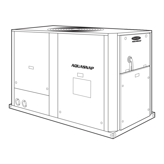
AQUASNAP
30RA010-055
Air-Cooled Chillers
10 to 55 Nominal Tons
(25 to 200 kW)
The AquaSnap chiller is an effective all-
in-one package that is easy to install
and easy to own. AquaSnap chillers
cost less to purchase and install, and
operate quietly and efficiently. Value-
added features include:
• Scroll compression
• Low profile construction
• Quiet AeroAcoustic™ fan system
• Easy to use ComfortLink™ controls
• Integrated hydronic pump package
• Accessory fluid storage tank
Features/Benefits
Carrier's superior chiller
design provides savings at
initial purchase, at installa-
tion, and for years afterward.
Costs less right from the start
Only Carrier's AquaSnap chillers fea-
ture a compact, all-in-one package de-
sign that installs quickly and easily on
the ground or the rooftop. The option-
al pump and hydronic components are
already built in; this costs less than buy-
ing and installing the components indi-
vidually. The chiller's fully integrated
and pre-assembled hydronic system in-
stalls in minutes. No other chiller in
this class installs so easily and inexpen-
sively. The preassembled and integrat-
ed hydronic module utilizes top-quality
components and pumps to ensure
years of reliable operation. Use of the
optional fluid storage tank reduces in-
stallation costs and ensures sufficient
fluid volume is available for close-cou-
pled and process cooling applications.
The AquaSnap unit's high efficiency
keeps costs down.
®
Form 30RA-5PD
Advertisement
Table of Contents

Related Manuals for Carrier AQUASNAP 30RA010-055


Summary of Contents for Carrier AQUASNAP 30RA010-055
-
Page 1: Features/Benefits
Costs less right from the start Only Carrier’s AquaSnap chillers fea- ture a compact, all-in-one package de- sign that installs quickly and easily on the ground or the rooftop. The option- al pump and hydronic components are already built in;... - Page 2 The fan is mounted to an extremely All AquaSnap units are ready to ComfortLink controls speak rigid tower, which further reduces be used with the Carrier Comfort your language vibrations and noise by preventing Network ® (CCN) system.
-
Page 3: Table Of Contents
AEROACOUSTIC™ FAN vs. PROPELLER FAN MODE Run Status Service Test Temperature Pressures Setpoints Inputs Alarm Status Outputs ESCAPE ENTER Configuration PENETRATES BUILDING Time Clock STRUCTURE Operating Modes Alarms 1080 1600 2400 4000 6300 8000 1/3 OCTAVE BAND CENTER FREQUENCY (Hz) SCROLLING MARQUEE DISPLAY AEROACOUSTIC FAN PROPELLER FAN... -
Page 4: Model Number Nomenclature
Model number nomenclature AQUASNAP ® CHILLER MODEL NUMBER DESIGNATION – – – – – Factory-Installed Options (FIOP) 38RA – Air-Cooled AquaSnap Chiller Compressor Start Option N – Standard Across-the-Line Start Packaging 1 – Standard Domestic (Coil Cover and Unit Sizes Bottom Skid) 010 025 3 –... -
Page 5: Physical Data
Physical data ENGLISH UNIT 30RA REFRIGERANT TYPE R-22, TXV Controlled System Refrigerant Charge (lb) Ckt A/Ckt B 16/— 24/— 31/— 40/— 45/— 55/— 44/30 45/30 44/44 45/45 55/55 COMPRESSORS Scroll, Hermetic Quantity Speed (Rpm) 3500 (Qty) Ckt A (1) SM115, (1) SM115, (1) SM125, (1) SM125... - Page 6 Physical data (cont) UNIT WEIGHTS STD UNITS POUNDS — ALUMINUM POUNDS — COPPER 30RA 30RA Total Total SIZE SIZE Weight Weight 1025 1068 1199 1209 1338 1523 1713 1589 1780 1705 1930 2844 3224 2914 3294 3218 1011 3599 3313 1051 3693 3515...
- Page 7 UNIT WEIGHTS (cont) DUAL PUMP UNITS POUNDS — ALUMINUM POUNDS — COPPER 30RA 30RA Total Total SIZE SIZE Weight Weight 1176 1255 1298 1429 1439 1568 1753 1943 1819 2010 1935 2160 3134 1044 3514 3204 1079 3584 3508 1043 1092 3889 1029...
-
Page 8: Options And Accessories
Options and accessories FACTORY-INSTALLED FIELD-INSTALLED ITEM OPTION ACCESSORY Hydronic Pump Package Enviro-Shield™ System Condenser Coil Protection Options Copper Fins Aluminum Fins, E-coat Copper Fins, E-coat Aluminum Fins, Pre-coated Medium Temperature Brine, 15 F to 40 F LBT Non-Fused Disconnect Low-Ambient Protection Package (Cooler Heater) Motormaster®... - Page 9 Field-installed accessories complete liquid line shutoff when the chiller is shut down. This accessory is required when the medium temperature Minimum load control — This option allows additional brine option or the Motormaster V are used. capacity reduction for unit operation below the minimum step of unloading (down to 15% of the minimum unit Wind baffle kit —...
-
Page 10: Dimensions
Dimensions — 30RA010,015,018 a30-4597... - Page 11 Dimensions — 30RA022,025 a30-4598...
- Page 12 Dimensions — 30RA030 a30-4599...
- Page 13 Dimensions — 30RA035,040...
- Page 14 Dimensions — 30RA045,050 a30-4601...
- Page 15 Dimensions — 30RA055 a30-4602...
- Page 16 Dimensions — storage tank 30RA010-018 a30-4603...
- Page 17 Dimensions — storage tank 30RA022-030 a30-4604...
-
Page 18: Dimensions
Dimensions — storage tank 30RA035-055 a30-4605... -
Page 19: Selection Procedure
Selection procedure Carrier’s electronic catalog chiller selection program pro- SI EXAMPLE vides quick, easy selection of Carrier chillers. The program I Determine unit size and operating conditions considers specific temperature, fluid, and flow require- required to meet given capacity at given ments and other factors, such as fouling and altitude conditions. - Page 20 PROPYLENE % GLYCOL ments. A dual pump option is also available for primary/ GLYCOL GLYCOL standby operation. The Carrier E-Cat Packaged AC Chiller 0 (Pure Water) Builder can be used for pump selection, or selection can be 1.062 1.077 done manually.
- Page 21 PUMP CURVE FOR HYDRONIC PACKAGE OPTIONS A, C, F, AND H (1.5-2.0 Hp) PUMP CURVE FOR HYDRONIC PACKAGE OPTIONS B, D, G, AND J (2-3 Hp) PUMP CURVE FOR HYDRONIC PACKAGE OPTIONS E AND K (5.0 Hp) NPSH — Net Postive Suction Head...
- Page 22 Selection procedure (cont) PRESSURE DROP, WITHOUT PUMP UNITS, PRESSURE DROP, WITHOUT PUMP UNITS, 30RA010-030 (English) 30RA010-030 (SI) PRESSURE DROP, WITHOUT PUMP UNITS, PRESSURE DROP, WITHOUT PUMP UNITS, 30RA035-055 (English) 30RA035-055 (SI) PRESSURE DROP, SINGLE PUMP UNITS, PRESSURE DROP, SINGLE PUMP UNITS, 30RA010-030 (SI) 30RA010-030 (English) Use the following formula to convert psig to feet of water:...
- Page 23 PRESSURE DROP, SINGLE PUMP UNITS, PRESSURE DROP, SINGLE PUMP UNITS, 30RA035-055 (English) 30RA035-055 (SI) PRESSURE DROP, DUAL PUMP UNITS, PRESSURE DROP, DUAL PUMP UNITS, SIZES 30RA010-030 (SI) SIZES 30RA010-030 (English) PRESSURE DROP, DUAL PUMP UNITS, PRESSURE DROP, DUAL PUMP UNITS, SIZES 30RA035-055 (English) SIZES 30RA035-055 (SI) Use the following formula to convert psig to feet of water:...
- Page 24 Selection procedure (cont) STORAGE TANK PRESSURE DROP CURVES 100.0 30RA-900---010 10.0 30RA-900---001,009 1000 ACCESSORY TANK FLOW RATE (gpm) 100.0 30RA-900---010 10.0 30RA-900---001,009 10.0 ACCESSORY TANK FLOW RATE (L/s)
- Page 25 30RA010-030 PUMP ENVELOPES 30RA035-055 PUMP ENVELOPES NOTES: 1. Refer to Position 9 in the unit’s model number for pump identification. 2. To convert gpm to L/s, multiply by 0.063. To convert head pressure to kPa, multiply by 2.986. Expansion tank selection and filling If the top of the piping system (the highest point in the hydronic piping) is more than 80 ft (12.2 m) above the Expansion tanks are essential to the operation of any...
-
Page 26: Performance Data
Performance data PACKAGED AIR-COOLED CHILLER RATINGS TABLE — ENGLISH CONDENSER ENTERING AIR TEMPERATURE (F) LCWT UNIT Cooler Cooler Cooler Cooler Cooler SIZE Cap. Input Cap. Input Cap. Input Cap. Input Cap. Input Flow Rate Flow Rate Flow Rate Flow Rate Flow Rate (Tons) (Tons) - Page 27 PACKAGED AIR-COOLED CHILLER RATINGS TABLE — SI CONDENSER ENTERING AIR TEMPERATURE (C) LCWT UNIT Cooler Cooler Cooler Cooler Cooler SIZE Cap. Input Cap. Input Cap. Input Cap. Input Cap. Input Flow Rate Flow Rate Flow Rate Flow Rate Flow Rate (kW) (kW) (kW)
-
Page 28: Typical Piping And Wiring
3. All wiring must comply with applicable local and national codes. 4. All piping must follow standard piping techniques. Refer to Carrier System Design Manual or appropriate ASHRAE (American Society of Heating, Refrigeration, and Air Conditioning Engineers) handbook for details. - Page 29 TYPICAL PIPING DIAGRAM ON 30RA UNITS WITH HYDRONIC PACKAGE LEGEND Factory Supplied 1 — Strainer/Blow-Down Valve 8 — Flow Switch 2 — Expansion Tank 9 — Balance Valve/Drain Plug 3 — Pump 10 — Pressure Relief 4 — Electric Heater 11 —...
-
Page 30: Electrical Data
Electrical data 30RA ELECTRICAL DATA 2.0/1.5 HP 2.0/1.5 HP 1.5/1.0 HP PUMP 3.0/2.0 HP PUMP 5.0/3.0 HP PUMP (STD) PUMP (ALT) PUMP UNIT VOLTAGE NO HYDRONIC PACKAGE Pump Options Pump Options Pump Options POWER Pump Options Pump Options ‘A’ or ‘F’ ‘D’... - Page 31 FAN ELECTRICAL DATA PUMP ELECTRICAL DATA UNIT VOLTAGE STANDARD CONDENSER FANS UNIT VOLTAGE PUMP PUMP PUMP UNIT OPTION SIZE (each) (each) Circuit A Circuit B V-Hz (3 Ph) 30RA V-Hz (3 Ph) Quantity (each) Quantity (each) 3500 230-60 32.0 230-60 —...
- Page 32 Electrical data (cont) COMPRESSOR ELECTRICAL DATA UNIT VOLTAGE COMPRESSOR UNIT 30RA V-Hz (3 Ph) 230-60 30.9 — — — — — — 208/230-60 34.3 — — — — — — 460-60 16.0 — — — — — — 575-60 12.9 —...
-
Page 33: Controls
Controls Microprocessor — The ComfortLink™ microprocessor Two refrigerant pressure transducers are used in each controls overall unit operation. Its central executive routine circuit for sensing suction and discharge pressure. The controls a number of processes simultaneously. These microprocessor uses these inputs to control capacity and include internal timers, reading inputs, analog to digital fan cycling. -
Page 34: Controls
Controls (cont) Standard ComfortLink™ controls with scrolling space temperature reset selected. energy marquee display module — A four-digit alphanumeric management module (EMM) is only required for tempera- display shows all of the ComfortLink control codes (with ture reset that is initiated by a 4 to 20 mA signal. 60-character expandable clear language), plus set points, Demand limit —... -
Page 35: Typical Control Wiring Schematic
Typical control wiring schematic (30RA010-030) LEGEND — Alarm — American Wire Gage — Chilled Water Pump CWPI — Chilled Water Pump Interlock — Energy Management Module GFI-CO — Ground Fault Interrupt Convenience Outlet FIOP — Factory-Installed Option — National Electric Code —... - Page 36 Typical control wiring schematic (30RA035-055) NOTES: FACTORY WIRING IS IN ACCORDANCE WITH NATIONAL ELECTRICAL CODE (NEC). FIELD MODIFICA- TIONS OR ADDITIONS MUST BE IN COMPLIANCE WITH ALL APPLICABLE CODES. WIRING FOR MAIN FIELD SUPPLY MUST BE RATED 75C MINIMUM. USE COPPER FOR ALL UNITS. MAXI- MUM INCOMING WIRE SIZE FOR THE TERMINAL BLOCK IS 350 KCMIL.
-
Page 37: Typical Control Wiring Schematic
Typical control wiring schematic (storage tank) -
Page 38: Application Data
Application data Chiller location 1. Multiple smaller chillers may be applied in series, each providing a portion of the design temperature rise. Do not locate near sound sensitive areas without proper acoustic consideration. Pad isolated from building rooftop 2. Cooler fluid may be recirculated to raise the flow rate mounting requires consideration for structure-borne trans- to the chiller. - Page 39 Variable cooler flow rates Tank volume Variable rates may be applied to standard chiller. Unit will, A properly baffled storage tank is available as an accessory. however, attempt to maintain a constant leaving chilled These tanks are designed to physically fit beneath the fluid temperature.
- Page 40 Application data (cont) 4. Use a feeder/transfer pump to mix the solution and fill the system. Circulate the cleaning system for the TYPICAL DUAL PUMP PACKAGE length of time recommended by the cleaning agent manufacturer. a. After cleaning, drain the cleaning fluid and flush the system with fresh water.
- Page 41 Cooler fouling factor concentration will be high enough to keep the fluid in a condition that it can be pumped at low ambient conditions. The fouling factor used to calculate tabulated ratings was ⋅ hr ⋅ °F/Btu (0.000018 m ⋅ °C/W). As foul- 0.00010 ft IMPORTANT: Glycol anti-freeze solutions are highly ing factor is increased, unit capacity decreases and com-...
- Page 42 Application data (cont) Multiple chillers are completely encapsulated from environmental contami- nation. Specify e-coated aluminum-fin coils for industrial Where chiller capacities greater than 55 tons (180 kW) are environments with high levels of air pollution. This option required, or where standby capability is desired, chillers also provides better protection compared to standard or may be installed in parallel.
- Page 43 Gener- ommended to reduce energy consumption. Contact your ally speaking, this is the best place to install an air separa- Carrier representative for specific amount of trim required. tor, if possible. Expansion tank supplied will allow loop expansion due 1.
-
Page 44: Guide Specifications
Size Range: 10 to 55 Nominal Tons D. Compressors: (25 to 200 Nominal kW) 1. Fully hermetic scroll type compressors. Carrier Model Number: 30RA 2. Direct drive, 3500 rpm, protected by line break Part 1 — General device, suction gas cooled motor. - Page 45 Chilled water pump start/stop control and municating with the local equipment primary/standby sequencing to ensure equal network, the Carrier Comfort Net- pump run time. work ® (CCN) system and the ability to access all chiller control functions g.
- Page 46 L. Chilled Water Circuit: tance in amending the specifications, contact your 1. Chilled water circuit shall be rated for 300 psig Carrier representative. (2068 kPa). Units with optional pump package * 1. Low-Ambient Operation: are rated for 150 psig (1034 kPa) working Unit shall be capable of operating down to pressure.
- Page 47 without material bridging between fins. 7. Medium Temperature Brine: Coating process shall ensure complete coil Unit shall be factory modified to start and oper- encapsulation. Color shall be high gloss ate at leaving chilled fluid temperatures between black with gloss — 60° of 65 to 90% per 15 F (–9 C) and 40 F (4.4 C).
-
Page 48: Guide Specifications
Display menus shall provide clear language descriptions of all menu items, operating modes, configuration points and alarm Carrier Corporation • Syracuse, New York 13221 6-09 Manufacturer reserves the right to discontinue, or change at any time, specifications or designs without notice and without incurring obligations.
Need help?
Do you have a question about the AQUASNAP 30RA010-055 and is the answer not in the manual?
Questions and answers