Carrier AquaSnap 30RAP010-150 Installation Instructions Manual
Liquid chillers with puron refrigerant r-410a
Hide thumbs
Also See for AquaSnap 30RAP010-150:
- Controls, start-up, operation, service, and troubleshooting (141 pages) ,
- Start up & operation manual (132 pages) ,
- Installation instructions manual (12 pages)
Table of Contents
Advertisement
CONTENTS
SAFETY CONSIDERATIONS . . . . . . . . . . . . . . . . . . . . .1,2
INSTALLATION . . . . . . . . . . . . . . . . . . . . . . . . . . . . . . . . 2-57
Storage . . . . . . . . . . . . . . . . . . . . . . . . . . . . . . . . . . . . . . . . . . 2
Step 1 - Place and Rig the Unit. . . . . . . . . . . . . . . . . . 2
• RIGGING
Step 2 - Check Compressor Mounting . . . . . . . . . 11
Connections . . . . . . . . . . . . . . . . . . . . . . . . . . . . . . . . . . 11
Step 4 - Fill the Chilled Water Loop . . . . . . . . . . . . 25
Step 5 - Make Electrical Connections . . . . . . . . . . 35
• POWER WIRING
Step 6 - Install Accessories . . . . . . . . . . . . . . . . . . . . 53
• ELECTRICAL
Step 7 - Check Refrigerant Circuit . . . . . . . . . . . . . 53
• LEAK TESTING
• DEHYDRATION
BACnet Communication Option Wiring. . . . . . . . . . 55
APPENDIX A (Pressure Drop Curves) . . . . . . . . 58-70
SAFETY CONSIDERATIONS
Installing, starting up, and servicing air-conditioning equip-
ment can be hazardous due to system pressures, electrical
components, and equipment location (roofs, elevated struc-
tures, etc.).
Only trained, qualified installers and service mechanics
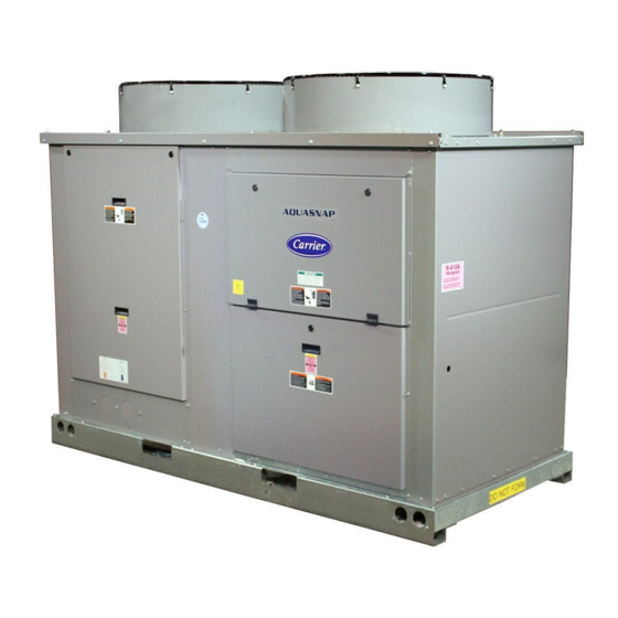
should install, start up, and service this equipment (Fig. 1).
Untrained personnel can perform basic maintenance func-
tions such as cleaning coils. All other operations should be
performed by trained service personnel.
When working on the equipment, observe precautions in the
literature and on tags, stickers, and labels attached to the
equipment.
• Follow all safety codes.
• Wear safety glasses and work gloves.
• Keep quenching cloth and fire extinguisher nearby when
brazing.
• Use care in handling, rigging, and setting bulky
equipment.
Catalog No. 04-53300131-01
Installation Instructions
Page
Printed in U.S.A.
®
with Puron
Refrigerant (R-410A)
Fig. 1 - Typical 30RAP Unit (018-030 Shown)
.
Electrical shock can cause personal injury and death. Shut
off all power to this equipment during installation. There
may be more than one disconnect switch. Tag all discon-
nect locations to alert others not to restore power until work
is completed.
DO NOT USE TORCH to remove any component. System
contains oil and refrigerant under pressure.
To remove a component, wear protective gloves and gog-
gles and proceed as follows:
a. Shut off electrical power to unit.
b. Recover refrigerant to relieve all pressure from sys-
tem using both high-pressure and low pressure ports.
c. Traces of vapor should be displaced with nitrogen
and the work area should be well ventilated. Refrig-
erant in contact with an open flame produces toxic
gases.
d. Cut component connection tubing with tubing cutter
and remove component from unit. Use a pan to catch
any oil that may come out of the lines and as a gage
for how much oil to add to the system.
e. Carefully unsweat remaining tubing stubs when nec-
essary. Oil can ignite when exposed to torch flame.
Failure to follow these procedures may result in personal
injury or death.
Form 30RAP-12SI
Pg 1
AquaSnap
30RAP010-150
Liquid Chillers
WARNING
WARNING
3-14
Replaces: 30RAP-11SI
®
Advertisement
Table of Contents

Subscribe to Our Youtube Channel
Related Manuals for Carrier AquaSnap 30RAP010-150


Summary of Contents for Carrier AquaSnap 30RAP010-150
-
Page 1: Table Of Contents
® AquaSnap 30RAP010-150 Liquid Chillers ® with Puron Refrigerant (R-410A) Installation Instructions CONTENTS Page SAFETY CONSIDERATIONS .....1,2 INSTALLATION ....... . 2-57 Storage . -
Page 2: Installation
For 30RAP070-150, see Fig. 3. When chillers are arranged in parallel, a minimum of 10 ft (3048 mm) between chillers is CAUTION recommended. Acceptable clearance on the cooler connection side or end opposite the control box of the unit can be reduced DO NOT re-use compressor oil or any oil that has been to 3 ft (1 m) without sacrificing performance as long as the re- exposed to the atmosphere. - Page 3 30RA Packaging/Security Options 0 – Std Packaging – Air-Cooled AquaSnap Chiller 30RA 4 – Security Grilles/Hail Guards Only 8 – Skid Only D – Skid, Security Grilles/Hail Guards Refrigerant Type J – Skid, Top Crate, Bag ® P – Puron N –...
- Page 4 MCHX STANDARD UNITS WEIGHT AT MOUNTING POINTS (POUNDS) WEIGHT AT MOUNTING POINTS (KILOGRAMS) 30RAP 30RAP Total Total SIZE SIZE Weight Weight — — — — — — — — — — 1125 — — — — 1133 — — — —...
- Page 5 AL/CU COIL NO PUMP UNITS WEIGHT AT MOUNTING POINTS (POUNDS) WEIGHT AT MOUNTING POINTS (KILOGRAMS) 30RAP 30RAP Total Total SIZE SIZE Weight Weight 1017 1030 — — 3759 — — 1705 — — — — 1062 1100 4064 1843 — —...
- Page 6 CU/CU COIL NO PUMP UNITS WEIGHT AT MOUNTING POINTS (POUNDS) WEIGHT AT MOUNTING POINTS (KILOGRAMS) 30RAP 30RAP Total Total SIZE SIZE Weight Weight 1179 1194 — — 4359 — — 1977 — — — — 1250 1294 1140 1100 4784 2170 —...
- Page 7 Table 1A — Physical Data, 30RAP — English UNIT 30RAP OPERATING WEIGHT (lb)* MCHX Condenser Coil, No Pump 1125 1133 1242 1283 2163 2185 2238 2263 MCHX Condenser Coil, Single Pump 1288 1296 1405 1446 2507 2529 2582 2606 MCHX Condenser Coil, Dual Pump 1029 1043 1450...
- Page 8 Table 1A — Physical Data, 30RAP — English (cont) UNIT 30RAP OPERATING WEIGHT (lb)* MCHX Condenser Coil, No Pump 2369 2375 3410 3641 3697 4690 5008 6451 6938 MCHX Condenser Coil, Single Pump 2713 2719 3812 4035 4061 5089 5407 6850 7337 MCHX Condenser Coil, Dual Pump...
- Page 9 Table 1B — Physical Data, 30RAP — SI UNIT 30RAP OPERATING WEIGHT (kg)* MCHX Condenser Coil, No Pump 1015 1026 MCHX Condenser Coil, Single Pump 1137 1147 1171 1182 MCHX Condenser Coil, Dual Pump 1293 1303 1327 1338 REFRIGERANT TYPE R-410A, EXV Controlled System Total Refrigerant Charge (kg) 13.4...
- Page 10 Table 1B — Physical Data, 30RAP — SI (cont) UNIT 30RAP OPERATING WEIGHT (kg)* MCHX Condenser Coil, No Pump 1075 1077 1547 1652 1677 2127 2272 2926 3147 MCHX Condenser Coil, Single Pump 1231 1233 1729 1830 1842 2308 2453 3107 3328 MCHX Condenser Coil, Dual Pump...
-
Page 11: Mounting Unit
Do not circulate water through unit without strainer in ment specialist or appropriate literature for information regard- place. Failure to use the strainer represents abuse and may ing filtration, water treatment, and control devices. impair or otherwise negatively affect the Carrier product warranty. - Page 12 a30-4916 Fig. 9A — Unit Rigging Label Detail (010-060 Sizes)
- Page 13 CAUTION - NOTICE TO RIGGERS: ALL PANELS MUST BE IN PLACE WHEN RIGGING. DO NOT FORK THIS UNIT WITHOUT SKID. NOTES: RIG WITH FOUR CABLES USING A MINIMUM 24 FT. (7315MM) LENGTH FOR 070-115 SIZES. RIG WITH SIX CABLES FOR 130, 150TON. CENTRAL LIFTING POINTS MUST BE A MINIMUM OF 12 FT.
- Page 14 a30-5733...
- Page 15 a30-5734...
- Page 16 a30-5735...
- Page 17 a30-5731...
- Page 18 a30-5730...
- Page 19 a30-5732...
- Page 20 a30-5429...
- Page 21 a30-5430...
- Page 22 a30-5431...
-
Page 23: Units With Factory-Installed Hydronic Packages
UNITS WITH FACTORY-INSTALLED HYDRONIC the piping between the unit and the valves, following all PACKAGES — The 30RAP chillers with factory-installed applicable state and local codes. hydronic packages are designed for use with closed systems, System Pressurization — A proper initial cold fill pressure meaning that there is no more than one water-air interface in must be established before the filling of the unit. -
Page 24: Air Separation
tanks) in a system (unless manifolded together). If system volume or other design considerations warrant the placement of another expansion tank somewhere in the system, the expan- sion tank in the 30RAP hydronic package MUST be discon- nected from its hose and the end of the hose securely plugged. This is also true for applications where two or more 30RAP chillers are placed in parallel. -
Page 25: Air Separation
Circulate the cleaning system for the length of time recommended by the cleaning agent manufacturer. Carrier’s ComfortLink controls provided have a built-in feature to remind building owners or operators to clean the a. After cleaning, drain the cleaning fluid and flush the strainer by discharging the blow-down valve at a pre-set time system with fresh water. - Page 26 Fig. 22 — Typical Set Up for Cleaning Process 3. The gpm corresponding to the pressure drop measured is the flow through the balancing valve. NOTE: Carrier recommends a differential pressure gage when SYSTEM measuring pressures across the pumps or balancing valves.
- Page 27 Table 4 — Balancing Valve Readings — 30RAP010-030 WATER PRESSURE DROP (ft) VALVE 2.0 in. COEFFICIENT SETTING 13.4 21.0 30.2 41.1 53.7 67.9 83.8 10.2 13.9 20.0 27.2 35.5 45.0 55.5 13.0 12.3 16.7 21.9 27.7 34.2 16.9 12.9 16.4 20.2 20.5 11.1...
- Page 28 Table 6 — Balancing Valve Readings — 30RAP070-090 WATER PRESSURE DROP (ft) 3.0 in. VALVE STRAIGHT COEFFICIENT SETTING 20.0 28.3 37.0 46.8 57.8 69.9 83.2 97.6 113.2 129.9 147.8 166.9 187.1 208.5 22.9 21.6 28.2 35.7 44.0 53.3 63.4 74.4 86.3 99.1 112.8...
- Page 29 Table 7 — Balancing Valve Readings — 30RAP100-150 WATER PRESSURE DROP (ft) 4.0 in. VALVE STRAIGHT COEFFICIENT SETTING 21.5 32.0 40.5 50.0 60.5 72.0 84.5 97.9 112.4 127.9 144.4 161.9 180.4 199.9 25.0 23.7 29.9 37.0 44.7 53.2 62.5 72.4 83.2 94.6 106.8...
- Page 30 LEGEND a30-4919 1 — 30RAP010 4 — 30RAP020 2 — 30RAP015 5 — 30RAP025 3 — 30RAP018 6 — 30RAP030 Fig. 24 — Heat Exchanger Pressure Drop (Water Only) — 30RAP010-030 (English) 11 & 12 LEGEND a30-4920 7 — 30RAP035 10 —...
- Page 31 a30-5350 LEGEND 1 — 30RAP070 2 — 30RAP080 3 — 30RAP090 Fig. 26 — Heat Exchanger Pressure Drop (Water Only) — 30RAP070-090 (English) a30-5444 LEGEND 1 — 30RAP100 2 — 30RAP115 3 — 30RAP130 4 — 30RAP150 Fig. 27 — Heat Exchanger Pressure Drop (Water Only) — 30RAP100-150 (English)
- Page 32 LEGEND LITERS/SECOND 1 — 30RAP010 4 — 30RAP020 a30-4921 2 — 30RAP015 5 — 30RAP025 3 — 30RAP018 6 — 30RAP030 Fig. 28 — Heat Exchanger Pressure Drop (Water Only) — 30RAP010-030 (SI) 11 & 12 LITERS/SECONDS LEGEND a30-4922 7 — 30RAP035 10 —...
- Page 33 a30-5351 LEGEND 1 — 30RAP070 2 — 30RAP080 3 — 30RAP090 LITERS/SECOND Fig. 30 — Heat Exchanger Pressure Drop (Water Only) — 30RAP070-090 (SI) a30-5445 LEGEND 1 — 30RAP100 2 — 30RAP115 3 — 30RAP130 4 — 30RAP150 LITERS/SECOND Fig. 31 — Heat Exchanger Pressure Drop (Water Only) — 30RAP100-150 (SI)
- Page 34 VFD. When applied with a VFD, the maximum length of wiring between the drive and the pump GOOD motor is 50 ft (15.2 m). The maximum allowable carrier fre- Fig. 32 — Tank Baffling quency of the inverter is 12 kHz, with 3 kHz recommended.
-
Page 35: Preparation For Year-Round Operation
Failure to use the strainer represents abuse and may impair 1. The control circuit does NOT require a separate power or otherwise negatively affect the Carrier product warranty. source. Control circuit power is obtained by a step-down transformer from the main three-phase power supply. The 1. -
Page 36: Power Supply
3. Power entry is at the right-hand side of the unit when fac- 5. Terminals for field power supply are suitable for ing the control box. copper conductors. Insulation must be rated 167 F (75 C) minimum. 4. Maximum field wire sizes allowed by lugs on terminal block/non-fused disconnect are listed in Table 12. -
Page 37: Power Supply
Table 13 — 30RAP Electrical Data — Single Point, No Hydronic Package NO HYDRONIC PACKAGE NO HYDRONIC PACKAGE UNIT VOLTAGE POWER STANDARD LOW-SOUND AEROACOUSTIC™ FAN OPTIONAL VALUE SOUND FANS UNIT SUPPLY Supplied 30RAP V-Hz MOCP Fuse MOCP Fuse REQD. (3 Ph) Size Size 208/230-60... -
Page 38: Power Supply
Table 14 — 30RAP Electrical Data — Dual Point, Low Sound AeroAcoustic™ Fan, No Hydronic Package UNIT VOLTAGE CIRCUIT 1 CIRCUIT 2 UNIT Supplied V-Hz Rec Fuse Rec Fuse 30RAP MOCP MOCP (3 Ph) Size Size 208/230-3-60 155.6 425.8 181.4 451.6 380-3-60 96.0... -
Page 39: Power Supply
Table 15 — 30RAP Electrical Data — Dual Point, Optional Value Sound Fan, No Hydronic Package UNIT VOLTAGE CIRCUIT 1 CIRCUIT 2 UNIT Supplied V-Hz 30RAP MOCP Fuse MOCP Fuse (3 Ph) Size Size 208/230-3-60 158.6 428.8 181.4 451.6 380-3-60 96.0 249.5 110.5... -
Page 40: Power Supply
Table 16 — 30RAP Electrical Data — Single Point, Hydronic Package with Standard Low-Sound AeroAcoustic™ Fan PUMP SIZE 1.5 hp PUMP SIZE 3.0 hp PUMP SIZE 5.0 hp 38RAP UNIT VOLTAGE SIZE V-Hz (3 Ph) MOCP REC FUSE MOCP REC FUSE MOCP REC FUSE 208/230-60... -
Page 41: Power Supply
Table 16 — 30RAP Electrical Data — Single Point, Hydronic Package with Standard Low-Sound AeroAcoustic™ Fan (cont) PUMP SIZE 7.5 hp PUMP SIZE 10.0 hp PUMP SIZE 15.0 hp VOLTAGE 38RAP UNIT SIZE V-Hz (3 Ph) MOCP REC FUSE MOCP REC FUSE MOCP REC FUSE... - Page 42 Table 17 — 30RAP Electrical Data — Dual Point, Hydronic Package with Standard Low-Sound AeroAcoustic™ Fan PUMP SIZE 3.0 hp PUMP SIZE 3.0 hp 38RAP UNIT VOLTAGE CIRCUIT 1 CIRCUIT 2 SIZE V-Hz (3 Ph) MOCP REC FUSE MOCP REC FUSE 208/230-3-60 155.6 425.8...
-
Page 43: Power Supply
Table 17 — 30RAP Electrical Data — Dual Point, Hydronic Package with Standard Low-Sound AeroAcoustic™ Fan (cont) PUMP SIZE 10.0 hp PUMP SIZE 10.0 hp 38RAP UNIT VOLTAGE CIRCUIT 1 CIRCUIT 2 SIZE V-Hz (3 Ph) MOCP REC FUSE MOCP REC FUSE 208/230-3-60 155.6... -
Page 44: Power Supply
Table 18 — 30RAP Electrical Data — Single Point, Hydronic Package with Optional Value Sound Fans PUMP SIZE 1.5 hp PUMP SIZE 3.0 hp PUMP SIZE 5.0 hp 38RAP UNIT VOLTAGE SIZE V-Hz (3 Ph) MOCP REC FUSE MOCP REC FUSE MOCP REC FUSE 208/230-60... -
Page 45: Power Supply
Table 18 — 30RAP Electrical Data — Single Point, Hydronic Package with Optional Value Sound Fans (cont) PUMP SIZE 7.5 hp PUMP SIZE 10.0 hp PUMP SIZE 15.0 hp 38RAP UNIT VOLTAGE SIZE V-Hz (3 Ph) MOCP REC FUSE MOCP REC FUSE MOCP REC FUSE... - Page 46 Table 19 — 30RAP Electrical Data — Dual Point, Hydronic Package with Optional Value Sound Fans PUMP SIZE 3.0 hp PUMP SIZE 3.0 hp 38RAP UNIT VOLTAGE CIRCUIT 1 CIRCUIT 2 SIZE V-Hz (3 Ph) MOCP REC FUSE MOCP REC FUSE 208/230-3-60 158.6 428.8...
-
Page 47: Power Supply
Table 19 — 30RAP Electrical Data — Dual Point, Hydronic Package with Optional Value Sound Fans (cont) PUMP SIZE 10.0 hp PUMP SIZE 10.0 hp 38RAP UNIT VOLTAGE CIRCUIT 1 CIRCUIT 2 SIZE V-Hz (3 Ph) MOCP REC FUSE MOCP REC FUSE 208/230-3-60 158.6... -
Page 48: Power Supply
Table 20A — Fan Electrical Data — Table 20B — Fan Electrical Data — Single Point, Standard Single Point, Standard Low-Sound AeroAcoustic™ Fans Low-Sound AeroAcoustic™ Fans Unit Sizes 010-060 Unit Sizes 070-150 STANDARD CONDENSER STANDARD CONDENSER FANS FANS UNIT UNIT VOLTAGE UNIT UNIT VOLTAGE 30RAP... -
Page 49: Power Supply
Table 21A — Fan Electrical Data — Table 21B — Fan Electrical Data — Single Point, Optional Value Sound Fans Single Point, Optional Value Sound Fans Unit Sizes 010-060 Unit Sizes 070-150 OPTIONAL CONDENSER FANS OPTIONAL CONDENSER FANS UNIT UNIT VOLTAGE UNIT UNIT VOLTAGE 30RAP... -
Page 50: Power Supply
Table 22 — Pump Electrical Data 30RAP SIZE PUMP OPTION PUMP SIZE PUMP RPM UNIT VOLTAGE V-Hz (3 Ph) FLA (each) 3500 208/230-60 3500 380-60 2, 9 1.5 HP 3500 460-60 3500 575-60 3500 208/230-60 3500 380-60 3, 4, B, C 3.0 HP 3500 460-60... - Page 51 Table 24A — Compressor Electrical Data, Unit Sizes 010-060 CIRCUIT* NUMBER OF UNIT UNIT VOLTAGE COMPRESSORS CIRCUIT A CIRCUIT B 30RAP V-Hz (3 Ph) PER CIRCUIT 208/230-60 48.1 — — 380-60 23.7 — — 460-60 18.6 — — 575-60 14.7 —...
- Page 52 Table 24B — Compressor Electrical Data, Unit Sizes 070-150 CIRCUIT* NUMBER OF UNIT UNIT VOLTAGE COMPRESSORS CIRCUIT A CIRCUIT B 30RAP V-Hz (3 Ph) PER CIRCUIT 208/230-60 55.8 55.8 380-60 34.0 34.0 380/415-50 26.9 26.9 460-60 26.9 26.9 575-60 23.7 23.7 208/230-60 51.3...
-
Page 53: Field Connections
Minimum Load Accessory — If minimum load accessory is corner post to locate the center of the field power entry. To required, refer to unit Price Pages or contact your local Carrier comply with NEC Article 440-14, the disconnect must be lo- representative for more details. - Page 54 a30-5514...
-
Page 55: Bacnet Communication Option Wiring
SUCTION ACCESS PORT Fig. 34 — Suction Access Port (Sizes 018-030 Shown) 4. Insert the power screw terminal connector into the UPC BACnet* Communication Option Wiring — Open controller's power terminals if they are not current- BACnet Communication option uses the UPC Open controller. ly connected. - Page 56 BT485 TERMINATOR BACNET CONNECTION POWER LED (BAS PORT) Tx1 LED Rx1 LED Tx2 LED Rx2 LED BACNET BAUD RATE DIP SWITCHES EIA-485 JUMPERS ADDRESS ROTARY SWITCHES RUN LED ERROR LED Fig. 35 — UPC Open Controller Fig. 36 — Network Wiring...
- Page 57 Fig. 37 — BT485 Terminator Installation Table 25 — MS/TP Wiring Recommendations SPECIFICATION RECOMMMENDATION Cable Single twisted pair, low capacitance, CL2P, 22 AWG (7x30), TC foam FEP, plenum rated cable Conductor 22 or 24 AWG stranded copper (tin plated) Insulation Foamed FEP 0.015 in.
-
Page 58: Appendix A (Pressure Drop Curves)
APPENDIX A Unit Pressure Drop Curves, 30RAP010-060 NOTES: LEGEND 1. Use the following formula to convert feet of water to psig: 1 — 30RAP010 4 — 30RAP020 7 — 30RAP035 10 — 30RAP050 ft of water (.4335) = psig 2 — 30RAP015 5 —... - Page 59 APPENDIX A (cont) Unit Pressure Drop Curves, 30RAP010-060 (cont) Liters/Second Liters/Second NOTES: LEGEND 1. Pressure drop curves are suitable for water only. 1 — 30RAP010 4 — 30RAP020 7 — 30RAP035 10 — 30RAP050 2. Includes strainer and unit piping. 2 —...
- Page 60 APPENDIX A (cont) Unit Pressure Drop Curves, 30RAP070-090 a30-5356 LEGEND 1 — 30RAP070 2 — 30RAP080 NOTES: 3 — 30RAP090 1. Use the following formula to convert feet of water to psig: ft of water (.4335) = psig 2. Use the following formula to convert psig to feet of water: psig (2.306) = ft of water 3.
- Page 61 APPENDIX A (cont) Unit Pressure Drop Curves, 30RAP100-150 a30-5461 LEGEND 1 — 30RAP100 NOTES: 2 — 30RAP115 1. Use the following formula to convert feet of water to psig: 3 — 30RAP130 ft of water (.4335) = psig 4 — 30RAP150 2.
- Page 62 APPENDIX A (cont) Unit Pressure Drop Curves, 30RAP010-060 a30-5130a 11 & 12 90 100 110 120 130 140 150 160 170 180 190 200 210 220 230 240 250 260 NOTES: a30-5131a 1. Use the following formula to convert feet of water to psig: LEGEND ft of water (.4335) = psig 2.
- Page 63 APPENDIX A (cont) Unit Pressure Drop Curves, 30RAP010-060 (cont) a30- 5132a LITERS/SECOND a30- 5133a 11 & 12 LITERS/SECOND LEGEND NOTES: 1. Pressure drop curves are suitable for water only. 1 — 30RAP010 4 — 30RAP020 7 — 30RAP035 10 — 30RAP050 2.
- Page 64 APPENDIX A (cont) Unit Pressure Drop Curves, 30RAP070-090 a30-5352 NOTES: 1. Use the following formula to convert feet of water to psig: ft of water (.4335) = psig LEGEND 2. Use the following formula to convert psig to feet of water: 1 —...
- Page 65 APPENDIX A (cont) Unit Pressure Drop Curves, 30RAP100-150 LEGEND NOTES: 1. Use the following formula to convert feet of water to psig: 1 — 30RAP100 ft of water (.4335) = psig 2 — 30RAP115 a30-5446 2. Use the following formula to convert psig to feet of water: 3 —...
- Page 66 APPENDIX A (cont) Unit Pressure Drop Curves, 30RAP010-060 11 & 12 90 100 110 120 130 140 150 160 170 180 190 200 210 220 230 240 250 260 NOTES: 1. Use the following formula to convert feet of water to psig: ft of water (.4335) = psig LEGEND 2.
- Page 67 APPENDIX A (cont) Unit Pressure Drop Curves, 30RAP010-060 (cont) a30-5136a LITERS/SECOND 11 & 12 11 & 12 a30-5137a LITERS/SECOND LEGEND NOTES: 1. Pressure drop curves are suitable for water only. 1 — 30RAP010 4 — 30RAP020 7 — 30RAP035 10 — 30RAP050 2.
- Page 68 APPENDIX A (cont) Unit Pressure Drop Curves, 30RAP070-090 LEGEND 1 — 30RAP070 2 — 30RAP080 a30-5354 NOTES: 3 — 30RAP090 1. Use the following formula to convert feet of water to psig: ft of water (.4335) = psig 2. Use the following formula to convert psig to feet of water: psig (2.306) = ft of water 3.
- Page 69 APPENDIX A (cont) Unit Pressure Drop Curves, 30RAP100-150 NOTES: 1. Use the following formula to convert feet of water to psig: LEGEND ft of water (.4335) = psig 1 — 30RAP100 2. Use the following formula to convert psig to feet of water: 2 —...
- Page 70 APPENDIX A (cont) Pressure Drop Curves, Accessory Storage Tanks 100.0 30RAP035-060 10.0 30RAP010-030 1000 ACCESSORY TANK FLOW RATE (gpm) 100.0 30RAP035-060 10.0 30RAP010-030 10.0 ACCESSORY TANK FLOW RATE (L/s)
-
Page 72: Manufacturer Reserves The Right To Discontinue, Or Change At Any Time, Specifications Or Designs Without Notice And Without Incurring Obligations
© Carrier Corporation 2014 Manufacturer reserves the right to discontinue, or change at any time, specifications or designs without notice and without incurring obligations. Catalog No. 04-53300131-01 Printed in U.S.A. Form 30RAP-12SI Pg 72 3-14 Replaces: 30RAP-11SI...
Need help?
Do you have a question about the AquaSnap 30RAP010-150 and is the answer not in the manual?
Questions and answers