Table of Contents
Advertisement
CONTENTS
SAFETY CONSIDERATIONS. . . . . . . . . . . . . . . . . . . . .1,2
INTRODUCTION . . . . . . . . . . . . . . . . . . . . . . . . . . . . . . . . . . 2
INSTALLATION . . . . . . . . . . . . . . . . . . . . . . . . . . . . . . . 2-73
Storage . . . . . . . . . . . . . . . . . . . . . . . . . . . . . . . . . . . . . . . . . . 2
Step 1 - Place, Rig and Mount Unit . . . . . . . . . . . . . 2
Holddown Bolts . . . . . . . . . . . . . . . . . . . . . . . . . . . . . . 38
Braces. . . . . . . . . . . . . . . . . . . . . . . . . . . . . . . . . . . . . 38
BLANKETS
Drain Piping Connections . . . . . . . . . . . . . . . . . . . . 38
Loop . . . . . . . . . . . . . . . . . . . . . . . . . . . . . . . . . . . . . . . . . 44
• PUMP VFD
• SENSORLESS CONTROL (CLOSED LOOP)
• REMOTE SENSOR (CLOSED LOOP)
• REMOTE CONTROLLER (OPEN LOOP)
OPERATION
Step 6 - Make Electrical Connections . . . . . . . . . . 57
• DUAL CHILLER CONTROL OPTION
COMMUNICATION BUS WIRING
Step 7 - Install Accessories . . . . . . . . . . . . . . . . . . . . 70
Manufacturer reserves the right to discontinue, or change at any time, specifications or designs without notice and without incurring obligations.
Catalog No. 04-53300124-01
Installation Instructions
Page
®
Printed in U.S.A.
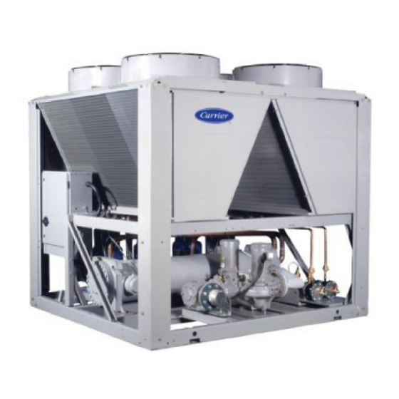
30RB060-390 Air-Cooled Chillers and
30RB080-390 Air-Cooled Chillers with
Greenspeed
Refrigerant Circuit . . . . . . . . . . . . . . . . . . . . . . . . . . . . . . 71
• DEHYDRATION
BACnet Communication Option Wiring . . . . . . . . . 71
SAFETY CONSIDERATIONS
Installing, starting up, and servicing air-conditioning
equipment can be hazardous due to system pressures, electrical
components, and equipment location.
Only trained, qualified installers and service mechanics
should install, start up, and service this equipment.
Untrained personnel can perform basic maintenance func-
tions such as cleaning coils. All other operations should be
performed by trained service personnel.
When working on the equipment, observe precautions in the
literature and on tags, stickers, and labels attached to the
equipment.
• Follow all safety codes.
• Keep quenching cloth and fire extinguisher nearby when
brazing.
• Wear safety glasses and work gloves.
• Use care in handling, rigging, and setting bulky
equipment.
Electrical shock can cause personal injury and death. Shut
off all power to this equipment during installation. There
may be more than one disconnect switch. Tag all discon-
nect locations to alert others not to restore power until work
is completed.
IMPORTANT: This equipment generates, uses, and can
radiate radio frequency energy and if not installed and
used in accordance with these instructions may cause
radio interference. It has been tested and found to comply
with the limits of a Class A computing device pursuant to
International Standard in North America EN 61000-2/3,
which are designed to provide reasonable protection
against such interference when operated in a commercial
environment.
This system uses Puron
higher pressures than R-22 and other refrigerants. No other
refrigerant can be used in this system. Failure to use gage
set, hoses, and recovery systems designed to handle Puron
refrigerant (R-410A) may result in equipment damage or
personal injury. If unsure about equipment, consult the
equipment manufacturer.
Form 30RB-21SI
Pg 1
AquaSnap
®
Technology
WARNING
CAUTION
®
refrigerant (R-410A), which has
318
12-13
Replaces: 30RB-20SI
®
Page
Advertisement
Table of Contents

Subscribe to Our Youtube Channel
Related Manuals for Carrier 30RB060-390


Summary of Contents for Carrier 30RB060-390
-
Page 1: Table Of Contents
® AquaSnap 30RB060-390 Air-Cooled Chillers and 30RB080-390 Air-Cooled Chillers with Greenspeed ® Technology Installation Instructions Page CONTENTS Refrigerant Circuit ......71 Page •... -
Page 2: Introduction
For each unit or module, the final unit location must be level so that oil will equalize properly. MODULE UNITS MODULE A MODULE B RIGGING UNIT — The 30RB060-390 units are designed for 30RBF315 30RBF160 30RBF160 overhead rigging and it is important that this method be... - Page 3 unit from above to remove skid. See Fig. 24 and 25 for rigging Table 2 — Number of Lifting Points center of gravity. On export units, the top skid can be used as the spreader bars. If the unit was shipped with a shipping bag, 30RB NUMBER OF LIFTING POINTS the bag must be removed to gain access to the rigging holes in...
- Page 4 30RB – Air-Cooled AquaSnap® Chiller Design Series SEE NEXT PAGE Nominal Sizes FOR REMAINDER 060 110 360* 070 120 390* OF MODEL NUMBER 080 130 315* 090 150 330* NOMENCLATURE 100 160 345* Voltage 1 – 575-3-60 5 – 208/230-3-60 2 –...
- Page 5 Packaging/Security Options L – No Packaging 0 – Skid 1 – Skid, Top Crate, Bag 3 – Coil Trim Panels SEE PREVIOUS PAGE 4 – Skid, Coil Trim Panels 5 – Skid, Top Crate, Bag, Coil Trim Panels FOR REMAINDER 7 –...
- Page 6 a30-4732...
- Page 7 a30-4733...
- Page 8 a30-4734...
- Page 9 a30-4711...
- Page 10 a30 5332...
- Page 11 a30-4735...
- Page 12 a30-5333...
- Page 13 a30-4736...
- Page 14 a30-4737...
- Page 16 a30-4738...
- Page 17 a30-4715...
- Page 18 a30-4739...
- Page 19 a30-4589...
- Page 20 a30-4740...
- Page 21 a30-4716...
- Page 22 a30-4717...
- Page 23 a30-4718 a30-4718...
- Page 24 a30-4719...
- Page 25 AL/CU COIL UNITS WITHOUT PUMP — ENGLISH AL/CU COIL UNITS WITHOUT PUMP — SI MOUNTING WEIGHT (lb) MOUNTING WEIGHT (kg) UNIT UNIT No Pump Al/Cu* No Pump Al/Cu* 30RB 30RB Total Total 1193 1136 4111 1869 1275 1215 4317 1962 1313 1346 4600...
- Page 26 AL/CU COIL UNITS WITH SINGLE PUMP — ENGLISH AL/CU COIL UNITS WITH SINGLE PUMP — SI MOUNTING WEIGHT (lb) MOUNTING WEIGHT (kg) UNIT UNIT Single Pump Al/Cu* Single Pump Al/Cu* 30RB 30RB Total Total 1085 1127 1230 1184 4626 2103 1107 1150 1312...
- Page 27 MCHX COIL UNITS WITH SINGLE PUMP — ENGLISH MCHX COIL UNITS WITH SINGLE PUMP — SI MOUNTING WEIGHT (lb) MOUNTING WEIGHT (kg) UNIT UNIT Single Pump MCHX** Single Pump MCHX** 30RB 30RB Total Total 1008 1047 1143 1100 4298 1949 1030 1069 1220...
- Page 28 MCHX COIL UNITS WITH HEAT RECLAIM — ENGLISH MCHX COIL UNITS WITH HEAT RECLAIM — SI MOUNTING WEIGHT (lb) MOUNTING WEIGHT (kg) UNIT UNIT Heat Reclaim MCHX** Heat Reclaim MCHX** 30RB 30RB Total Total 1185 1175 1166 1176 4703 2133 1204 1196 1245...
- Page 29 5.35" [136 mm] 2.56" [65 mm] INNER SIDE OUTER SIDE 2.46" [63 mm] OF UNIT OF UNIT BASE RAIL BASE RAIL 4.87" [124 mm] 5.12" [130 mm] 1.42" [36 mm] Fig. 22 — 30RB Base Rail Cross Section 1.50 DIA. [ø38 mm] RIGGING HOLE 0'–...
- Page 30 Table 3A — Physical Data, 30RB060-300 — English UNIT 30RB OPERATING WEIGHT (lb)* Al-Cu Condenser Coil 4111 4317 4600 5932 6155 6519 7690 8045 9174 Cu-Cu Condenser Coil 4593 4799 5082 6656 6879 7243 8534 9010 10139 MCHX Condenser Coil 3783 3978 4267...
- Page 31 Table 3A — Physical Data, 30RB060-300 — English (cont) UNIT 30RB OPERATING WEIGHT (lb)* Al-Cu Condenser Coil 10,266 10,601 12,013 13,734 14,067 15,468 16,915 18,306 Cu-Cu Condenser Coil 11,472 11,807 13,460 15,181 15,514 17,157 18,845 20,477 MCHX Condenser Coil 9,475 9,799 11,064 12,772...
- Page 32 Table 3B — Physical Data, 30RB060-300 — SI UNIT 30RB OPERATING WEIGHT (kg)* Al-Cu Condenser Coil 1869 1962 2091 2697 2798 2963 3488 3649 4161 Cu-Cu Condenser Coil 2088 2181 2310 3026 3127 3292 3871 4087 4599 MCHX Condenser Coil 1716 1804 1934...
- Page 33 Table 3B — Physical Data, 30RB060-300 — SI (cont) UNIT 30RB OPERATING WEIGHT (kg)* Al-Cu Condenser Coil 4666 4819 5461 6243 6394 7031 7686 8321 Cu-Cu Condenser Coil 5215 5367 6118 6901 7052 7799 8566 9308 MCHX Condenser Coil 4297 4443 5019 5793...
- Page 34 Table 4A — Physical Data — 30RB315-390 — English UNIT 30RB OPERATING WEIGHT (Module A/Module B, lb)* Al-Cu Condenser Coil 10,266/10,266 10,601/10,266 10,601/10,601 12,013/10,601 12,013/12,013 Cu-Cu Condenser Coil 11,472/11,472 11,807/11,472 11,807/11,807 13,460/11,807 13,460/13,460 MCHX Condenser Coil 9,475/9,475 9,799/9,475 9,799/9,799 11,064/9,799 11,064/11,064 REFRIGERANT TYPE R-410A, EXV Controlled System...
- Page 35 Table 4B — Physical Data — 30RB315-390 — SI UNIT 30RB OPERATING WEIGHT (Module A/Module B, kg)* Al-Cu Condenser Coil 4656/4656 4808/4656 4808/4808 5448/4808 5448/5448 Cu-Cu Condenser Coil 5203/5203 5354/5203 5354/5354 6104/5354 6104/6104 MCHX Condenser Coil 4297/4297 4444/4297 4444/4444 5018/4444 5018/5018 REFRIGERANT TYPE R-410A, EXV Controlled System...
- Page 36 Fig. 24 — Unit Rigging Label Detail 30RB060-150...
- Page 37 Fig. 25 — Unit Rigging Label Detail 30RB160-300...
-
Page 38: Step 2 - Remove Compressor Rack
FOR UNITS EQUIPPED WITH COMPRESSOR SOUND Step 2 — Remove Compressor Rack Holddown BLANKETS — The sound blanket top covers are shipped in- The 30RB units are shipped with holddown bolts Bolts — side the control box(es) for the unit. Remove the top covers securing the compressor rail assembly to the unit base frame. - Page 39 Failure to use the strainers represents abuse and may port for the piping. If compressor and cooler grilles have been impair or otherwise negatively affect the Carrier product added, holes must be cut in the grilles for field piping and warranty.
-
Page 40: Units Without Hydronic Pump Package
Failure to use the strainers represents abuse and may the drain piping (in the same manner as the chilled water impair or otherwise negatively affect the Carrier product piping) for at least 12 in. (305 mm) from the unit. -
Page 41: Head Pressure Control
3-way valve location. All piping must follow standard piping valve and the heat reclaim condenser. See Fig. 33A. If the techniques. Refer to Carrier System Design Manual or appro- pumps are too far away from the condenser, a second option is priate ASHRAE (American Society of Heating, Refrigerating, to install the 3-way control valve close to the condenser. -
Page 42: For All Units
NOTE: Locate the 3-way valve as close as possible to the System Piping — Proper system design and installation proce- chiller to minimize head pressure control response time. dures should be followed closely. The system must be constructed with pressure tight components and thoroughly MODULATING 3-WAY tested for leaks. - Page 43 Tank Installation Master Chiller Control Pump and Check Valve or Isolation Valve Slave Chiller GOOD Control Pump and Check Valve or Isolation Valve Dual Chiller LWT Sensors and Wells GOOD a30-3987ef a30-3185ef LEGEND — Leaving Water (Fluid) Temperature Field Wiring Fig.
-
Page 44: Step 5 - Fill The Chilled Water And Heat Reclaim
SYSTEM Do not circulate water through unit without strainers in POT FEEDER AND place. Failure to use the strainers represents abuse and may TRANSFER PUMP impair or otherwise negatively affect the Carrier product DILUTED CLEANING warranty. AGENT 1. Install a temporary bypass around the chiller to avoid circulating dirty water and particulates into the pump package and chiller during the flush. -
Page 45: System Pressurization
SYSTEM PRESSURIZATION — A proper initial cold fill return water line that is common to all pumps, providing that pressure must be established before filling of the unit. The the tank is properly sized for combined system volume. initial cold fill pressure is the pressure applied at the filling If the application involves two or more chillers in a primary point to fill a system to its highest point, plus a minimum secondary system, a common place for mounting the expan-... - Page 46 Head Pressure (m) ft of fluid 8.19 in 1750 RPM (21.3) 70 (18.3) 60 7.50 in (15.2) 50 7.00 in 7.5 hp 6.50 in (12.2) 40 6.00 in 5 hp (9.1) 30 (6.1) 20 3 hp (3.0) 10 2 hp NPSHr (0.0) 0 (gpm)
- Page 47 Head Pressure 8.19 in (m) ft of fluid 1750 RPM (18.3) 60 (14.6) 48 6.50 in 15 hp (11.0) 36 6.00 in 10 hp (7.3) 24 7.5 hp 5 hp (3.7) 12 3 hp NPSHr (0.0) 0 (gpm) (0.00) (10.09) (20.19) (30.28) (40.38)
- Page 48 Head Pressure (m) ft of fluid (42.7) 140 3450 RPM (36.6) 120 (30.5) 100 (24.4) (18.3) (12.2) (6.1) NPSHr (0.0) 1000 (gpm) a30-5468 (0.00) (12.62) (25.24) (37.85) (50.47) (63.09) (l/s) Flow Rate LEGEND NPSHr — Net Positive Suction Head (Pressure) Required NOTE: Refer to the 30RB nomenclature, Fig.
- Page 49 Head Pressure (m) ft of fluid 1750 RPM 8.19 in 8.15 in (18.3) 60 7.30 in (14.6) 48 6.50 in (11.0) 36 6.00 in 7.5 hp 5 hp (7.3) 24 3 hp 2 hp (3.7) 12 1.5 hp 1 hp NPSHr (0.0) 0 (gpm)
- Page 50 Head Pressure (m) ft of fluid 3450 RPM 6.19 in (45.7) 150 6.10 in (36.6) 120 5.40 in (27.4) 90 20 hp (18.3) 60 15 hp 10 hp 7.5 hp (9.1) 30 5 hp 3 hp NPSHr (0.0) 0 (gpm) (0.00) (6.31) (12.62)
- Page 51 Head Pressure (m) ft of fluid (42.7) 140 3450 RPM (36.6) 120 (30.5) 100 (24.4) (18.3) (12.2) (6.1) NPSHr (0.0) (gpm) (0.00) (6.31) (12.62) (18.93) (25.24) (31.55) (l/s) a30-5472 Flow Rate LEGEND NPSHr — Net Positive Suction Head (Pressure) Required NOTE: Refer to the 30RB nomenclature, Fig.
-
Page 52: Set Water Flow Rate
Although this does reduce power consumption slightly, it may not be the desirable method of reducing the NOTE: Carrier recommends a differential pressure gage when flow, especially if a large reduction is needed. measuring pressures across the pumps or balancing valves. -
Page 53: Pump Vfd
Trimming should only be done by a qualified machine shop that has experience in this operation. Contact When changing set points, assure values are within the your local Carrier representative for a recommended machine pump curve for the pump provided with the unit. shop. -
Page 54: Preparation For Year-Round
25.2 12.6 37.8 50.5 63.1 75.7 88.3 to the chilled water. The Carrier warranty does not cover dam- Fig. 54 — 30RB210-300 age due to freezing. Cooler Pressure Drop Curve... - Page 55 HEAT RECLAIM VESSEL PRESSURE DROP CURVES 30RB 60-110 TON (179.4kPa) (149.5kPa) (119.6 kPa) (89.7kPa) (59.8kPa) (29.8kPa) 0.00 6.31 12.62 18.93 25.24 31.55 37.85 44.16 a30-4822 Fig. 55 — 30RB060-110 Optional Heat Reclaim Pressure Drop Curves HEAT RECLAIM VESSEL PRESSURE DROP CURVES 30RB 120-190 TON (149.5kPa) (119.6 kPa)
-
Page 56: Preparation For Winter Shutdown
2. Ensure that power is available to the chiller at all times, of a power failure. The Carrier warranty does not cover even during the off-season, so that the pump, cooler heat- damage due to freezing. -
Page 57: Heat Reclaim System
Consult reset the CB-CDHT (if opened) to restore power. the Controls, Start-Up, Operation, Service and Trouble- shooting guide provided with 30RB060-390 units for cor- Step 6 — Make Electrical Connections rect procedure. Improper pump rotation can cause permanent damage to pump impeller and housing. -
Page 58: Dual Chiller Control Option
The piping must be drilled and tapped for the well. Select a location that will allow for removal of the thermistor without any restrictions. See Fig. 60 and 61. Table 9 — Control and Power Connections, 30RB060-390 MAIN POWER 30RB UNIT SIZE... - Page 59 a30-5708...
- Page 60 a30-5709...
-
Page 61: Field Control Option Wiring
(–) LEGEND NOTES: 1. Terminals 1 and 2 of TB7 are for external connection of heat Field Control Wiring reclaim condenser water valve. Factory-Installed Wiring 2. Terminals 3 and 4 of TB7 are for external connection of field- supplied heat reclaim water pump control relay. 3. - Page 62 Table 10A — 30RB060-190 Electrical Data — Single Point Units UNIT VOLTAGE NO HYDRONIC PACKAGE 3 HP PUMP, 1750 RPM 5 HP PUMP, 1750 RPM UNIT 30RB Supplied MOCP MOCP MOCP Rec Fuse Rec Fuse Rec Fuse V-Hz (3 Ph) Size Size Size...
- Page 63 Table 10A — 30RB060-190 Electrical Data — Single Point Units (cont) UNIT VOLTAGE 7.5 HP PUMP, 1750/3450 RPM 10 HP PUMP, 3450 RPM 15 HP PUMP, 3450 RPM UNIT 30RB Supplied MOCP MOCP MOCP Rec Fuse Rec Fuse Rec Fuse V-Hz (3 Ph) Size Size...
- Page 64 Table 10B — 30RB210-390 Electrical Data — Single Point Units UNIT VOLTAGE NO HYDRONIC PACKAGE 3 HP PUMP, 1750 RPM 5 HP PUMP, 1750 RPM UNIT 30RB Supplied MOCP MOCP MOCP Rec Fuse Rec Fuse Rec Fuse V-Hz (3 Ph) Size Size Size...
- Page 65 Table 11A — 30RB060-190 Electrical Data — Dual Point Units UNIT VOLTAGE NO HYDRONIC PACKAGE 3 HP PUMP, 1750 RPM 5 HP PUMP, 1750 RPM 30RB Supplied MOCP MOCP MOCP UNIT V-Hz Fuse Fuse Fuse SIZE (3 Ph) Size Size Size 208/230-60 168.8/141.5...
- Page 66 Table 11A — 30RB060-190 Electrical Data — Dual Point Units (cont) UNIT VOLTAGE 7.5 HP PUMP, 1750/3450 RPM 10 HP PUMP, 3450 RPM 15 HP PUMP, 3450 RPM 30RB UNIT Supplied MOCP MOCP MOCP Rec Fuse Rec Fuse Rec Fuse V-Hz (3 Ph) SIZE Size...
- Page 67 Table 11B — 30RB210-390 Electrical Data — Dual Point Units UNIT VOLTAGE NO HYDRONIC PACKAGE 3 HP PUMP, 1750 RPM 5 HP PUMP, 1750 RPM Supplied MOCP MOCP MOCP UNIT 30RB Rec Fuse V-Hz (3 Ph) Fuse Fuse Size Size Size 208/230-60 626.7/353.9...
- Page 68 Table 12 — Condenser Fan Electrical Data STANDARD CONDENSER FANS UNIT UNIT VOLTAGE 30RB V-Hz (3 Ph) Circuit A Quantity FLA (each) Circuit B Quantity FLA (each) Circuit C Quantity FLA (each) 208/230-60 11.9 11.9 — — 380-60 — — 060, 070 460-60 —...
- Page 69 Table 14 — Compressor Electrical Data COMPRESSOR COMPRESSOR COMPRESSOR UNIT UNIT VOLTAGE 30RB V-Hz (3 Ph) RLA LRA RLA LRA RLA LRA RLA LRA RLA LRA RLA LRA RLA LRA RLA LRA RLA LRA RLA LRA RLA LRA RLA LRA 208/230-60 75.0 485 75.0 485 —...
-
Page 70: Carrier Comfort Network
MINIMUM LOAD ACCESSORY — If minimum load acces- ate colors for different colored cables. sory is required, contact your local Carrier representative for 3. Connect the red wire to (+) terminal on TB3 of the plug, more details. For installation details, refer to separate installa- the white wire to COM terminal, and the black wire to the tion instructions supplied with the accessory package. -
Page 71: Unit Security/Protection Accessories
TP network segment communications at 9600 bps, 19.2 kbps, port to plug in the Navigator device. Contact your local Carrier 38.4 kbps, or 76.8 kbps. representative for more details. For installation details, refer to... - Page 72 BT485 TERMINATOR BACNET CONNECTION POWER LED (BAS PORT) Tx1 LED Rx1 LED Tx2 LED Rx2 LED BACNET BAUD RATE DIP SWITCHES EIA-485 JUMPERS ADDRESS ROTARY SWITCHES RUN LED ERROR LED Fig. 63 — UPC Open Controller Fig. 64 — Network Wiring...
- Page 73 Fig. 65 — BT485 Terminator Installation Table 16 — MS/TP Wiring Recommendations SPECIFICATION RECOMMMENDATION Cable Single twisted pair, low capacitance, CL2P, 22 AWG (7x30), TC foam FEP, plenum rated cable Conductor 22 or 24 AWG stranded copper (tin plated) Insulation Foamed FEP 0.015 in.
- Page 76 © Carrier Corporation 2013 Manufacturer reserves the right to discontinue, or change at any time, specifications or designs without notice and without incurring obligations. Catalog No. 04-53300124-01 Printed in U.S.A. Form 30RB-21SI Pg 76 12-13 Replaces: 30RB-20SI...
Need help?
Do you have a question about the 30RB060-390 and is the answer not in the manual?
Questions and answers