Advertisement
Table of Contents
- 1 Table of Contents
- 2 Features/Benefits
- 3 Model Number Nomenclature
- 4 AHRI Capacity Ratings
- 5 Physical Data
- 6 Options and Accessories
- 7 Base Unit Dimensions
- 8 Accessory Dimensions
- 9 Selection Procedure
- 10 Performance Data
- 11 Typical Piping and Wiring
- 12 Electrical Data
- 13 Controls
- 14 Typical Control Wiring Schematic
- 15 Application Data
- 16 Guide Specifications
- Download this manual
Copyright 2011 Carrier Corporation
Product
Data
with PURON
a30-4827
a30-5347
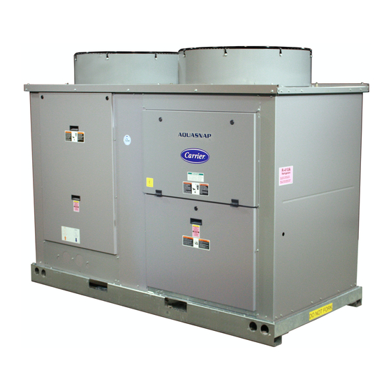
30RAP010-090
Air-Cooled Chillers
®
Refrigerant (R-410A)
10 to 90 Nominal Tons
(35 to 316 Nominal kW)
The AquaSnap chiller is an effective all-
in-one package that is easy to install and
easy to own. AquaSnap chillers operate
quietly and efficiently. Value-added
features include:
• Rotary scroll compression
• HFC Puron
• Low-sound AeroAcoustic™ fan system
• Easy to use ComfortLink™ controls
• Optional integrated hydronic pump
package with VFD (variable frequency
drive) compatible motors, with optional
VFD on 070-090 models
• Microchannel condenser coil
technology
a30-4826
• Accessory fluid storage tank on 010 -
060 models
• Optional digital scroll compressors
Features/Benefits
Carrier's superior chiller
design provides savings at
initial purchase, at installa-
tion, and for years afterward.
Costs less right from the start
Carrier's AquaSnap chillers feature a
compact, all-in-one package design that
installs quickly and easily on the ground
or the rooftop. The optional pump and
hydronic components are already built
in; this costs less than buying and install-
ing the components individually. The
chiller's fully integrated and pre-assem-
bled hydronic system installs in minutes.
No other chiller in this class installs so
easily and inexpensively. The preassem-
bled and integrated hydronic module uti-
lizes top-quality components and pumps
to ensure years of reliable operation.
Use of the optional fluid storage tank,
available on size 010-060 models, re-
duces installation costs and ensures suffi-
cient fluid volume is available for close-
coupled and process cooling applica-
tions. The AquaSnap unit's high effi-
ciency keeps costs down.
®
AQUASNAP
®
refrigerant (R-410A)
Form 30RAP-7PD
Advertisement
Table of Contents


Need help?
Do you have a question about the Aquasnap 30RAP070 and is the answer not in the manual?
Questions and answers