
Summary of Contents for Will Burt Night Scan Chief
- Page 1 Night Scan Chief NIGHT SCAN CHIEF INSTALLATION, OPERATION & MAINTENANCE MANUAL The Will-Burt Company 169 S. Main Street Orrville, OH 44667 www.willburt.com Revision 1, December 2007 Revision 1...
- Page 3 Night Scan Chief WARRANTY The Manufacturer warrants its products to be free from defects in material and workmanship for a period of one year from the date of shipment from the factory. The Manufacturer shall not be responsible for any damage resulting to or caused by...
-
Page 5: Table Of Contents
Night Scan Chief TABLE OF CONTENTS SAFETY SUMMARY INTRODUCTION 1.1 Safety Precautions ..........................1-1 1.2 Introduction............................1-1 1.3 Description.............................1-1 1.4 Reference Data .............................1-2 1.5 Technical Information ..........................1-2 INSTALLATION 2.1 Introduction............................2-1 2.2 Tools and Materials Required for Installation..................2-1 2.3 Unpacking..............................2-2 2.4 Attaching to vehicle ..........................2-2 2.5 Connecting the Push/Pull Switch (Junction Box) ..................2-4... - Page 6 Actuator and Proximity Sensors ....................3-2 Figure 3-2 Photo Interrupter and Flag......................3-3 Figure 3-3 Cover and Screw Removal for Manual Stow (Night Scan Chief only) ........3-7 Figure 4-1 Proximity Switch Adjustment ....................... 4-3 Figure 4-2 LED Location and Function ......................4-3 Figure 4-3 Flag Settings..........................
- Page 7 Night Scan Chief SAFETY SUMMARY SIGNAL WORD DEFINITION Per the ANSI Z535.4 standard, the following signal words and definitions are used to indicate hazardous situations: DANGER indicates an imminently hazardous situation that, if not avoided, will result in death or serious injury.
- Page 8 Night Scan Chief SPECIFIC SAFETY PRECAUTIONS The following are safety precautions that are related to specific procedures and therefore appear elsewhere in this publication for emphasis. These are recommended precautions that personnel must understand and apply during specific phases of installation, operation and maintenance.
- Page 9 Night Scan Chief Safety Instruction -Trained Personnel Only! Only trained and qualified personnel should perform installation, adjustments, and servicing. Only a properly trained and qualified certified electrician should perform electric installations and service. When relamping an installed fixture, make sure all power to fixture is off and that the fixture is cool Safety Instruction –...
-
Page 11: Introduction
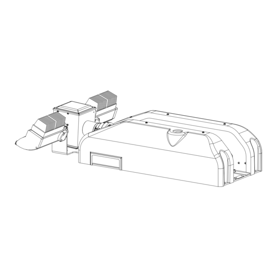
Air pressure required to extend the mast is provided by a compressor unit mounted within the Night Scan Chief. The unit is designed for installation on any vehicle for the purpose of providing on the scene temporary lighting. Refer to Figure 1-1 for identification of the major components of the Night Scan Chief unit. -
Page 12: Reference Data
The reference data for the Chief given in Table 1-1 is not inclusive of all models. Please refer to product literature or www.willburt.com for additional information including length, width and height information. Table 1-1. Reference Data Night Scan Chief Model No. 140DC 300DC... -
Page 13: Figure 1-2 Mast Loads
Night Scan Chief Mast Loads It is important that the mast be securely mounted to a sturdy platform, which will not overturn during operational loading of the mast. Figure 1-2 provides loading information for the mast, which can be expected during operation. All values given are in lbs. -
Page 15: Installation
Be sure to read and understand the entire installation procedure before you begin. 2.2 TOOLS AND MATERIALS REQUIRED FOR INSTALLATION Table 2-1 provides a list of tools and materials required to install and test the Night Scan Chief. Wrenches Crimping tool or Solder set... -
Page 16: Unpacking
2.4 ATTACHING TO VEHICLE If the Night Scan Chief is to be mounted in a well, be certain that adequate drainage is provided. A minimum of (4) drain holes (one per corner) at least one inch in diameter is recommended. While the unit has been designed to withstand adverse environmental conditions, it cannot be submerged. -
Page 17: Figure 2-2 Night Scan Base Mounting Hole Locations
Night Scan Chief 33.0 BASE MOUNTING HOLES ( n .56" SEE NOTE) SADDLE MOUNTING HOLES ( n .56" SEE NOTE) 11.0 40 1/8" (6FT. MAST) 46 1/8" (7.5FT. MAST) Figure 2-2 Night Scan Base Mounting Hole Locations Junction Box Installation The junction box serves as an interface between the Hand Held Remote Control and the Night Scan Base. -
Page 18: Connecting The Push/Pull Switch (Junction Box)
Night Scan Chief Surface mounting For a surface mount installation, four #8 screws, nuts and lock washers must be provided by the installer. The screw length should be ¾ inch plus the panel thickness. Remove the junction box cover and mount unit through the counter bored holes in the junction box. -
Page 19: Connecting The Interlock Contact (Optional)
Night Scan Chief Table 2-2. Handheld Remote Control Connector Pin-out To Pin of DC Power HHRC Pin Pin Function Recommended Wire Ga. Connector + Signal + Power - Power - Signal Figure 2-5 Hand Held Receptacle Pins 2.7 CONNECTING THE INTERLOCK CONTACT (OPTIONAL) The Chief provides an interlock relay contact output to enhance integration into vehicle safety circuitry. -
Page 20: Installing The Warning Light
2.10 MULTIPLEX SYSTEMS OPERATING AT 24 VOLTS When operating at 24 volts, the Night Scan Chief “chops” the voltage sent to the 12 vdc motors is the system. As a result of this starting and stopping, voltage might be fed back through the power wires and into the power supply. - Page 21 Night Scan Chief present. Contact with combustible materials can cause ignition resulting in fire or explosion. Before operating the Chief, be sure that there are no overhead obstructions and that there are no power lines within 20 feet of the mast. Visually inspect the unit for any damage. If damage is apparent, do not use the mast.
-
Page 23: Operating Instructions
Night Scan Chief CHAPTER 3 OPERATING INSTRUCTIONS All operators must read the Operation section of this manual and be properly trained. Keep personnel clear of mast while during operation. For outdoor use only. Do not use in areas that have been classified as hazardous as defined in Article 500 of the National Electric Code. -
Page 24: Theory Of Operation - Mechanical
Night Scan Chief – Mast The Night Scan Chief operates using a DC powered actuator to drive the mast from nest to 90 degrees. When at 90 degrees, a magnetic sensor detects the actuator position and prevents further driving of the actuator. -
Page 25: Theory Of Operation - Electrical
Another key component of the control is an initialization circuit. In an NFPA compliant installation, a completely stowed Night Scan Chief draws zero current and cannot be extended or operated until the initiate circuit is engaged. Included in this initialization circuit is an input for a safety interlock. This can be used for an emergency stop, or other interlock function such as a “Park/Neutral”... -
Page 26: Push/Pull Switch - Non-Nfpa Installations
Night Scan Chief control by pulling the switch operator. This is a momentary function, and the switch will return itself to a neutral position on its own. Secondly, it functions as an emergency stop when the switch operator is pushed all the way in. -
Page 27: Raising The Mast
Press the “Mast Down” button until the mast has completely stowed. Note : In the Night Scan Chief, during the process of raising the mast, the mast will first be inclined to a position perpendicular to its mounting surface by an actuator. Once the control senses it is in this position, air pressure will be applied to the tube sections to raise the mast further into the air. -
Page 28: Emergency Stow (Loss Of Power)
Remote Control. Note : To ensure proper seating of the RCP in Night Scan Chief saddle, the control watches for an increase of current from the actuator. Once this has been satisfied, the control will shut itself off on NFPA compliant installations. -
Page 29: Figure 3-3 Cover And Screw Removal For Manual Stow (Night Scan Chief Only)
Night Scan Chief COVER SCREWS RIGHT SIDE COVER KNURLED PIN & E-CLIP Figure 3-3 Cover and Screw Removal for Manual Stow (Night Scan Chief only) Revision 1... -
Page 31: Maintenance And Service Instructions
This section of the manual describes routine maintenance procedures and covers general service information. Refer to Chapter 5 for exploded views of the Night Scan Chief and the accompanying Tables with item descriptions and part numbers, which may be used for ordering replacement parts. -
Page 32: Adjustments
Night Scan Chief 6. Exhaust the mast completely. Allow several minutes for the lubricant to settle and spread around the wear ring and seal at the bottom of each mast section. Keep hands clear of the descending collars while the mast is being lowered to avoid pinching. - Page 33 Night Scan Chief 7. Cycle the mast several times, checking that the mast is plumb each time. Adjust the switch if necessary. 8. Replace cover. MAST 90° PROX SWITCH MAGNET PROX SWITCH UPPER JAM NUT LOWER JAM NUT Figure 4-1...
- Page 34 Adjusting the Magnetic Switch The Magnetic Switch is located on the mast base tube. In the Night Scan Chief, the magnetic switch senses a magnet located in the top tube and serves to indicate that the mast has exhausted all air and that it is safe to nest into the saddle.
-
Page 35: Figure 4-3 Flag Settings
Night Scan Chief 9. Initiate and raise the mast to 90 degrees. Replace the RCP cover. POINTERS @ HOME POSITION Figure 4-3 Flag Settings DIP switch setting Chief base boards require that the DIP switch be set appropriately to determine operational mode. RCP boards require that the DIP switch be set appropriately to determine operational mode. -
Page 36: Figure 4-4 Dip Switch Location: Chief Base Board
Night Scan Chief Figure 4-4 DIP switch location: Chief base board To set the operational mode for the RCP board, locate the DIP switch S1 (see Figure 4-5) and set the DIP switch as follows: • Position 1 - Close to cause the RCP to self stow if there is an error. -
Page 37: System Schematics
Night Scan Chief 4.4 SYSTEM SCHEMATICS A system schematic is given in order to aid in electrical troubleshooting as outlined in the following section. 20 GA TWISTED PAIRS 4032504 16 FT CABLE 18 GA TO HHRC 4032505 30 FT CABLE... -
Page 38: Figure 4-8 Night Scan Chief Base Wiring
Night Scan Chief Figure 4-8 Night Scan Chief Base Wiring Revision 1... -
Page 39: Figure 4-9 Night Scan Chief Remote Control Positioner (Rcp) Schematic
Night Scan Chief Figure 4-9 Night Scan Chief Remote Control Positioner (RCP) Schematic Revision 1... -
Page 40: Troubleshooting Electrical
Night Scan Chief 4.5 TROUBLESHOOTING ELECTRICAL Operating Environment One of the most common causes of improper operation is trying to operate outside of the stated system requirements. (See section Table 1-1for DC power requirements). A good method of checking the voltage at the Chief is to connect a voltmeter to the wires in the junction box powering the Remote Control(s) (pins B and C of J1 (see schematics in section 4.4). - Page 41 Night Scan Chief mast path, and confirm that the proximity switch is being properly activated. Err 1,07 Unrecoverable The Base board has Indicates a software Communication not sent out problem. Notify Will- Error communications Burt recently Err 1,08 Software Fault...
- Page 42 Night Scan Chief schematics in section 4.4 Err 1,13 Mast Nested The proximity switch There may be a Proximity Switch sensing the mast wiring problem, or a Disagreement actuator at almost defective proximity nested position has switch. Check the conflicting...
- Page 43 Night Scan Chief outputs wired and 3 of J3 may backwards need to be swapped. The proximity switch not being energized could also cause it. Place a magnet close to the switch to check before changing wiring. Refer to system schematics in section 4.4...
-
Page 44: Table 4-2. List Of Remote Control Positioner Board Faults
Night Scan Chief 4.5.1.2 RCP Board The remote control positioner (RCP) board is located in the positioner at the top of the mast and is assigned unit number two (2). It should be noted that having the RCP covers off can cause improper RCP operation, especially outdoors. - Page 45 Night Scan Chief Err 2,07 Unrecoverable The RCP board Bad connection in Communicatio has not sent out communications link, or n Error communications RCP is not powered or is recently inadequately powered. Make sure the power at the RCP board is at least 10.5 volts.
- Page 46 Night Scan Chief Err 2,13 Pan Right The left pan Check to make sure the Limit photosensor was pan flag is not located in made before the between the two right photosensor photosensors. If it is, indicating wrap slowly move the RCP...
-
Page 47: Table 4-3. List Of Remote Control Board Faults
Night Scan Chief 4.5.1.3 Remote Control(s) Board The handheld remote control board is located in the handheld unit and is assigned unit number three (3). The Remote Control board may generate the messages of Table 4-3: Table 4-3. List of Remote Control Board Faults... -
Page 48: Table 4-4. List Of Warning Codes
Night Scan Chief Warning Codes Warning codes are presented on the LED eight-digit alphanumeric display. The codes are a combination of numbers that identify both the general location of the warning, and the type of warning. The first of two numbers is a single digit number indicating which board. -
Page 49: Troubleshooting Mechanical
Night Scan Chief 4.6 TROUBLESHOOTING MECHANICAL Table 4-5. Mechanical Troubleshooting Symptom Root Issue Troubleshooting Sequence Mast sticking Mast is dirty and/or requires 1) Clean and lubricate mast. during extension or lubrication. 2) If condition continues, mast requires retraction overhaul. Mast leaks down Air leak in mast or Use a soapy water solution to pinpoint the leak. -
Page 51: Parts List
Night Scan Chief CHAPTER 5 PARTS LIST 5.1 PART LISTS Table 5-1. Night Scan Chief Base Assembly Parts List Mark No. Description Part Number Base Plate 4121702 Base Circuit Board 4118301 Saddle Assembly 4122201 Compressor Assembly 4141101 Actuator 4136302 Mast Assembly, 6 ft 4142204 Mast Assembly, 7.5 ft... -
Page 52: Figure 5-1 Exploded View - Base Left Side
Night Scan Chief Shim Washer 4122601 External Retaining Ring 3401 Spacer 4121301 Internal Retaining Ring 3783 Pivot Block 4121001 Sleeve Bearing 4120401 Base Cover Left 4143002 Base Cover Right 4141002 Handheld Remote Control 4183601 Figure 5-1 Exploded View - Base Left Side... -
Page 53: Figure 5-2 Base Right Side
Night Scan Chief Figure 5-2 Base Right Side MAST BOTTOM Figure 5-3 Exploded View – Mast Pivot Assembly Revision 1... -
Page 54: Table 5-2. Remote Control Positioner Assembly Parts List
Night Scan Chief Table 5-2. Remote Control Positioner Assembly Parts List Mark No. Description Part Number Remote Control Positioner Frame 4124102 Circuit Board, RCP 4118401 Pan Bearing Housing 4124302 Tilt Coupling 4124801 Horizontal Bearing 913435 Bearing Retainer 4124202 Pan Bearing Spacer... -
Page 55: Figure 5-4 Exploded View - Remote Control Positioner (Rcp)
Night Scan Chief 15 12 Figure 5-4 Exploded View - Remote Control Positioner (RCP) Revision 1... -
Page 57: Revisions
Night Scan Chief CHAPTER 6 REVISIONS Revision 0, October 2007: Initial Release. Revision 1, December 2007: Update base schematic Figure 4-8 to correct inclination motor wiring and add capacitor. Add 2.10 to address capacitor use in 24 vdc multiplex installations. -
Page 59: Software Revisions
Night Scan Chief CHAPTER 7 SOFTWARE REVISIONS 7.1 INTRODUCTION There are several circuit boards in the Chief system. Each has its own microcontroller with associated software. A person may “query” the software revisions by simultaneously holding down both Remote Control tilt buttons (up, down). The revision levels can then be viewed as they scroll across the alphanumeric display. -
Page 60: Appendices
Night Scan Chief CHAPTER 8 APPENDICES Revision 1... - Page 61 MATERIAL SAFETY DATA SHEET The Will-Burt Company Orrville, Ohio 330-682-7015 SECTION A: IDENTIFICATION AND EMERGENCY INFORMATION Product Name: Mast Lubrication 900600 Chemical Name: Cas Number: Not Applicable (N/A) Chemical Family: Industrial Metalworking Compound Emergency Telephone Number: Revision Date: 440-543-9845 (Etna) 5/3/00 HMIS RATING: H= 1 F= 1...
- Page 62 SECTION D: PHYSICAL HAZARDS Stability: Conditions to Avoid: Stable Strong Oxidants Incompatibility: Strong Oxidants Decomposition Products: Highly dependent on combustion conditions. Mixture of air-borne solid, liquid and gases evolve upon pyrolysis or combustion of this product. CO and other organic compounds may be formed upon combustion.
- Page 63 SECTION F: EMERGENCY AND FIRST AID PROCEDURES Skin contact: Remove contaminated clothing and wash with soap and water. If irritation occurs get medical attention. Eye contact: Flush with water for 15 minutes. If irritation occurs get medical attention. Ingestion: Do not induce vomiting. Get medical attention. SECTION G: SPECIAL PROTECTION / SPILL AND LEAK PROCEDURES Ventilation: Local exhaust –...
- Page 64 WILL-BURT PRODUCT REGISTRATION AND EVALUATION RETURN WITHIN 90 DAYS FROM DATE OF PURCHASE PLEASE COMPLETE THIS FORM AND RETURN TO WILL-BURT USING THE PREPAID SELF- ADDRESSED ENVELOPE WHICH HAS BEEN PROVIDED. THANK YOU FOR YOUR ASSISTANCE. CUSTOMER NAME: _____________________________________DATE: _______________ ADDRESS: __________________________________________________________________________ CITY / STATE / ZIP: ________________________PHONE No.
- Page 65 ARE SATISFIED WITH THE APPEARANCE OF THE PRODUCT? YES _______NO_________ IF NO EXPLAIN : _____________________________________________________________________________ _____________________________________________________________________________ _____________________________________________________________________________ _____________________________________________________________________________ RATE THE INSTALLATION / OPERATION / SERVICE INSTRUCTIONS. GOOD ____ FAIR ____ POOR_____ DO YOU HAVE ANY SUGGESTIONS FOR IMPROVING THE INSTALLATION / OPERATION / SERVICE INSTRUCTIONS? IF YES, EXPLAIN: _____________________________________________________________________________ _____________________________________________________________________________...
Need help?
Do you have a question about the Night Scan Chief and is the answer not in the manual?
Questions and answers