Table of Contents
Advertisement
FCC and IC Compliance Statement
PINPOINT KEY FOB, FCC ID ‑ MVU10148
ACMA: N2523
IC: 6094A‑09291, 6094A‑09305
This device complies with part 15 of the FCC Rules. Operation is subject to the
following two conditions:
1. This device may not cause harmful interference.
2. This device must accept any interference received including interference
that may cause undesired operation.
This device complies with FCC Rules. Changes or modifications not expressly
approved by MotorGuide could void the user's authority to operate the
equipment.
The MotorGuide Pinpoint GPS System complies with Industry Canada RSS‑210
standard. See RSS‑GEN 7.1.5. The term "IC:" before the certification/
registration number only signifies that registration was performed based on a
Declaration of Conformity indicating that Industry Canada technical
specifications were met. The term "IC:" before the certification/registration
number does not imply that Industry Canada approved the equipment.
EU Compliance Statement
Attwood Corporation hereby declares that the Motorguide Pinpoint GPS System
is in compliance with the essential requirements and other relevant provisions of
the 99/5/EC R&TTE directive.
A copy of the original CE Declaration of Conformity is on our website at http://
www.motorguide.com/support/certifications.
Environmental Compliance Statement
All MotorGuide products that are subject to the 2002/96/EC WEEE directive are
compliant with the WEEE marking requirement. Such products are marked with
the "crossed‑out wheelie bin" WEEE symbol (shown, below) in accordance with
European Standard EN50419.
eng
54539
i
Advertisement
Table of Contents

Related Manuals for MotorGuide Pinpoint


Summary of Contents for MotorGuide Pinpoint
- Page 1 A copy of the original CE Declaration of Conformity is on our website at http:// www.motorguide.com/support/certifications. Environmental Compliance Statement All MotorGuide products that are subject to the 2002/96/EC WEEE directive are compliant with the WEEE marking requirement. Such products are marked with the "crossed‑out wheelie bin" WEEE symbol (shown, below) in accordance with European Standard EN50419.
-
Page 2: Thank You
Thank You Thank you for purchasing the MotorGuide Pinpoint GPS Navigation System. The Pinpoint GPS Navigation System is designed to enhance the precision control and functionality of your MotorGuide trolling motor. We're confident that the Pinpoint GPS will enhance your fishing experience and we appreciate that you chose MotorGuide. - Page 3 K‑planes, Mariner, MerCathode, MerCruiser, Mercury, Mercury with Waves Logo, Mercury Marine, Mercury Precision Parts, Mercury Propellers, Mercury Racing, MotorGuide, OptiMax, Quicksilver, SeaCore, Skyhook, SmartCraft, Sport‑Jet, Verado, VesselView, Zero Effort, Zeus, #1 On the Water and We're Driven to win are registered trademarks of Brunswick Corporation.
-
Page 5: Table Of Contents
Warranty Information MotorGuide Two Year Limited Warranty..............1 Product Installation and Operation Installing the Pinpoint GPS Modules................3 Operating the Pinpoint GPS System................11 Owner Service Assistance Frequently Asked Questions and Troubleshooting............ 25 Service Assistance..................... 26 Mercury Marine/MotorGuide Service Offices............. 26... -
Page 7: Motorguide Two Year Limited Warranty
MotorGuide Two Year Limited Warranty KEEP YOUR ORIGINAL PURCHASE RECEIPT OR BILL OF SALE. 1. For recreational use customers, Pinpoint GPS components are warranted to the original retail purchaser to be free from defects in material or workmanship for a period of two years from the date of purchase. -
Page 8: Warranty Information
WARRANTY INFORMATION 7. This warranty will not apply to: 1) haul‑out, launch, towing and storage, transportation charges and/or travel time, telephone or rental charges of any type, inconvenience, or loss of time or income, or other consequential damages; or 2) removal or replacement of boat partitions or material because of boat design for necessary access to the Product;... -
Page 9: Installing The Pinpoint Gps Modules
PRODUCT INSTALLATION AND OPERATION Installing the Pinpoint GPS Modules WARNING Before working around electrical system components, disconnect the battery cables from the battery to prevent injury or damage to the electrical system due to an accidental short circuit. 1. Starting with the negative (–) lead, disconnect the trolling motor battery cables from the battery, or unplug the trolling motor from the boat's power receptacle. - Page 10 PRODUCT INSTALLATION AND OPERATION IMPORTANT: Do not overtighten the mounting screws or use power tools to tighten the screws. Upper GPS module Mounting screws (2) Incorrect GPS cable routing—do not install the cable here Cable grommet Unused slot for sonar cable GPS cable 53468 5.
- Page 11 PRODUCT INSTALLATION AND OPERATION 6. Extend the trolling motor column so that the coiled power cable is as long as possible. Starting from the trolling motor head, wrap the coiled GPS cable around each coil of the power cable until you reach the lower mount. This will place the coiled GPS cable inside the coils for the power cable.
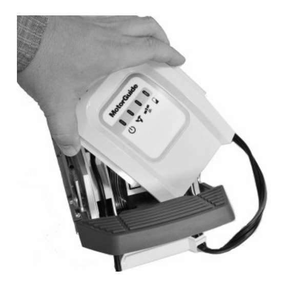
- Page 12 PRODUCT INSTALLATION AND OPERATION 8. Remove the status indicator light panel from the trolling motor by lifting it up, then rotating it to clear the foot release lever. Do not unplug the status indicator light panel from the trolling motor. 54527 9.
- Page 13 PRODUCT INSTALLATION AND OPERATION Remove the plastic plug, and route the GPS cable through the opening in the trolling motor base. Status light indicator panel Status light harness NMEA cable Female GPS connector Male GPS connector Lower GPS module GPS cable 53470 10.
- Page 14 PRODUCT INSTALLATION AND OPERATION 11. Install the side panels onto the trolling motor. Ensure that the status indicator light panel is seated between the side panels as shown, and that no wires are pinched. 54529 Status indicator light panel not seated—incorrect Status indicator light panel seated between side panels—correct 12.
- Page 15 PRODUCT INSTALLATION AND OPERATION 2. Within ten seconds after connecting the power cables, press the left arrow button and right arrow button on the handheld remote at the same time. The trolling motor will emit a low tune to confirm that the handheld remote has been linked to the trolling motor.
- Page 16 COMPASS CALIBRATION IMPORTANT: This calibration is completed at the factory. It should only be repeated if the Pinpoint GPS system is not responding properly. This calibration must be done with the boat in the water, using the primary propulsion engine.
-
Page 17: Operating The Pinpoint Gps System
To reset the trolling motor to the factory calibration, press and hold the manual mode button, then press 1, 1, 4. Operating the Pinpoint GPS System PINPOINT GPS STARTUP The global positioning system (GPS) is a satellite‑based navigation system capable of providing positional information anywhere on Earth, provided that the GPS receiver has a clear line of sight to at least four GPS satellites. - Page 18 PRODUCT INSTALLATION AND OPERATION When the trolling motor is powered up and deployed, it is immediately capable of operating as a conventional trolling motor. The trolling motor will require approximately 30 seconds to acquire a fixed GPS position. Having a clear view of the sky overhead, with no large trees, power lines, bridges, or buildings to interfere with the GPS signal, will improve the GPS accuracy and reduce the amount of time required to obtain a fixed GPS position.
- Page 19 In order for anchor mode to operate, the Pinpoint GPS system must have achieved a fixed GPS location, indicated by the trolling motor emitting a three‑beep tune, and the GPS status...
- Page 20 WARNING Avoid serious injury from colliding with other boats, running aground, or striking objects in the water. The Pinpoint GPS system cannot detect other boats, shallow water, or objects in the water. Always beware of possible obstructions to navigation when operating in any Pinpoint GPS mode.
- Page 21 PRODUCT INSTALLATION AND OPERATION Adjusting the Anchor Position 54151 Left turn—"jog" left Increase speed—"jog" ahead Right turn—"jog" right Decrease speed—"jog" behind Once the trolling motor is in anchor mode, the anchor position can be adjusted by pressing any of the four buttons indicated above. Pressing the left turn, right turn, increase speed (+), or decrease speed (–) buttons once will adjust the anchor position by five feet in the direction selected, relative to the boat's heading.
- Page 22 PRODUCT INSTALLATION AND OPERATION Storing or Overwriting an Anchor Position Memory buttons (1–8) 54420 NOTE: An anchor position can be stored or overwritten from any operating mode except route record mode. To store an anchor location, press and hold any of the numbered memory buttons for two seconds.
- Page 23 WARNING Avoid serious injury from colliding with other boats, running aground, or striking objects in the water. The Pinpoint GPS system cannot detect other boats, shallow water, or objects in the water. Always beware of possible obstructions to navigation when operating in any Pinpoint GPS mode.
- Page 24 WARNING Avoid serious injury from colliding with other boats, running aground, or striking objects in the water. The Pinpoint GPS system cannot detect other boats, shallow water, or objects in the water. Always beware of possible obstructions to navigation when operating in any Pinpoint GPS mode.
- Page 25 WARNING Avoid serious injury from colliding with other boats, running aground, or striking objects in the water. The Pinpoint GPS system cannot detect other boats, shallow water, or objects in the water. Always beware of possible obstructions to navigation when operating in any Pinpoint GPS mode.
- Page 26 PRODUCT INSTALLATION AND OPERATION Storing and Overwriting a Route A route can be stored from any mode by pressing the route record button. The trolling motor will emit a tune when the route record button is pressed. Once the route record button is pressed, begin navigating along your desired course. You can switch between manual mode and heading lock mode at any time while recording a route.
- Page 27 WARNING Avoid serious injury from colliding with other boats, running aground, or striking objects in the water. The Pinpoint GPS system cannot detect other boats, shallow water, or objects in the water. Always beware of possible obstructions to navigation when operating in any Pinpoint GPS mode.
- Page 28 WARNING Avoid serious injury from colliding with other boats, running aground, or striking objects in the water. The Pinpoint GPS system cannot detect other boats, shallow water, or objects in the water. Always beware of possible obstructions to navigation when operating in any Pinpoint GPS mode.
- Page 29 PRODUCT INSTALLATION AND OPERATION SELECTING THE AUDIO MODE The Pinpoint GPS system has three user‑selectable audio modes to choose from. These audio modes provide audible confirmation of selected modes, speeds, and button selections. Manual mode #1 button #2 button #3 button...
- Page 30 PRODUCT INSTALLATION AND OPERATION Audio Audio Mode 1 Audio Audio Condition Pattern (Default) Mode 2 Mode 3 Speed – (when greater Short beep – – than speed level 0) Speed – (at speed 0) 2 beeps – Pressing the propeller on/off button to turn the 2 beeps up –...
-
Page 31: Frequently Asked Questions And Troubleshooting
Finally, check the battery in the handheld remote and replace it if necessary. The Pinpoint GPS will not store an anchor point, recall a route, or hold a heading lock. Why is that? The GPS has not acquired a fixed GPS position. Allow at least 60 seconds for the GPS system to acquire a fixed GPS position. -
Page 32: Service Assistance
Service Assistance Your satisfaction with your product is very important to us. If you have a problem or question about your motor, contact your dealer or any certified MotorGuide Service Center. For more service assistance information, refer to Warranty Information. - Page 33 OWNER SERVICE ASSISTANCE Japan Telephone 072‑233‑8888 Kisaka Co., Ltd. 4-130 Kannabecho Sakai-shi Sakai-ku 5900984 Osaka, 072‑233‑8833 Japan Asia, Singapore Telephone (65) 65466160 Brunswick Asia Pacific Group T/A Mercury Marine Singapore Pte Ltd 29 Loyang Drive (65) 65467789 Singapore, 508944...
Need help?
Do you have a question about the Pinpoint and is the answer not in the manual?
Questions and answers