
Related Manuals for Spacelabs 90217


Summary of Contents for Spacelabs 90217
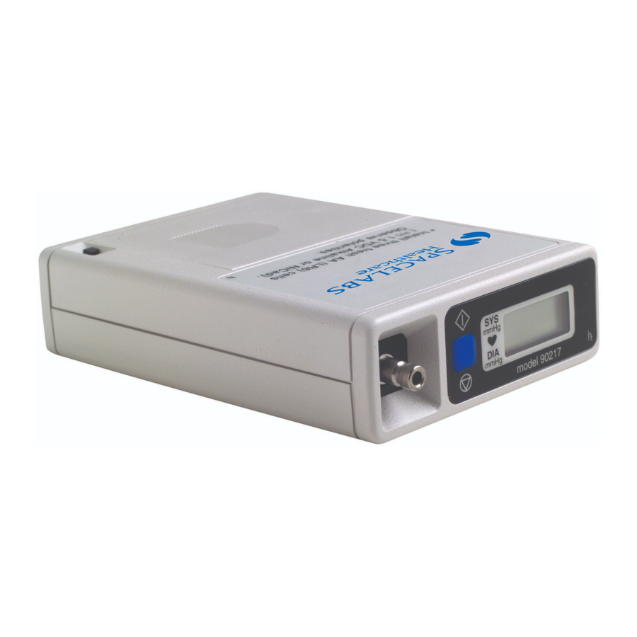
- Page 1 Ambulatory Blood Pressure Monitor 90217/90217Q Service Manual 070-0502-00 Rev. F more time to care...
- Page 2 © 2004 Spacelabs Medical, Inc. All rights reserved. Contents of this publication may not be reproduced in any form without the written permission of Spacelabs Medical. Products of Spacelabs Medical are covered by U.S. and foreign patents and/or pending patents. Printed in U.S.A.
-
Page 3: Table Of Contents
90217 Field Replaceable Parts Lists ........ -
Page 5: Introduction
(FT1000A/FT2000A or equivalent), a PC Interface, a Base Station, or a Report Generator for data analysis, report printing, and archiving. The 90217 monitor is housed in a plastic case with a removable battery cover that provides access to its three AA cells. Inside the monitor are three printed circuit boards: the Main, Power, and Display boards. -
Page 6: User Controls
(refer to the 90207, 90217 Ambulatory Blood Pressure Monitors Operations Manual, P/N 070-0137-xx). Display The monitor display is a 4-digit LCD that presents the following information (refer to the 90217 Ambulatory Blood Pressure Monitors, Operations Manual (P/N 070-0137-xx) for instructions on use). -
Page 7: Programming Options
Ambulatory Blood Pressure Monitor 90217 Service Manual Time of Day A real-time clock provides the time of day, which appears between measurement cycles and can be programmed in either a 12- or 24-hour mode. Cuff Pressure This pressure can be shown while the monitor is taking a measurement. If cuff pressure is not selected, “----”... - Page 8 Ambulatory Blood Pressure Monitor 90217 Service Manual Office Check Mode This mode verifies monitor operation and allows a user to view cuff pressure and blood pressure results regardless of any previous disabling of the display. During Office Check Mode, the monitor bleeds an additional pressure step below diastole.
-
Page 9: Setup
Operational Tests ........... . 7 Installing the Batteries Two types of batteries are used in the 90217 ABP Monitor: three standard AA batteries (Spacelabs Medical P/N 146-5011-xx) to power the cuff air pump, and one rechargeable lithium battery to backup the clock and RAM circuits when the AA batteries are removed or are exhausted. -
Page 10: Initializing The Monitor
Ambulatory Blood Pressure Monitor 90217 Service Manual 4 After correctly inserting the batteries, gently slide the battery cover back into place. 5 Switch the monitor ON and verify that the display appears. If there is no display, switch the monitor OFF and refer to in this manual. When power is first switched ON, the first four digits of the RAM code revision are displayed for about 1 second, followed by a blanked display, followed by the last two digits of the revision number. - Page 11 PHONE Note: The initialization procedure is provided in the 90219 Ambulatory Blood Pressure PC Direct/Base Station Operations Manual (P/N 070-0238-xx). 1 The 90217 can use one of the following modems for communication: • Hayes Smartmodem 1200 • Hayes Optima 9600 or equivalent •...
- Page 12 Ambulatory Blood Pressure Monitor 90217 Service Manual The Hayes Smartmodem 1200, which attaches to the monitor, must be set up as follows: Setting at Switch # Monitor Site down down down down down 2 Connect the serial port cable (P/N 012-0096-xx) between the monitor and the modem.
- Page 13 Ambulatory Blood Pressure Monitor 90217 Service Manual Note: The modem link must be established within 45 seconds for the 90217. If this does not happen, switch the monitor OFF and return to step 1. 5 When the information transfer is complete, the ABP monitor beeps and voice communication is restored.
- Page 14 7 Contact established. 9 Not attempting to contact modem. Once contact has been established, the second digit from the left on the 90217 display indicates the baud rate of the connection. On high speed modems, the indicated speed refers to the connection between the ABP monitor and the modem.
-
Page 15: Operational Tests
Ambulatory Blood Pressure Monitor 90217 Service Manual Operational Tests Conduct the following procedures to verify proper operation of the 90217 ABP Monitor. Equipment Required • 90219-02 system • 90219-03 ABP Base Station software • Type AA alkaline batteries (3) •... - Page 16 If only one manometer is used, block off the unused hose. fitting 2 Close the squeeze bulb valve. 3 Turn ON the 90217 and press the START/STOP button. 4 Verify the following monitor response: •...
- Page 17 Ambulatory Blood Pressure Monitor 90217 Service Manual PC Interface Test Note: The PC Inferface Test is only applicable for use with a PC System that operates with the 90219 software. 1 Connect the system as illustrated: 2 Power ON all devices.
- Page 18 Y key (yes) 18 Remove the 90217 from the system and switch power OFF. 19 Remove one AA battery. 20 Wait one minute and reinstall the battery. 21 Switch ON 90217 power and verify that the time remained correct. 2-10...
-
Page 19: Theory
90217 Block Diagram ........ -
Page 20: Oscillometric Amplifier
Ambulatory Blood Pressure Monitor 90217 Service Manual Oscillometric Amplifier Gain, Offset, and Filtering The oscillometric amplifier is DC coupled. A D/A converter provides large amounts of DC offset to the amplifier to prevent the large static pressure component of the waveform from over driving the amplifier. - Page 21 The watch dog timers ensure that the cuff cannot remain inflated because of a software crash. There are two watch dog timers in the Model 90217: one resides inside the processor; the other inside the real-time clock. Each counts 180 seconds before timing out. Both timers start at converter power up.
-
Page 22: 90217 Block Diagram
Ambulatory Blood Pressure Monitor 90217 Service Manual 90217 Block Diagram... -
Page 23: Digital Circuitry
Ambulatory Blood Pressure Monitor 90217 Service Manual Digital Circuitry Display Board Information is sent from the processor to the LCD controller via a serial bus (CBUS). The LCD controller activates the necessary segments to display information on the 4-segment LCD. Each of the segments can be controlled separately. -
Page 24: Unit Power
Ambulatory Blood Pressure Monitor 90217 Service Manual Unit Power All power for the 90217 ABP Monitor comes from the main batteries (3 AA cells) and the rechargeable 3-volt lithium battery. Unregulated Power Supplies +VSW The switched battery voltage (+VSW) is provided by the main batteries via the unit power switch. - Page 25 Ambulatory Blood Pressure Monitor 90217 Service Manual +5 VA Supply +5 VA is a secondary power source for the analog circuitry. It can be disconnected to reduce power consumption when the analog circuits are not being used by asserting the PWR_DWN line.
-
Page 26: Software Flow Chart
Ambulatory Blood Pressure Monitor 90217 Service Manual Software Flow Chart... -
Page 27: Maintenance
Maintenance Contents Cleaning ............1 Calibration Check . - Page 28 Ambulatory Blood Pressure Monitor 90217 Service Manual Air Bladder Removal Air Bladder Reinstallation...
-
Page 29: Calibration Check
Ambulatory Blood Pressure Monitor 90217 Service Manual Calibration Check To verify calibration of the 90217 ABP Monitor: 1 Obtain a full-size mercury sphygmomanometer (manometer) or aneroid gauge. 2 Disconnect the cuff hose from the monitor. 3 Connect the T-tube splitter to the monitor pneumatic connector and the sphygmomanometer. -
Page 30: Calibration Procedures
6 Disconnect the T-tube splitter from the monitor. Disconnect the air hose and sphygmomanometer from the T-tube. Re-connect the cuff to the monitor. Calibration Procedures The following procedures allow field testing and calibration of the Model 90217 ABP Monitor. Equipment Required •... - Page 31 Load the Production Test Aids software (Xmain.exe) onto the hard disk of the computer system • Copy the 90217 RAM code into same directory as Xmain.exe program (Production Test Aids software) • Ensure that charged batteries (3) are installed into the 90217 monitor Note: A voltimeter may be used to check battery condition.
- Page 32 Connect a DC voltmeter with the positive test lead on TP6 (+5 volts) and the negative on TP9 (ground). Verify that TP6 measures between +5.05 and +4.95 volts. If not, adjust R78 on the power board until TP6 measures +5.0 ±0.01 volts. 4 Replace the back cover of the 90217 case (removed in step 1).
- Page 33 Calibration Setup 1 Verify that the IR cable is connected to the serial port on the computer system and to the IR port on the back of the 90217 (when communicating correctly, the monitor will display 9999 and occasionally 2999).
- Page 34 Ambulatory Blood Pressure Monitor 90217 Service Manual Pressure Offset and Gain Adjustment 1 Adjust the pressure offset: From the Main Menu, select 5. SET 90217 GAIN AND OFFSET. Verify that the following screen appears: 90217 GAIN AND OFFSET ADJUSTMENT 1. Adjust offset pot for 00 with hose disconnected.
- Page 35 5 Subtract the first leakage rate (system leakage) from the second leakage rate (90217 + system leakage). 6 Verify that the pressure drop due to 90217 leakage is <6 mmHg per minute, or <4 mmHg per 4 minutes for 90217-41 (Japan) and <4 mmHg per 2 minutes for 90217-32 units (German).
-
Page 36: Operational Verification
6 When the valve opens (pressure decreases rapidly), verify that the elapsed time is between 178 and 182 seconds (fault holdoff timer). 7 When the 90217 display changes from showing pressure to showing the software version, verify that the elapsed time falls between 194 and 198 seconds (watch dog timer). - Page 37 Ambulatory Blood Pressure Monitor 90217 Service Manual 7 Perform a leak rate check on the blood pressure simulator and associated tubing as follows: While in the Main Menu, move the cursor to Press and select Leak Test by pressing ENT.
- Page 38 F1 key to select ADULT readings and then use the Esc key to increment to the reading desired. 13 Repeatedly press the START/STOP button on the 90217 to sequence through the list of blood pressures simulated by the CuffLink.
- Page 39 Ambulatory Blood Pressure Monitor 90217 Service Manual CuffLink Manual Operation The following steps outline the manual selection of simulated blood pressures and heart rates. These may be used to repeat a reading which was out of range or produced no reading.
-
Page 40: Manifold Kit - P/N 050-0110-Xx
To replace the manifold in the 90217 monitor: 1 Disassemble the 90217 ABP Monitor and remove the 672-0171-xx assembly. Separate the manifold from the rest of the assembly by cutting through the 176-0279-00 four-conductor flexstrip cable. Refer to Disassembly Procedures on page 4-15. -
Page 41: Disassembly Procedures
Ambulatory Blood Pressure Monitor 90217 Service Manual Disassembly Procedures Caution Observe precautions for handling electrostatic-sensitive devices! Note: • Never touch electrostatic-sensitive electronic components without following proper antistatic procedures, including the use of an ESD wrist band and mat. An electrostatic discharge from your fingers can permanently damage electronic components. -
Page 43: Troubleshooting
Monitor Event Codes The 90217 ABP Monitor displays a two-digit event code whenever it is unable to successfully complete a blood pressure measurement. This event code appears as the last digits on the monitor display and is preceded by the letters EC (for example, in the displayed event code EC01, 01 is the event code). - Page 44 Ambulatory Blood Pressure Monitor 90217 Service Manual EC48 Pulse pressure is less than historical pulse pressure minus 20 and many pulses failed either screen or failed match. EC50 No non-discarded entries at higher cuff pressures but within 16 mmHg of diastole.
-
Page 45: Base Station Report Event Codes
Ambulatory Blood Pressure Monitor 90217 Service Manual Base Station Report Event Codes The following list contains the extended event codes, which may appear in a blood pressure report. The extended event code digit appears in the first (tens) digit position (for example, 11). - Page 46 Monitor displays -- EC05 Base Station report prints: Equipment malfunction. Return it to Spacelabs Medical for service. Unit failed to initialize. Please re-initialize. At least one of the blood pressure or time readings obtained before the event code is erroneous.
-
Page 47: Problem Solving Checklist
Ambulatory Blood Pressure Monitor 90217 Service Manual Problem Solving Checklist Use this table to diagnose a monitor problem: Problem Possible Cause Solution Modem indicators are Modem switch settings are incorrect. incorrect. Check modem cable for tight Monitor display is incorrect. -
Page 49: Parts
90217 Field Replaceable Parts Lists ........ - Page 50 Ambulatory Blood Pressure Monitor 90217 Service Manual Table 2: Cuff Accessories Limb Part Number Part Number Description Circumference Quick-Disconnect Luer-Lock Pediatric Cuff 12 to 20 cm 015-0118-01Q 015-0118-01 Adult Cuff 17 to 26 cm 015-0067-01Q 015-0067-01 Adult Cuff 24 to 32 cm...
-
Page 51: Drawings
Ambulatory Blood Pressure Monitor 90217 Service Manual Label, Operating Instructions ....334-1107-00 Label, ID, Serial Number ..... 334-0922-00 German Label, Front Panel . -
Page 53: Symbols
Symbols The following list of international and safety symbols describes all symbols used on Spacelabs Medical products. No one product contains every symbol. Symbol Description Symbol Description HELP Key Keyboard Connection SPECIAL FUNCTIONS Key Mouse connection RECORD Key START/STOP Key... - Page 54 Ambulatory Blood Pressure Monitor 90217 Service Manual Symbol Description Symbol Description Stand-by STAND-BY Key PAUSE or INTERRUPT Slow Run Reset Power Indicator LED Temporary Shut Off of Alarm Tone Alarm or Screen Indicators Indicator — Remote Control Indicator — Local Control PRINT REPORT Key Indicator —...
- Page 55 Ambulatory Blood Pressure Monitor 90217 Service Manual Symbol Description Symbol Description Data Input/Output Input/Output Input Reset Menu Keys Waveform/Parameter Keys Monitor Setup Set Initial Conditions Menu Select Program Options Access Special Function Menu Return Unit to Monitor Mode Serial Port 1...
- Page 56 Ambulatory Blood Pressure Monitor 90217 Service Manual Symbol Description Symbol Description Open Padlock Closed Padlock Down Arrow Up Arrow Hard Drive Power Indicator LED Antenna Mermaid Connector Microphone Omnidirectional Microphone Audio Output, Speaker Activate Telemetry Recorder Network Connection Universal Serial Bus...
- Page 57 Ambulatory Blood Pressure Monitor 90217 Service Manual Symbol Description Symbol Description Protective Earth Ground Functional Earth Ground Replace Fuse Only as Marked Fuse Power supply jack polarity. Equipotentiality Terminal (+ / - signs may be reversed) Alternating Current Direct Current...
- Page 58 Ambulatory Blood Pressure Monitor 90217 Service Manual Symbol Description Symbol Description Canadian Standards Association ® ETL Laboratory Approved Approved Risk of Explosion if Used in the Operates on Non-Harmonized Presence of Flammable Anesthetics Radio Frequencies in Europe Attention - Consult Operations or...
- Page 59 Ambulatory Blood Pressure Monitor 90217 Service Manual Abbreviations used as symbols are shown below. Symbol Description Symbol Description Access Codes 1 - 32 1 Through 32 ANT 1 Diversity Antenna System 1 Arr1 Arrhythmia Net 1 ANT 2 Diversity Antenna System 2...
- Page 60 Ambulatory Blood Pressure Monitor 90217 Service Manual Symbol Description Symbol Description Temperature 1 Temperature 2 Systolic Temperature 3 Temperature 4 TEMP Temperature Uterine Activity or Umbilical Artery temp Vacuum Connection...
-
Page 61: Appendix A - Electromagnetic Compatibility
Frequency Separation Distances ........2 Electromagnetic Emissions Note: The 90217 ABP monitor has been tested under laboratory conditions and is suitable for use in all establishments, including domestic establishments and those directly connected to the public low-voltage power supply network that supplies buildings used for domestic purposes. -
Page 62: Frequency Separation Distances
90207 Ambulatory Blood Pressure Monitor Service Manual Frequency Separation Distances Note: The ABP monitor is intended for use in an electromagnetic environment in which radiated RF disturbances are controlled. The customer, or user, of the module can help prevent electromagnetic interference by maintaining a minimum distance between portable and mobile RF communications equipment (transmitters) and the module, as recommended below, according to the maximum output power of the communications equipment. - Page 63 90207 Ambulatory Blood Pressure Monitor Service Manual Rated Maximum Separation Distance According to Frequency of Transmitter Output Power of (meters) Transmitter 150 kHz to 80 MHz 80 MHz to 800 MHz 800 MHz to 2.5 GHz (watts) 0.01 0.02 0.02 0.04 0.06 0.06...
Need help?
Do you have a question about the 90217 and is the answer not in the manual?
Questions and answers
Visual display showing broken lines
Broken lines on the visual display of a Spacelabs 90217 typically indicate that no data was transferred. This may be due to incorrect switch settings or a loose modem or communications cable connection.
This answer is automatically generated