Table of Contents
Advertisement
Quick Links
Advertisement
Table of Contents

Subscribe to Our Youtube Channel
Related Manuals for Freefly M?VI Controller


Summary of Contents for Freefly M?VI Controller
- Page 1 U S E R GU I D E...
- Page 2 COMPATIBILITY The MōVI Controller is compatible with the MōVI M5, M10, and M15 running firmware version 3.08 or later. Download the latest MōVI firmware and update instructions at www.freeflysystems.com. See Follow-Focus Integration section for information on wireless lens control system compatibility.
-
Page 3: Controller Specifications
Power Level 4 +18 dBm Range Power Level 0 (EU), Outdoor Line-of-Sight 1200 ft / 300 m MŌVI CONTROLLER PHYSICAL: Weight Including Antenna, Excluding Monitor and Battery Plate 950 g Dimensions Including Antenna and Joystick, Excluding Monitor and Battery Plate... - Page 4 Once running firmware v3.08 or later, change the MōVI Radio Type from the default (DSMX 2048) to MōVI Controller. This can be done from any of the Freefly Configurator apps (PC, Mac, Android) in the Remote Controller Config menu.
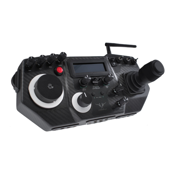
- Page 5 MōVI CONTROLLER LAYOUT Auxiliary Data 2.4 GHz Antenna Port (7-pin LEMO) 13-20V DC Input 2x USB Ports 12V DC Output MONITOR MOUNT / TRIPOD MOUNT (2-pin LEMO) ZOOM ROLL SPEED TILT SPEED DualOperator SPEED SPEED Majestic MODE USER 3 TILT DIRECTION...
-
Page 6: Receiver Layout
RECEIVER LAYOUT 2.4GHz Receiver Antenna Bind Button Channel Switch Firmware Update (FW) Button Status LED 3-pin Spektrum Remote Port 5-pin Mo o VI Data Port Shutter/Record Output Port... -
Page 7: Connectors And Pinouts
CONNECTORS AND PINOUTS 13-20V DC INPUT 12V DC OUTPUT 5.5mm OD 2-pin LEMO TYPE 2.1mm ID Barrel Jack Connector FGG.0B.302.CLAD52 12V DC OUTPUT, 3A MAX Center Positive e.g. CUI Inc PP3-002A (LOOKING IN TO CONTROLLER- SIDE CONNECTOR) AUXILIARY DATA PORT 7-pin LEMO TYPE 5V Output, 1A max. -
Page 8: Display Layout
MōVI. Connected: The MōVI is connected and running, and the MōVI Controller is receiving live telemetry. When the Mōvi acquires GPS lock, the GPS icon () is displayed and GPS-based acceleration compensation GPS STATUS: (to minimize horizon drift during high-acceleration movement) is active. -
Page 9: Menu Description
YPICAL CREEN TRANSMITTER BATTERY LEVEL: The state of charge of the MōVI Controller battery. See Power section for details on what batteries can be used with the MōVI Controller. MENU DESCRIPTION: A brief description of each menu accessible from the Home menu. - Page 10 MōVI CONTROLLER RECEIVER INSTALLATION: 5. Attach the Receiver to Remove the Spektrum Plug the other end of Remove adhesive backing Receiver and 3-pin cable the 5-pin cable into the from the Receiver. the Gimbal Controller (if applicable). MōVI Data port on the as shown.
- Page 11 RECEIVER STATUS LED The Receiver Status LED conveys information about the state of the radio link between the MōVI Controller and the MōVI: CONDITION NORMAL OPERATION WHILE BINDING No power. No power. FAST FLASHING GREEN Connection starting. Not used. SLOW FLASHING GREEN Connection started, waiting for data.
- Page 12 The MōVI Controller comes with a Receiver already bound to it and ready for communication with a MōVI. This MōVI Controller and Receiver form a bound pair. Only that specific MōVI Controller can control that Receiver. However, it is possible to rebind the Receiver to a new MōVI Controller, or bind new Receivers to a single MōVI Controller for working with multiple MōVI systems.
- Page 13 MōVI Controller Serial Number 0001 cannot control MōVI Serial Number 0003, because they have not been bound. Binding is the act of joining a Device Group of one particular MōVI Controller. For example, setting MōVI Controller Serial Number 0003 to Device Group 02 and binding MōVI Serial Number 0005 according to the bind process described above causes MōVI Serial Number 0005 to join that Device Group.
- Page 14 DC INPUT: The primary DC input is a 5.5mm O.D., 2.1mm I.D. center-positive barrel jack connector located on the back of the MōVI Controller. It is designed for a 15V power supply, but will accept voltages from 13V to 20V. It is reverse polarity protected up to 20V. However, supplying more than 20V will result in damage.
- Page 15 Transmitter uses the same hardware as the MōVI Controller Receiver and communicates directly with the follow-focus system. It connects to the Auxiliary Data Port on the MōVI Controller. The range of the Auxiliary Transmitter is similar to that of the primary radio link to the MōVI (approx. 1200ft outdoor/line-of-sight).
-
Page 16: Menu Structure
MENU STRUCTURE: HOME The Home menu is the starting point for navigating through other MōVI Controller menus. You can always return to the Home menu by scrolling to and clicking the Home icon in the top-left corner of the display. - Page 17 The Shutter/Record Output switches between active and inactive each time the Record Start/Stop Button is pressed. TOGGLE: RECORD POLARITY: Change the active state of the Shutter/Record Output signal from the MōVI Controller Receiver. The Shutter/Record Output is active high (3.3V digital output).
- Page 18 USER FUNCTION DESCRIPTION USER 1 USER 2 USER 3 NOTES None Default Default Default Pan Dir Reverse Pan/Tilt Joystick X-Axis (Pan). Threshold is 50% for USER 1 and USER 2 Focus Dir Reverse Focus Knob input. Threshold is 50% for USER 1 and USER 2 Zoom Dir Reverse Zoom Rocker input.
- Page 19 MōVI MONITOR Live telemetry from the MōVI is available in this menu. The first line displays MōVI run time since power-up, as well as the status of important MōVI systems: Compass (CMP), Global Positioning System (GPS), Motor Drive (DRV), and Inertial Measurement Unit (IMU). The Compass (CMP) and Global Positioning System (GPS) are used to minimize the effect of high acceleration on the MōVI’s tilt and roll axis stabilization.
-
Page 20: System Options
MōVI CONFIG SYSTEM OPTIONS Save MōVI configuration to non-volatile (long-term) memory from here. Settings changes not saved before powering down or rebooting the MōVI will be lost. SAVE SETTINGS: Reinitialize the MōVI. This can be useful for clearing any Errors that occur during MōVI start-up. REBOOT MōVI: These settings control how much the motors are used to stabilize the camera on each axis. - Page 21 Write the modified Channel, Device Group, or Power Level to the radio. WRITE: Add a new receiver to the current Device Group. This will allow the MōVI Controller to communicate with the new Receiver. See Binding to a New MōVI BIND:...
-
Page 22: Device Group
DEVICE GROUP can have one or more MōVI Controller Receivers bound to it. This can be useful for selecting between multiple MōVI systems that are on at the same time. For simple single MōVI use, the Device Group can be left at the default setting (0). -
Page 23: Radio Mode
MōVI Controller Receiver. The channel mapping in DSMX 2048 mode is shown below. In this mode, the MōVI Controller relays raw data between the Receiver and a host computer via USB. This can be used to control the MōVI from a computer TETHER/RX FW: interface, or to update the Receiver firmware. -
Page 24: Mounting To A Tripod
1/4-20 threaded holes and rotate the tripod head to the desired angle. The heat sink located on the back of the controller has a 1/4-20 thread that can be used to mount the MōVI Controller to a tripod when an HEAT SINK: IDX plate is not attached. -
Page 25: Troubleshooting
Channel 1 thru C: < 5 seconds Channel 0 (Auto): < 15 seconds The MōVI Controller and Receiver are on different Set the Receiver to the same channel as the MōVI Controller channels. (Radio Config::Channel), or to Channel 0 (Auto). - Page 26 POSSIBLE CAUSE SOLUTION Bind Failed. MōVI Controller was not detected. Make sure the MōVI Controller is powered on and in range. Turn off any other MōVI Controller that might be in range. Receiver Status LED: (Slow-Flashing Red) OR Radio Config::Radio Action::Bind to permit binding after MōVI Controller did not allow binding.
- Page 27 AUXILIARY TRANSMITTER: The MōVI Controller Receiver can optionally be used as an Auxiliary Transmitter for controlling third-party wireless follow-focus systems. For more information on supported systems, see the Follow-Focus Integration section. To change modes: Move the Receiver Channel Switch to the position indicated in the table below.
-
Page 28: Firmware Update
The MōVI Controller Receiver included with the MōVI Controller is configured in MōVI Controller Receiver mode by default. It can be changed to an Auxiliary Transmitter mode if necessary by following the instructions above. Auxiliary Transmitters purchased separately for follow-focus integration will be preconfigured in either microRemote Auxiliary Transmitter mode or Axis 1 Auxiliary Transmitter mode depending on the option selected at purchase. -
Page 29: Europe (Etsi)
CERTIFICATIONS: The MōVI Controller transmitter and receiver contain radio modules and antennas that are certified for use internationally. The following agency certifications apply: FCC: Contains FCC ID: OUR-XBEEPRO CANADA (IC): Contains Model XBee-PRO Radio, IC: 4214A-XBEEPRO EUROPE (ETSI): Radio module conforms to CE requirements.
Need help?
Do you have a question about the M?VI Controller and is the answer not in the manual?
Questions and answers