
Subscribe to Our Youtube Channel
Related Manuals for MGE UPS Systems Pulsar EXtreme 1500


Summary of Contents for MGE UPS Systems Pulsar EXtreme 1500
- Page 1 Pulsar EXtreme installation and user manual 1500/2000/2500/3000 VA - Page 1 51033211EN/AA...
- Page 2 Pulsar EXtreme at the end of its service life. To discover the entire range of MGE UPS SYSTEMS products and the options available for the Pulsar EXtreme range, we invite you to visit our web site at Erreur! Signet non défini. or contact your MGE UPS SYSTEMS representative.
-
Page 3: Safety Rules
Safety Safety rules Safety of persons A UPS has its own internal power source (the battery). Consequently, the power outlets may be energized even if the UPS is disconnected from the AC-power source. Dangerous voltage levels are present within the UPS. It should be opened exclusively by qualified service personnel. - Page 4 Foreword Using this document Information may be found primarily by consulting: the contents; the index. Pictograms Important instructions that must always be followed. Information, advice, help. Visual indication. Action. Audio indication. In the illustrations on the following pages, the symbols below are used: LED off.
-
Page 5: Table Of Contents
Contents Presentation Pulsar EXtreme range ......................... 7 Tower model ............................ 7 Rack model ............................. 7 Connection modules ........................8 Fault tolerant ........................... 8 Hot swap ............................8 Install ............................... 8 Back ............................. 9 Control panel ..........................10 Installation Unpacking and checks ....................... 11 "Tower"... - Page 6 Contents Failure of AC input power and operation on battery power ............ 20 Transfer to battery power ......................20 Threshold for the low-battery shutdown warning ................20 End of backup time ........................20 Sleep mode ........................... 20 Return of AC input power ......................20 Personalization ...........................
-
Page 7: Presentation
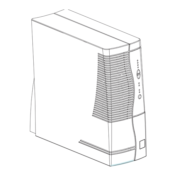
1. Presentation 1.1 Pulsar EXtreme range Tower model Dimensions in mm (H x W x D) EXtreme 1500 to 3000 443 x 173 x 465 Weight in kg EXtreme 1500 to 2000 EXtreme 2500 to 3000 Rack model Dimensions in mm (H x W x D) EXtreme 1500 to 3000 177 (4U) x 483 x 462... -
Page 8: Connection Modules
1. Presentation 1.2 Connection modules Fault tolerant socket for connection to AC-power source. outlets for direct connection to protected equipment. manual bypass switch. input terminal block with cable clamp. output terminal block with cable clamp. Hot swap Install Page 8 - 51033211EN/AA... -
Page 9: Back
1. Presentation 1.3 Back slot for communications-card option. battery module connector. battery circuit breaker. rating plate. connector for connection modules. RS232 communications port. - Page 9 51033211EN/AA... -
Page 10: Control Panel
1. Presentation 1.4 Control panel Alarms % battery % load remaining UPS overload 100% 100% electronics fault battery fault ambient temp. > 40°C hold down to display percent load. lamp test or buzzer OFF. operation on manual bypass. operation in ECO mode. operation in ON-LINE mode. -
Page 11: Unpacking And Checks
2. Installation 2.1 Unpacking and checks Tower model RS 232 communications cable. "Solution Pac" CD ROM. "UPS Driver" diskette for UPS personalization. documentation. electrical power cord (except INSTALL version). - Page 11 51033211EN/AA... - Page 12 2. Installation Rack model RS 232 communications cable. "Solution Pac" CD ROM. "UPS Driver" diskette for UPS personalization. documentation. electrical power cord (except INSTALL version). telescopic rails for mounting in 19" bay with mounting hardware. Page 12 - 51033211EN/AA...
- Page 13 2. Installation 2.2 Installation (rack version) Rack mounting diagram with rails. The rails and the necessary mounting hardware are supplied with the UPS in the package. - Page 13 51033211EN/AA...
-
Page 14: Connection To The Rs 232 Communications Port (Optional)
2. Connect the RS 232 communications cable to the RS 232 communications port on the UPS. The UPS can now communicate with all MGE UPS SYSTEMS supervision, set-up or safety software. Pin-out diagram for the RS 232 communications port on the UPS. -
Page 15: Securing And Connecting The Connection Modules
2. Installation 2.5 Securing and connecting the connection modules Securing the connection modules 1. Insert the connection module in the connector 2. Secure the connection module to the UPS using the two screws Fault tolerant Before carrying out any connections, check that the battery circuit breaker is OFF and that the electrical power cord to the AC-power source is disconnected. -
Page 16: Hot Swap
2. Installation Hot swap Before carrying out any connections, check that the battery circuit breaker is OFF and that the electrical power cord to the AC-power source is disconnected. Connection of equipment to outlets Plug your equipment into the outlets Connection of equipment to a terminal block: This type of connection must be carried out by qualified electrical personnel. -
Page 17: Install
2. Installation Install This type of connection must be carried out by qualified electrical personnel. Before carrying out any connections, check that the battery circuit breaker is OFF and that the upstream protection devices (AC distribution system) are open (OFF). The overall cable diameter and the cross-sectional area of the three wires depends on the UPS rating. -
Page 18: Operating Mode
3. Operation 3.1 Operating mode ON-LINE mode This is the standard operating mode, set by default in the factory. It makes use of electronic double conversion of the input power. Two possible cases: is ON: AC input power is available. Power is drawn from the distribution system and supplied to the protected equipment via the UPS. -
Page 19: Start-Up
3. Operation 3.2 Start-up The protected equipment connected to the UPS can be energized, whether AC input power is available or not. Prior to initial start-up, check the UPS voltage settings. If the protected equipment voltage is other than 230 V / 50 Hz, the UPS settings must be modified using the "UPS Driver" software (see section 3.5). -
Page 20: Failure Of Ac Input Power And Operation On Battery Power
3. Operation 3.4 Failure of AC input power and operation on battery power AC input power is not available, the battery steps in to supply the protected equipment. Transfer to battery power The AC-power source is outside tolerances, LED is ON, the buzzer beeps three times. -
Page 21: Personalization
3. Operation 3.5 Personalization Function Personalization parameters can be set and modified using the "UPS Driver" software installed on a computer that is connected to the UPS (see section 2.3 Connection to the RS 232 communications port). Check that the RS 232 cable is correctly connected and that the battery circuit breaker is closed. -
Page 22: Battery" Tab
3. Operation "Battery" tab Personalizable function Default setting Options Once a week "Battery test" intervals Every day Once a month No test "Low-battery shutdown warning" threshold 20% remaining battery 40% remaining battery backup time backup time Charger Standard CLA (2, 4 or 8 hours) "Output"... -
Page 23: Eco Mode" Tab
3. Operation "ECO mode" tab ECO mode is not possible unless it has first been authorized using the "UPS Driver" software Personalizable function Default setting Options ECO mode authorization Disabled Enabled (click to check) (not authorized) The upper threshold (max. voltage) is between the maximum authorized voltage for transfer to Authorized voltage range for 200 V to 240 V... -
Page 24: Maintenance Troubleshooting
4. Maintenance 4.1 Troubleshooting If any of LEDs 14 15 16 flash, there is a operating anomaly or an alarm. If a LED flashes, the bargraph data is no longer displayed. Troubleshooting not requiring MGE after-sales support Indication Signification Correction flashes and the buzzer UPS overload. - Page 25 4. Maintenance Troubleshooting requiring MGE after-sales support Indication Signification Correction flashes and the buzzer UPS electronics have detected a UPS For UPSs equipped with Hot beeps. fault. swap or Install connection Depending on the UPS personalization modules, follow the UPS parameters (see section 3.5), there are replacement procedure (see two possibilities:...
-
Page 26: Ups Replacement
4. Maintenance 4.2 UPS replacement Fault-tolerant connection module Before carrying out this operation, the supply of power to the connected equipment must be cut. Disconnection: 1. Shut down the UPS by pressing button (return to the OFF position). 2. Open the battery circuit breaker(s) 3. -
Page 27: Hot-Swap And Install Connection Modules
4. Maintenance Hot-swap and Install connection modules Disconnection: Before turning the switch, see the manual 1. Turn the manual bypass switch from the NORMAL to the intermediate position. 2. Check that LED is ON before continuing to the BYPASS NORMAL BY-PASS position. -
Page 28: Environment
It was manufactured in a factory certified ISO 14001. UPS recycling at the end of service life: MGE UPS SYSTEMS undertakes to recycle, by certified companies and in compliance with all applicable regulations, all UPS products recovered at the end of their service life (contact your branch office). -
Page 29: Glossary
6. Appendices 6.1 Glossary Authorized voltage The range of voltage supplied by the AC-power source within which the UPS range for operation can operate in ECO mode. In ECO mode, the equipment connected to the in ECO mode UPS is supplied directly by the AC-power source, via the automatic bypass. Authorized voltage Upper and lower voltage thresholds within which the UPS can operate range for transfer to... - Page 30 6. Appendices Frequency-regulation rate The rate at which the UPS frequency is synchronized with that of the AC-power source. Two possible cases: 1. The installation comprises a single UPS. The frequency-regulation rate is set to "Standard". 2. The installation comprises two UPSs connected in series. The AC-power source supplies power to the first UPS which in turn supplies the second UPS.
-
Page 31: Index
6. Appendices 6.2 Index AC power LEDs Failure ............20 Lamp test ............10 Frequency tolerance ........22 Rated frequency ..........22 Rated voltage ..........22 Mode Return ............20 ECO mode .......... 10-18-23 ON LINE mode ......... 10-18 Bargraph .............. 19 Battery Overload ............ - Page 32 SYSTEMS N o t h i n g w i l l s t o p y o u n o w 140, Avenue Jean Kuntzmann ZIRST - Montbonnot St Martin 38334 - ST ISMIER CEDEX - FRANCE www.mgeups.com 51033211EN/AA Page 32 - 51033211EN/AA...
- Page 33 Pulsar EXtreme Installations- und Bedienungsanleitung 1500/2000/2500/3000 VA - Page 1 51033211DE/AA...
- Page 34 Einleitung Wir danken Ihnen, daß Sie sich für ein Produkt von MGE UPS SYSTEMS zum Schutz Ihrer Anwendungen entschieden haben. Die Baureihe Pulsar EXtreme wurde mit größter Sorgfalt entwickelt. Um die Leistungen Ihrer USV (Unterbrechungsfreien Stromversorgung) optimal nutzen zu können, empfehlen wir Ihnen, sich ein wenig Zeit zu nehmen und das vorliegende Handbuch aufmerksam zu lesen.
- Page 35 Sicherheit Sicherheitsregeln Personenschutz Die USV verfügt über eine eigene interne Energiequelle (Batterie). Die Abgangssteckdosen können daher unter Spannung stehen, selbst wenn die USV vom Leitungsnetz getrennt ist. Gefährliche Spannung im Innern der USV. Öffnen des Gehäuses darf nur durch Fachpersonal erfolgen.
- Page 36 Vorbemerkungen Aufbau der Installations- und Bedienungsanleitung Die Suche nach bestimmten Informationen erfolgt auf einfachste Weise: über das Inhaltsverzeichnis, über das Stichwortregister. Bedeutung der Piktogramme WICHTIG, Hinweise unbedingt befolgen Informationen, Ratschläge, Hilfen Optische Anzeige Maßnahmen, Handlungen Akustischer Alarm In den Abbildungen der nachfolgenden Seiten sind die LED-Anzeigen mit folgenden Symbolen dargestellt: LED AUS LED AN LED blinkt...
- Page 37 Inhalt Ansichten und Beschreibung Die Baureihe Pulsar EXtreme ....................7 Tower-Modell ........................... 7 Rack-Modell ............................ 7 Anschlußmodule ......................... 8 Fault tolerant Modul ........................8 Hot Swap Modul ..........................8 Install Modul ............................ 8 Rückansicht ..........................9 Anzeige- und Bedienfeld ......................10 Aufstellung und Installation Entfernen der Verpackung und Überprüfung des Lieferumfangs ..........
- Page 38 Inhalt Batterieversorgung der Verbraucher bei Netzausfall .............. 20 Umschaltung auf Batteriebetrieb ....................20 Voralarm "Ende der Autonomiezeit" ....................20 Abschaltung am Ende der Autonomiezeit ..................20 Sleep-Modus ..........................20 Rückkehr der Netzspannung ......................20 Kundenspezifische Anpassung per Software ................21 Software, Installation und Funktion ....................
-
Page 39: Ansichten Und Beschreibung
1. Ansichten und Beschreibung 1.1 Die Baureihe Pulsar EXtreme Tower-Modell Abmessungen in mm (H x B x T) EXtreme 1500 bis 3000 443 x 173 x 465 Gewicht in kg EXtreme 1500 bis 2000 EXtreme 2500 bis 3000 Rack-Modell Abmessungen in mm (H x B x T) EXtreme 1500 bis 3000 177 (4U) x 483 x 462... -
Page 40: Anschlußmodule
1. Ansichten und Beschreibung 1.2 Anschlußmodule Fault tolerant Modul Netzanschluß Steckdosen für Verbraucherabgänge Handumgehungsschalter Eingangs-Klemmenanschlüsse mit Kabeleinführung Ausgangs-Klemmenanschlüsse mit Kabeleinführung Hot Swap Modul Install Modul Page 8 - 51033211DE/AA... -
Page 41: Rückansicht
1. Ansichten und Beschreibung 1.3 Rückansicht Steckplatz für Kommunikationskarte (Option) Steckverbinder zum Anschluß eines externen Batteriemoduls Batterie-Leistungsschalter Typenschild Steckverbinder für Anschlußmodule RS232-Kommunikationsschnittstelle - Page 9 51033211DE/AA... -
Page 42: Anzeige- Und Bedienfeld
1. Ansichten und Beschreibung 1.4 Anzeige- und Bedienfeld Anzeige- und % Restauto- % Auslastungs- Bedieneinheiten nomiezeit grad Überlast 100% 100% interne USV-Störung Batteriestörung Umgebungstemperatur > 40°C Auslastungsgrad (Taste gedrückt halten): Taster LED-Test und Summerabschaltung Betrieb über Handumgehung ECO-Mode ONLINE-Mode Batteriebetrieb Ein/Aus-Taster (ON/OFF) Page 10 - 51033211DE/AA... -
Page 43: Aufstellung Und Installation
2. Aufstellung und Installation 2.1 Entfernen der Verpackung und Überprüfung des Lieferumfangs Tower-Modell Verbindungskabel für RS232-Kommunikationsschnittstelle CD ROM mit USV-Software Solution-Pac Diskette mit Software UPS Driver zur kundenspezifischen Anpassung der USV Dokumentation Netzkabel (außer bei FESTINSTALLATIONS-Version) - Page 11 51033211DE/AA... -
Page 44: Rack-Modell
2. Aufstellung und Installation Rack-Modell Verbindungskabel für RS232-Kommunikationsschnittstelle CD ROM mit USV-Software Solution-Pac Diskette mit Software UPS Driver zur kundenspezifischen Anpassung der USV Dokumentation Netzkabel (außer bei FESTINSTALLATIONS-Version) Teleskopschienen und Schraubenmaterial für Einbau in 19"-Schränke Page 12 - 51033211DE/AA... -
Page 45: Einbau Des Rack-Modells
2. Aufstellung und Installation 2.2 Einbau des Rack-Modells Einbau und Befestigung der Teleskopschienen und der Rack. Befestigungsschrauben und Teleskopschienen liegen dem Gerät bei. - Page 13 51033211DE/AA... -
Page 46: Anschluß Des Rs232-Kommunikationskabels (Wahlweise)
2. Aufstellung und Installation 2.3 Anschluß des RS232-Kommunikationskabels (wahlweise) 1. Kommunikationskabel an die serielle Schnittstelle des zu schützenden Systems anschließen. 2. Kommunikationskabel an die RS232-Schnittstelle USV anschließen. Die USV kann nun über verschiedene Softwarepakete von MGE UPS SYSTEMS mit dem angeschlossenen Rechnersystem kommunizieren (Überwachung, Konfiguration, Sicherheitsparameter). -
Page 47: Montage Der Anschlußmodule
2. Aufstellung und Installation 2.5 Montage der Anschlußmodule Befestigung der Anschlußmodule 1. Anschlußmodul auf den Steckverbinder aufstecken. 2. Anschlußmodul mit 2 Schrauben an der USV befestigen. Fault tolerant Modul Vor dem Anschluß ist sicherzustellen, daß der Batterie-Leistungsschalter 8 in OFF-Stellung steht und das Netzkabel nicht angeschlossen ist. -
Page 48: Hot-Swap Modul
2. Aufstellung und Installation Hot-Swap Modul Vor dem Anschluß ist sicherzustellen, daß der Batterie-Leistungsschalter in OFF-Stellung steht und das Netzkabel nicht angeschlossen ist. Anschluß der Verbraucher über Abgangssteckdosen: Verbraucher direkt an die Abgangssteckdosen anschließen. Anschluß der Verbraucher über Klemmleiste: Dieser Anschluß darf nur von qualifiziertem Fachpersonal durchgeführt werden. -
Page 49: Install Modul
2. Aufstellung und Installation Install Modul Dieser Anschluß darf nur von qualifiziertem Fachpersonal durchgeführt werden. Vor dem Anschluß ist sicherzustellen, daß der Batterie-Leistungsschalter in OFF-Stellung steht und die netzseitigen Schutzorgane ausgeschaltet sind. Kabeldurchmesser und Leiterquerschnitte hängen von der Nennleistung der USV ab. Kabeldurchmesser Leiterquerschnitt (mm) -
Page 50: Betriebszustände
3. Betriebszustände 3.1 Betriebsarten ONLINE-Mode Diese Betriebsart ist werksseitig voreingestellt. Dabei arbeitet die USV nach dem Doppelwandlerprinzip. Es können zwei Betriebszustände vorliegen: leuchtet: Das Einspeisenetz ist vorhanden (Normalbetrieb). Das Einspeisenetz versorgt über die USV die Verbraucher. leuchtet: Das Einspeisenetz ist nicht vorhanden (Batteriebetrieb). -
Page 51: Inbetriebnahme Der Usv
3. Betriebszustände 3.2 Inbetriebnahme der USV Die an die USV angeschlossenen Verbraucher können unabhängig vom Vorhandensein des Einspeisenetzes eingeschaltet werden. Vor dem ersten Einschalten der USV ist die Einstellung der Netzspannung zu überprüfen. Werden die Verbraucher nicht mit 230 V / 50 Hz eingespeist, müssen die entsprechenden USV- Parameter über die Software "UPS Driver"... -
Page 52: Batterieversorgung Der Verbraucher Bei Netzausfall
3. Betriebszustände 3.4 Batterieversorgung der Verbraucher bei Netzausfall Bei Netzausfall werden die an die USV angeschlossenen Verbraucher unterbrechungsfrei über die Batterie weiter versorgt. Umschaltung auf Batteriebetrieb Das Einspeisenetz liegt außerhalb der zulässigen Toleranzen, die Anzeige leuchtet auf und der Summer erzeugt 3 Pieptöne. -
Page 53: Kundenspezifische Anpassung Per Software
3. Betriebszustände 3.5 Kundenspezifische Anpassung per Software Software, Installation und Funktion Die kundenspezifische Anpassung der USV kann mit Hilfe der Software "UPS Driver" über einen Rechner erfolgen, der über die serielle Kommunikationsschnittstelle mit der USV verbunden ist (siehe Abschnitt 2.3). Das RS232-Kommunkationskabel muß... -
Page 54: Registerkarte "Batterie
3. Betriebszustände Registerkarte "Batterie" Mögliche Einstellwerte Einstellungen Default-Einstellung einmal wöchentlich einmal monatlich Zeitintervall für Batterietest täglich kein Test 40% Restautonomiezeit Grenzwert Voralarm "Ende der Autonomiezeit" 20% Restautonomiezeit Ladegerät Standard CLA (2, 4 oder 8 Std.) Registerkarte "Ausgang" Nennspannung des Einspeisenetzes (Abb. 1) 230 V 200 V-208 V-220 V-240 V Nennfrequenz des Einspeisenetzes... -
Page 55: Registerkarte "Eco-Mode
3. Betriebszustände Registerkarte "ECO-Mode" Der ECO-Mode kann nur über die Software "UPS Driver" eingestellt werden. Einstellungen Default-Einstellung Mögliche Einstellwerte Freigabe des ECO-Mode keine Freigabe freigegeben (unzulässig) (Optionsfeld anklicken) Oberer Grenzwert zwischen Höchstwert der Spannung für Umschaltung auf NRE Zulässiger Spannungsbereich 200 V –... -
Page 56: Wartung Und Service
4. Wartung und Service 4.1 Fehlerbehebung Das Blinken einer der LEDs oder zeigt eine Betriebsstörung oder einen Alarmzustand an. Sobald eine der LEDs blinkt, ist die Balkenanzeige für Autonomiezeit/Auslastungsgrad nicht mehr aktiv. Fehlerbehebung ohne Inanspruchnahme des MGE Kundendiensts Fehleranzeige Fehlerursache Fehlerbehebung blinkt und Summer USV ist überlastet und schaltet bei... - Page 57 4. Wartung und Service Fehlerbehebung, die eine Inanspruchnahme des MGE UPS SYSTEMS Kundendienstes erfordert Fehleranzeige Fehlerursache Fehlerbehebung blinkt und Summer Je nach kundenspezifischer Einstellung Bei Hot-Swap- oder Fault ertönt. der USV (siehe Abschnitt 3.5) können tolerant-Version, zwei Situationen eintreten: USV austauschen Die Versorgung sämtlicher an die...
-
Page 58: Austausch Der Usv
4. Wartung und Service 4.2 Austausch der USV Fault tolerant-Version Vor dem Austausch muß die Energieversorgung der Verbraucher abgeschaltet werden. Vorhandene USV abklemmen: 1. USV durch Betätigung der EIN/AUS-Taste ausschalten (Taste ausgerastet). 2. Batterie-Leistungsschalter ausschalten. 3. Anschlußmodul durch Herausdrehen der 2 Schrauben von der USV lösen. -
Page 59: Hot-Swap- Und Install-Version
4. Wartung und Service Hot-Swap- und Install-Version Vorhandene USV abkemmen: Vor Umschaltung, Hinweis! beachten! 1. Handumgehung 3 von der Stellung "NORMAL" auf die Zwischenstellung schalten. 2. Vor dem Umschalten in die Stellung "BY-PASS" prüfen, ob NORMAL BY-PASS leuchtet. Falls die LED NICHT leuchtet, Handumgehung NICHT in die Stellung "BY-PASS"... -
Page 60: Umweltschutz
Seine Herstellung erfolgte in einer Produktionsstätte gemäß ISO 14001. Recycling der USV nach Ablauf der Lebensdauer: MGE UPS SYSTEMS verpflichtet sich, sämtliche nach Ablauf der Lebensdauer rückgeführten Komponenten durch zugelassene Entsorgungsunternehmen einer Wiederverwertung gemäß den gesetzlichen Bestimmungen zuzuführen (wenden Sie sich bitte an Ihre MGE-Vertretung). -
Page 61: Anhang
6. Anhang 6.1 Fachbegriffe Anschlußmodul Modul mit netz- und lastseitigen Anschlüssen. Auslastungsgrad Verhältnis der durch die angeschlossenen Verbraucher aufgenommenen Leistung zur verfügbaren USV-Nennleistung. Ausrüstungen An die USV angeschlossene Geräte und Verbraucher. Automatische Netzrückschalteinrichtung Über die USV gesteuerter, automatischer Umschalter zur direkten Verbraucherversorgung aus dem Einspeisenetz. - Page 62 6. Anhang Hot Swap USV-Version bzw. Anschlußmodul mit Handumgehung für Netz- und Verbraucheranschluß über Steckdose. Install USV-Version bzw. Anschlußmodul mit Handumgehung für Netz- und Verbraucheranschluß über Anschlußklemmen. Kaltstart Siehe "Start im Batteriebetrieb". Kundenspezifische Anpassung Bestimmte USV-Funktionen können über die Software "UPS Driver" an individuelle Kundenbedürfnisse angepaßt werden.
- Page 63 6. Anhang 6.2 Stichwortregister Alarmton (Summer) ........4-10-20 Anschlüsse Install ............8-17-27 Anschlußmodul ........16-17 Kommunikationskarte ........14 RS232-Kommunikationsschnittstelle ..... 14 Kommunikation ............ 14 Ausschalten der USV ........10-23 Kundenspezifische Anpassung ......21 Ausschalten der USV über Software ....21 Ausgang ............
- Page 64 Nichts hält Sie mehr auf Verantwortlich SYSTEMS 140, Avenue Jean Kuntzmann ZIRST - Montbonnot St Martin 38334 - ST ISMIER CEDEX - FRANCE www.mgeups.com 51033211DE/AA Seite 32 - 51033211DE/AA...
Need help?
Do you have a question about the Pulsar EXtreme 1500 and is the answer not in the manual?
Questions and answers