Extron electronics SW2 VGA Ars User Manual
Sw vga / ars series
Hide thumbs
Also See for SW2 VGA Ars:
- User manual (28 pages) ,
- Brochure & specs (4 pages) ,
- Specification (3 pages)
Table of Contents
Advertisement
Quick Links
Extron USA - West
Extron USA - East
Extron Europe
Headquarters
+800.633.9876
+800.3987.6673
+800.633.9876
Inside USA / Canada Only
Inside Europe Only
Inside USA / Canada Only
+1.919.863.1794
+31.33.453.4040
+1.714.491.1500
+1.919.863.1797 FAX
+31.33.453.4050 FAX
+1.714.491.1517 FAX
© 2009 Extron Electronics. All rights reserved.
Extron Asia
Extron Japan
Extron China
Extron Middle East
+800.7339.8766
+81.3.3511.7655
+400.883.1568
+971.4.2991800
+81.3.3511.7656 FAX
+971.4.2991880 FAX
Inside Asia Only
Inside China Only
+65.6383.4400
+86.21.3760.1568
+65.6383.4664 FAX
+86.21.3760.1566 FAX
User's Manual
SW VGA / Ars Series
SW2 VGArs, SW2 VGA Ars
SW4 VGArs, SW4 VGA Ars
SW6 VGArs, SW6 VGA Ars
68-646-01 Rev. F
08 09
Advertisement
Table of Contents

Related Manuals for Extron electronics SW2 VGA Ars


Summary of Contents for Extron electronics SW2 VGA Ars
- Page 1 Inside USA / Canada Only Inside Europe Only Inside Asia Only Inside China Only 08 09 Inside USA / Canada Only +1.919.863.1794 +31.33.453.4040 +65.6383.4400 +86.21.3760.1568 +1.714.491.1500 +1.919.863.1797 FAX +31.33.453.4050 FAX +65.6383.4664 FAX +86.21.3760.1566 FAX +1.714.491.1517 FAX © 2009 Extron Electronics. All rights reserved.
- Page 2 Para desconectar con seguridad la acometida de alimentación eléctrica al equipo, desenchufar todos los cables de alimentación use. In no event will Extron Electronics be liable for direct, indirect, or consequential en el panel trasero del equipo, o desenchufar el módulo de alimentación (si fuera Este símbolo se utiliza para advertir al usuario sobre...
- Page 3 FCC Class A Notice This equipment has been tested and found to comply with the limits for a Class A digital device, pursuant to part 15 of the FCC Rules. Operation is subject to the following two conditions: (1) this device may not cause harmful interference, and (2) this device must accept any interference received, including interference that may cause undesired operation.
-
Page 4: Table Of Contents
Table of Contents Chapter 1 • Introduction ............1-1 About this Manual ..............1-2 SW VGArs and SW VGA Ars Series Switchers ..1-2 Features .................. 1-3 Chapter 2 • Installation ............2-1 Installation Overview ............2-2 Mounting the Switcher ............ - Page 5 Table of Contents, cont’d Chapter 4 • Remote Control ..........4-1 SW VGArs / Ars Series Switchers Simple Instruction Set Control ........4-2 Host-to-switcher communications ........4-2 Switcher-initiated (unsolicited) messages ......4-3 Error responses ..............4-3 Timeout .................. 4-4 Using the command/response table ........4-4 Symbol definitions ..............
-
Page 6: About This Manual
Introduction About this Manual Features • Up to two, four, or six inputs, depending on the model This manual contains information about the Extron SW VGArs /Ars Series switchers and how to operate and • Input sensing (present or not present) and reporting on configure them. -
Page 7: Chapter 2 • Installation
Introduction, cont’d SW VGArs / Ars Series Switchers Chapter Two Installation Installation Overview Mounting the Switcher Rear Panel Features and Connections SW VGArs / Ars Series Switchers • Introduction... -
Page 8: Installation Overview
Installation Installation Overview Mounting the Switcher To install and set up the SW VGArs / Ars Series switchers, If you are going to connect VSW I AAP remote controls follow these steps: to one or more inputs, identify the version of the SW VGArs / Ars circuit board (to ensure that the Turn all of the equipment off. -
Page 9: Installation Instructions
Installation, cont’d Furniture mounting Installation instructions For optional rack mounting, mount the SW VGArs / Ars Series All of the switcher models can be mounted under furniture, on an optional RSU 129 1U Universal Rack Shelf such as a table or podium surface, using optional MBU 125 (part #60-1 0-01) or RSB 129 1U Basic Rack Shelf under-desk mounting brackets (# 0-0 -01). -
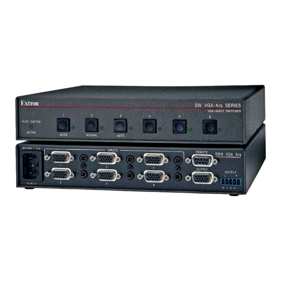
Page 10: Rear Panel Features And Connections
100-240V 0.2A REMOTE INPUTS SW6 VGA Ars SW2 VGA Ars the switcher, the number of connectors on the rear panel varies. Figure 2-3 shows the rear panels of the SW VGArs switchers. OUTPUT OUTPUT Figure 2-4 shows the rear panels of the SW VGA Ars switchers. -
Page 11: Audio (Sw Vga Ars) Models Only
Installation, cont’d Audio (SW VGA Ars) models only The length of exposed wires is critical. The ideal length is 3/16” (5 mm). — Plug a 3.5 mm stereo plug into this jack for unbalanced audio input. Wire the plug as •... -
Page 12: Identifying The Board Version And Setting The Sw Vga/Ars Jumpers
Installation, cont’d Identifying the Board Version and See the revision label on the board (figure 2-9), which list the board’s part number. Use this information to check Setting the SW VGA/Ars Jumpers compatibility with the VSW I AAP(s). If you plan to use the switcher with VSW I AAP remote If the board’s part number is not 20-1118-0n, this controls, you must configure the switcher. -
Page 13: Configuring The Switcher
Installation, cont’d Configuring the switcher SW VGArs / Ars Series Switchers There are six jumpers on the circuit board, numbered JMP5, JMP7, JMP9, JMP11, JMP 13, and JMP15, that control connection with one or more VSW I AAP control panels (figure 2-9 and figure 2-10). -
Page 14: Front Panel Controls And Indicators
Operation Front Panel Controls and Indicators — Use this button, with either the Auto or the Normal button, to manually turn auto switch mode on The front panels are identical for the non-audio or off. (SW VGArs) and audio (SW VGA Ars) models. Mode is a secondary function of the Input 1 button. -
Page 15: Selecting Auto Switch Mode
Operation cont d Selecting auto switch mode SW VGArs / Ars Series Switchers Press and hold the Input 1/Mode button while you press and release the Input 3/Auto button. The Auto Switch Active LED turns on, indicating auto switch mode. Release the Input 1/Mode button. -
Page 16: Host-To-Switcher Communications
The switcher-initiated messages are listed below: contact closure device. Other than the IR 102 Kit, remote communications with the switcher are via the Extron Simple (C) Copyright 2002, Extron Electronics SWy VGArs, Vx.xx ™ ® Instruction Set (SIS... -
Page 18: Command/Response Table For Sis Commands
Command/response table for SIS commands Command ASCII Command Response Additional description host to switcher switcher to host Input selection d o input Select input video and audio. d o input only & Select input video only (audio breakaway). d o input only Select input audio only (audio breakaway). - Page 19 Command/response table for SIS commands continued Command ASCII Command Response Additional description host to switcher switcher to host Front panel mode h mode Set switch mode to normal. h mode Set switch mode to auto (auto-switch). Front panel loc ecutive mode Lock front panel Exe1 Lock front panel controls.
-
Page 21: Using The Software
Using the software indicates that no video input signal is present. Run the program as follows: Click Start > Programs > Extron Electronics > Updating firmware Universal Switcher Control Pgm. If firmware updates are implemented for the SW VGA Ars, they Click the comm port that is connected to the are made available on the Extron Web site, www.extron.com. -
Page 22: Loading The Firmware To The Switcher
Remote Control, cont’d On the Download Center screen, click the SW VGA Series Loading the firmware to the switcher Download link. To load a new version of firmware to your SW VGA Ars switcher, call the Firmware Loader software from within the Universal Switcher Control Program. - Page 23 Remote Control, cont’d If you have not updated firmware for the SW VGA switcher Navigate to and select the new firmware file. The Choose before, on the Add Device screen, select the RS-232 tab. Firmware File window closes. If you have updated firmware for this model, click Cancel. When downloaded from the Extron Web site, the firmware The Firmware Loader window appears.
-
Page 24: Using The Help System
Contact closure control uses pins on the Remote connector that are not • Click Start > Programs > Extron Electronics > used by the RS-232 interface. The contact closure pin Universal Switcher Control Help. -
Page 25: Appendix A • Reference Information
Remote Control, cont’d SW VGArs / Ars Series Switchers A ppendix A Reference Information Specifications Part Numbers SW VGArs / Ars Series Switchers • Remote Control 4-16... - Page 26 Reference Information Output type ........RGBHV, RGBS, RGsB, RsGsBs, bi-level Specifications and tri-level sync (follows input) Input level ........1.0 V to 5.0 Vp-p Video Output level ........TTL: 5.0 Vp-p, unterminated Gain ..........Unity Input impedance ......510 ohms Bandwidth ........
-
Page 27: Switchers
(selected) when pin 5 Switcher Models Part number momentarily goes to gound. SW2 VGArs 60-257-02 Program control ......Extron’s control/configuration program SW2 VGA Ars 60-257-22 for Windows ® ™ Extron’s Simple Instruction Set (SIS SW4 VGArs 60-258-02...
Need help?
Do you have a question about the SW2 VGA Ars and is the answer not in the manual?
Questions and answers