
Related Manuals for KTI Networks KC-300DM Series


Summary of Contents for KTI Networks KC-300DM Series
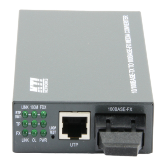
- Page 1 10/100BASE-TX TO 100BASE-FX MEDIA CONVERTERS KC-300DM Series Installation Guide DOC.220914...
- Page 2 KTI Networks Inc. KTI Networks Inc. reserves the right to revise this documentation and to make changes in content from time to time without obligation on the part of KTI Networks Inc. to provide notification of such revision or change.
- Page 3 The information contained in this document is subject to change without prior notice. Copyright (C) All Rights Reserved. TRADEMARKS Ethernet is a registered trademark of Xerox Corp. FCC NOTICE This device complies with Part 15 of the FCC Rules. Operation is subject to the following two conditions: (1) This device may not cause harmful interference, and (2) This device must accept any interference received, including the interference that may cause undesired operation.
-
Page 4: Table Of Contents
Table of Contents 1. Introduction ..........................5 1.1 Key Features ....................5 1.2 Specifications ....................6 1.3 Optical Specifications ..................9 1.4 Special Functions ................... 10 1.4.1 Auto MDI/MDI-X Function................10 1.4.2 Auto-negotiation Function................10 1.4.3 Far End Fault Function ................. 11 1.4.4 Link Fault Pass Through Function .............. -
Page 5: Introduction
1. Introduction The 10/100BASE-TX to 100BASE-FX media converter series provides a media conversion allowing high-speed integration of fiber optic and twisted-pair segments. With 10BASE-T and 100BASE-TX support, the converters provide seamless translation between Ethernet and Fast Ethernet networks. A complete set of LEDs allows for quick status verification. -
Page 6: Specifications
1.2 Specifications Twisted-Pair Interface (TPPort) Connector Shielded RJ-45 Pin Assignments Auto MDI/MDI-X detection Signal Compliance IEEE 802.3 10BASE-T, 802.3u 100BASE-TX Data Speed 10Mbps or 100Mbps Duplex Mode Half-duplex or Full-duplex Configuration Auto-negotiation capable and optional forced manual settings Cable Types 10Mbps - Category 3, 4, or 5 UTP 100Mbps - Category 5 UTP Supported Link Distance Up to 100 meters... - Page 7 RELEASE Stop loop back test User Accessible Settings (SW) NO. SETTING STATE FUNCTION SW1 TP Port Configuration Auto-negotiation (default)\ Forced mode SW2 TP Port Duplex Full duplex (default) Half duplex\ SW3 TP Port Speed 100Mbps (default) 10Mbps SW4 Link Fault Pass Through OFF Disable (default) Enable SW5 Auto-status-report...
- Page 8 Blink Collisions on half duplex FXLINK FX port link status Link up and no traffic Link fault Blink Rx/Tx activities FXOL FX port optical link ON Optical signal is detected No optical signal RTPLINK Remote TP port link ON Link up and no traffic Link fault RTP 100M Remote TP port speed ON 100Mbps...
-
Page 9: Optical Specifications
Packet Types Transparent and no modification for IEEE 802.3 standard packets IEEE 802.1Q VLAN tagged packets Packet Length Up to 1522 bytes at store-and-forward mode No limit at smart-forward mode (100to100) Flow Control Back-pressure for half-duplex mode 802.3x pause-frame base for full duplex mode Mechanical Dimension H 23mm x W 72.5mm x D 108mm... -
Page 10: Special Functions
300DM-SL6 1310nm -5 ~ 0dBm -35dBm 300DM-SL7 1310nm -3 ~ +3dBm -37dBm 300DM-SL9 1310nm 0 ~ +5dBm -37dBm 300DM-SL10 SC 1550nm -3 ~ +3dBm -37dBm 300DM-SL12 SC 1550nm 0 ~ +5dBm -37dBm Single Fiber Bi-Di WDM Series Model Port Fiber Wavelength Tx Power Rx Sensitivity... -
Page 11: Far End Fault Function
1.4.3 Far End Fault Function The FX port is facilitated with this function, which conforms to IEEE 802.3u 100BASE-FX specifications. When the FX port detects a link failure on its receiving circuitry, it will send out an FEFI (Far End Fault Indication) signal to the remote connected device to indicate a remote fault is detected. -
Page 12: Loop Back Test Function
periodical status report. 1.4.6 Loop Back Test Function As illustrated in the following figure, the local MC starts a loop back test by pressing the loop back test button. It sends test frames from its FX port to the remote MC. The remote MC forwards the received test frames back to local MC from its FX port. -
Page 13: Installation
2. Installation 2.1 Unpacking Check that the following components have been included: Installation guide (or contained in the product CD) 10/100 Media Converter One AC power adapter If any item is found missing or damaged, please contact your local reseller for replacement. 2.2 Mounting the Device Desktop Mounting The media converter can be mounted on a desktop or shelf. -
Page 14: Making Tp Port Connection
Rated AC120V/60Hz DC7.5V0.5Amin. Rated AC230V/50Hz DC7.5V0.5Amin. Rated AC240V/50Hz DC7.5V0.5Amin. Rated AC100V/50-60Hz DC7.5V0.5Amin. Rated AC100V/50-60Hz DC5V1A Steps to apply the power to the converters are: Connect power adapter DC plug to the DC input jack located on the back of the converter before connecting to the AC outlet. -
Page 15: Making Fx Port Connection
Fixed 100M full duplex device On: forced Off: full duplex Off: 100M 2.5 Making FX Port Connection FX port operates on 100Mbps and full duplex (factory default). A variety of fiber options is provided as follows: Duplex Fiber Series Model Connector Wavelength Fiber Ref. -
Page 16: Led Indicators
Rx 1310nm 300DM-W3540 Bi-Di SC Tx 1310nm Single SMF 40km Rx 1550nm 300DM-W5340 Bi-Di SC Tx 1550nm Single SMF 40km Rx 1310nm Since the WDM single fiber media converters use different wavelengths for transmission and receiving respectively, the link partner device located on the remote end of the single fiber should match the wavelength used on the single fiber converter. -
Page 17: Performing Loop Back Test
Remote TP port monitoring Display Status Interpretation RTP LINK Remote TP port link Link up and no traffic Link fault RTP 100M Remote TP port speed 100Mbps 10Mbps RTP FDX Remote TP port duplex On Full duplex Half duplex 2.7 Performing Loop Back Test To perform a loop back test between a local MC and a remote MC connected by a fiber cable, the steps are: 1. -
Page 18: Optional Configuration Settings
3. Optional Configuration Settings The media converter provides additional configuration settings which are user-inaccessible. The settings are built on the board inside the prod-uct case. The settings are provided for technical installers to adapt the converter to fit some specific application needs. 3.1 User Inaccessible Jumpers The setting jumpers are not accessible by users generally. -
Page 19: 802.3X Function Setting Jp2
without storing the received packet on one port then forwarding to another port. The media converter operates with the minimum latency. Note: In direct conversion, be sure both devices connected to the TP port and FX port have same duplex mode for proper transmission.
Need help?
Do you have a question about the KC-300DM Series and is the answer not in the manual?
Questions and answers