Sign In
Upload
Manuals
Brands
Advantech Manuals
Computer Hardware
PCA-6751 Series
Advantech PCA-6751 Series Manuals
Manuals and User Guides for Advantech PCA-6751 Series. We have
4
Advantech PCA-6751 Series manuals available for free PDF download: User Manual, Manual, Startup Manual
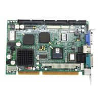
Advantech PCA-6751 Series User Manual (111 pages)
Half-size all-in-one Pentium CPU card with MMX CPU, VGA/LCD and Fast Ethernet interface
Brand:
Advantech
| Category:
Motherboard
| Size: 0 MB
Table of Contents
Copyright Notice
2
Optional Devices
3
Packing List
3
Table of Contents
4
Chapter 1 Hardware Configuration
10
Introduction
11
Embedded Pentium MMX CPU
11
Guaranteed Long Product Supply Time
11
Specifications
12
Standard SBC Functions
12
VGA Function
12
Ethernet Controller Functions (PCA-6751 Only)
13
Solid State Disk
13
Mechanic and Environmental Specifications
13
PCA-6751 Series' Models Comparison Table
13
Board Layout: Dimensions
14
Figure 1-1: PCA-6751 Series Board Layout: Dimensions
14
Safety Precautions
15
Jumper Settings
16
Introduction
16
Locating Jumpers
17
Table 1-1: Jumpers
17
COM2 Settings for RS-232/422/485 (JP1)
18
LCD Panel Select (JP2)
18
Table 1-2: COM2 Settings for RS-232/422/485 (JP1)
18
Table 1-3: LCD Panel Select (JP2)
19
CMOS Backup Select (JP3)
20
Table 1-4: RTC Power and CMOS Clear (JP3)
20
Watchdog Timer Configuration (JP4)
21
Table 1-5: Watchdog Timer System Reset Select (JP4)
21
Installing System Memory (Sodimms)
22
Installing Sodimms
22
Chapter 2 Connecting Peripherals
24
Board Layout: Connector Locations (Component Side)
25
Board Layout: Connector Locations (Solder Side)
26
Table 2-1: Connectors
27
FDD Connector (CN1)
28
Parallel Port Connector (CN2)
29
Keyboard Lock, LED Connector (CN3)
29
USB Connector (CN4)
29
24-Bit LCD Display Connector (CN5)
30
36-Bit LCD Display Connector (CN6)
30
LCD Inverter Connector (CN7)
30
IR Connector (CN8)
30
External Speaker Connector (CN9)
30
VGA Display Connector (CN11)
31
PC/104 Connectors (CN12)
31
Ethernet Connector (CN13) (PCA-6751 Only)
31
RJ-45A Connector (CN13)
31
Network Boot
31
Serial Ports (CN16: COM1; CN15: COM2/RS-232; CN14: COM2/RS-422/485)
32
Connection (COM1: CN16)
32
Table 2-2: Serial Port Connections (COM1, COM2)
32
Rs-232 Connection (Com1: Cn)
32
RS-232/422/485 Connection (COM2: CN15: RS-232; CN14: RS-422/485)
33
External Keyboard Connector (CN17)
33
ATX Power Connector (CN18)
33
Table 2-3: Serial Port Default Settings
33
AT Power Connector (CN20)
34
Keyboard and PS/2 Mouse Connector (CN21)
34
ISA Gold Fingers (CN22, CN23)
34
Compactflash™ Disk (CN24)
34
Front Panel Connector (CN25, CN26, CN27)
35
Hard Disk Drive LED (CN25)
35
Reset Switch (CN26)
35
ATX Power Button (CN27)
35
Enhanced IDE Connector (CN28)
36
ATX Feature Connector (CN27)
37
Chapter 3 Award BIOS Setup
38
Introduction
39
Entering Setup
39
Figure 3-1: Setup Program Initial Screen
39
Standard CMOS Setup
40
Figure 3-2: CMOS Setup Screen
40
BIOS Features Setup
41
Figure 3-3: BIOS Features Setup Screen
41
Chipset Features Setup
45
Figure 3-4: Chipset Features Setup Screen
45
Power Management Setup
46
Figure 3-5: Power Management Setup Screen
46
Pnp PCI Configuration Setup
47
Load BIOS Defaults
47
Load Setup Defaults
47
Figure 3-6: PCI Configuration Screen
47
Integrated Peripherals
48
Password Setting
48
Figure 3-7: Integrated Peripherals
48
IDE HDD Auto Detection
49
Save & Exit Setup
49
Exit Without Saving
49
Chapter 4 PCI SVGA Setup
50
Introduction
51
Chipset
51
Display Memory
51
Display Types
51
Installation of SVGA Driver
52
Installation for Windows 3.1
53
Installation for Windows 95
55
Installation for Windows NT
58
Further Information
61
Chapter 5 PCI Bus Ethernet Interface with Intel SB82558/SB82559 (PCA-6751 Only)
62
Introduction
63
Installation of Ethernet Driver
63
Installation for MS-DOS and Windows 3.1
63
Installation for Windows 95
64
Installation for Windows NT
66
Further Information
68
Chapter 6 PCI Bus Ethernet Interface with RTL-8139 (PCA-6751 Only)
70
Introduction
71
Installation of Ethernet Driver
71
Installation for MS-DOS and Windows 3.1
71
Installation for Windows 95/98
72
Installation for Windows NT
74
Further Information
76
Appendix A Programming the Watchdog Timer
78
Programming the Watchdog Timer
79
Appendix B Installing PC/104 Modules
82
Installing PC/104 Modules
83
Figure B-1: PC/104 Module Mounting Diagram
84
Figure B-2: PC/104 Module Dimensions (MM) (±0.1)
84
Table B-1: PCA-6751 Series PC/104 Connectors (CN12)
85
Appendix C Pin Assignments
86
Floppy Drive Connector (CN1)
87
Table C-1: Floppy Drive Connector (CN1)
87
Parallel Port Connector (CN2)
88
Table C-2: Parallel Port Connector (CN2)
88
Keyboard Lock, LED Connector (CN3)
89
USB1/USB2 Connector (CN4)
89
Table C-3: Keyboard Lock, LED Connector (CN3)
89
Table C-4: USB1/USB2 Connector (CN4)
89
24-Bit LCD Display Connector (CN5)
90
Table C-5: 24-Bit LCD Display Connector (CN5)
90
36-Bit LCD Display Connector (CN6)
91
Table C-6: 36-Bit LCD Display Connector (CN6)
91
LCD Inverter Connector (CN7)
92
IR Connector (CN8)
92
Table C-7: LCD Inverter Connector (CN7)
92
Table C-8: IR Connector (CN8)
92
External Speaker Connector (CN9)
93
VGA Connector (CN11)
93
Table C-9: External Speaker Connector (CN9)
93
Table C-10: VGA Connector (CN11)
93
PC/104 Connector (CN12)
94
Ethernet Connector (CN13)
94
Table C-11: Ethernet Connector (CN1)
94
C.12 Ethernet Connector (Cn)
94
COM2 RS-422/485 Connector (CN14)
95
Table C-12: COM2 RS-232/422/485 Connector (CN14)
95
COM2 RS-232 Connector (CN15)
96
Table C-13: COM2 RS-232 Connector (CN15)
96
COM1 RS-232 Connector (CN16)
97
External Keyboard Connector (CN17)
97
Table C-14: COM1 RS-232 Connector (CN16)
97
Table C-15: External Keyboard Connector (CN17)
97
C.16 External Keyboard Connector (Cn)
97
AT Power Connector (CN20)
98
ATX Power Connector (CN18)
98
Table C-16: ATX Power Connector (CN18)
98
Table C-17: at Power Connector (CN20)
98
C.18 at Power Connector (Cn)
98
Keyboard and PS/2 Mouse Connector (CN21)
99
Table C-18: Keyboard and PS/2 Mouse Connector (CN21)
99
Compactflash™ Card Connector (CN24)
100
Table C-19: Compactflash™ Card Connector (CN24)
100
C.20 Compactflash™ Card Connector (Cn)
100
ATX Power Button (CN27)
101
HDD LED Connector (CN25)
101
System Reset Switch Connector (CN26)
101
Table C-20: HDD LED Connector (CN25)
101
Table C-21: System Reset Switch Connector (CN26)
101
Table C-22: ATX Power Button (CN27)
101
C.22 System Reset Switch Connector (Cn)
101
C.23 Atx Power Button (Cn)
101
Enhanced IDE Connector (CN28)
102
Table C-23: Enhanced IDE Connector (CN28)
102
Appendix D System Assignments
104
System I/O Ports
105
Table D-1: System I/O Ports
105
DMA Channel Assignments
106
Table D-2: DMA Channel Assignments
106
Interrupt Assignments
107
Table D-3: Interrupt Assignments
107
1St MB Memory Map
108
Table D-4: 1St MB Memory Map
108
Appendix E LCD Services
110
LCD Services
111
E.1 LCD Services
111
Advertisement
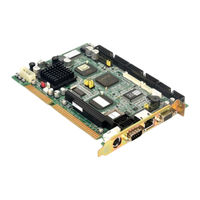
Advantech PCA-6751 Series User Manual (113 pages)
Half-size all-in-one Pentium CPU card with MMX CPU, VGA/LCD and Fast Ethernet interface
Brand:
Advantech
| Category:
Computer Hardware
| Size: 22 MB
Table of Contents
Copyright Notice
3
Optional Devices
4
Packing List
4
Table of Contents
5
Chapter 1 Hardware Configuration
11
Introduction
12
Embedded Pentium MMX CPU
12
Guaranteed Long Product Supply Time
12
Specifications
13
Standard SBC Functions
13
VGA Function
13
Ethernet Controller Functions (PCA-6751 Only)
14
Solid State Disk
14
Mechanic and Environmental Specifications
14
PCA-6751 Series' Models Comparison Table
14
Board Layout: Dimensions
15
Figure 1-1: PCA-6751 Series Board Layout: Dimensions
15
Safety Precautions
16
Jumper Settings
17
Introduction
17
Locating Jumpers
18
Table 1-1: Jumpers
18
COM2 Settings for RS-232/422/485 (JP1)
19
LCD Panel Select (JP2)
19
Table 1-2: COM2 Settings for RS-232/422/485 (JP1)
19
Table 1-3: LCD Panel Select (JP2)
20
CMOS Backup Select (JP3)
21
Table 1-4: RTC Power and CMOS Clear (JP3)
21
Watchdog Timer Configuration (JP4)
22
Table 1-5: Watchdog Timer System Reset Select (JP4)
22
Installing System Memory (Sodimms)
23
Installing Sodimms
23
Chapter 2 Connecting Peripherals
25
Board Layout: Connector Locations (Component Side)
26
Board Layout: Connector Locations (Solder Side)
27
Table 2-1: Connectors
28
FDD Connector (CN1)
29
Parallel Port Connector (CN2)
30
Keyboard Lock, LED Connector (CN3)
30
USB Connector (CN4)
30
24-Bit LCD Display Connector (CN5)
31
36-Bit LCD Display Connector (CN6)
31
LCD Inverter Connector (CN7)
31
IR Connector (CN8)
31
External Speaker Connector (CN9)
31
VGA Display Connector (CN11)
32
PC/104 Connectors (CN12)
32
Ethernet Connector (CN13) (PCA-6751 Only)
32
RJ-45A Connector (CN13)
32
Network Boot
32
Serial Ports (CN16: COM1; CN15: COM2/RS-232; CN14: COM2/RS-422/485)
33
Connection (COM1: CN16)
33
Table 2-2: Serial Port Connections (COM1, COM2)
33
RS-232/422/485 Connection (COM2: CN15: RS-232; CN14: RS-422/485)
34
External Keyboard Connector (CN17)
34
ATX Power Connector (CN18)
34
Table 2-3: Serial Port Default Settings
34
AT Power Connector (CN20)
35
Keyboard and PS/2 Mouse Connector (CN21)
35
ISA Gold Fingers (CN22, CN23)
35
Compactflash™ Disk (CN24)
35
Front Panel Connector (CN25, CN26, CN27)
36
Hard Disk Drive LED (CN25)
36
Reset Switch (CN26)
36
ATX Power Button (CN27)
36
Enhanced IDE Connector (CN28)
37
ATX Feature Connector (CN27)
38
Chapter 3 Award BIOS Setup
39
Introduction
40
Entering Setup
40
Figure 3-1: Setup Program Initial Screen
40
Standard CMOS Setup
41
Figure 3-2: CMOS Setup Screen
41
BIOS Features Setup
42
Figure 3-3: BIOS Features Setup Screen
42
Chipset Features Setup
46
Figure 3-4: Chipset Features Setup Screen
46
Power Management Setup
47
Figure 3-5: Power Management Setup Screen
47
Pnp PCI Configuration Setup
48
Load BIOS Defaults
48
Load Setup Defaults
48
Figure 3-6: PCI Configuration Screen
48
Integrated Peripherals
49
Password Setting
49
Figure 3-7: Integrated Peripherals
49
IDE HDD Auto Detection
50
Save & Exit Setup
50
Exit Without Saving
50
Chapter 4 PCI SVGA Setup
51
Introduction
52
Chipset
52
Display Memory
52
Display Types
52
Installation of SVGA Driver
53
Installation for Windows 3.1
54
Installation for Windows 95
56
Installation for Windows NT
59
Further Information
62
Chapter 5 PCI Bus Ethernet Interface with Intel SB82558/SB82559 (PCA-6751 Only)
63
Introduction
64
Installation of Ethernet Driver
64
Installation for MS-DOS and Windows 3.1
64
Installation for Windows 95
65
Installation for Windows NT
67
Further Information
69
Chapter 6 PCI Bus Ethernet Interface with RTL-8139 (PCA-6751 Only)
71
Introduction
72
Installation of Ethernet Driver
72
Installation for MS-DOS and Windows 3.1
72
Installation for Windows 95/98
73
Installation for Windows NT
75
Further Information
77
Appendix A Programming the Watchdog Timer
79
Programming the Watchdog Timer
80
Appendix B Installing PC/104 Modules
83
Installing PC/104 Modules
84
Figure B-1: PC/104 Module Mounting Diagram
85
Figure B-2: PC/104 Module Dimensions (MM) (±0.1)
85
Table B-1: PCA-6751 Series PC/104 Connectors (CN12)
86
Appendix C Pin Assignments
87
Floppy Drive Connector (CN1)
88
Table C-1: Floppy Drive Connector (CN1)
88
Parallel Port Connector (CN2)
89
Table C-2: Parallel Port Connector (CN2)
89
Keyboard Lock, LED Connector (CN3)
90
USB1/USB2 Connector (CN4)
90
Table C-3: Keyboard Lock, LED Connector (CN3)
90
Table C-4: USB1/USB2 Connector (CN4)
90
24-Bit LCD Display Connector (CN5)
91
Table C-5: 24-Bit LCD Display Connector (CN5)
91
36-Bit LCD Display Connector (CN6)
92
Table C-6: 36-Bit LCD Display Connector (CN6)
92
LCD Inverter Connector (CN7)
93
IR Connector (CN8)
93
Table C-7: LCD Inverter Connector (CN7)
93
Table C-8: IR Connector (CN8)
93
External Speaker Connector (CN9)
94
VGA Connector (CN11)
94
Table C-9: External Speaker Connector (CN9)
94
Table C-10: VGA Connector (CN11)
94
PC/104 Connector (CN12)
95
Ethernet Connector (CN13)
95
Table C-11: Ethernet Connector (CN1)
95
COM2 RS-422/485 Connector (CN14)
96
Table C-12: COM2 RS-232/422/485 Connector (CN14)
96
COM2 RS-232 Connector (CN15)
97
Table C-13: COM2 RS-232 Connector (CN15)
97
COM1 RS-232 Connector (CN16)
98
External Keyboard Connector (CN17)
98
Table C-14: COM1 RS-232 Connector (CN16)
98
Table C-15: External Keyboard Connector (CN17)
98
ATX Power Connector (CN18)
99
AT Power Connector (CN20)
99
Table C-16: ATX Power Connector (CN18)
99
Table C-17: at Power Connector (CN20)
99
Keyboard and PS/2 Mouse Connector (CN21)
100
Table C-18: Keyboard and PS/2 Mouse Connector (CN21)
100
Compactflash™ Card Connector (CN24)
101
Table C-19: Compactflash™ Card Connector (CN24)
101
HDD LED Connector (CN25)
102
System Reset Switch Connector (CN26)
102
ATX Power Button (CN27)
102
Table C-20: HDD LED Connector (CN25)
102
Table C-21: System Reset Switch Connector (CN26)
102
Table C-22: ATX Power Button (CN27)
102
Enhanced IDE Connector (CN28)
103
Table C-23: Enhanced IDE Connector (CN28)
103
Appendix D System Assignments
105
System I/O Ports
106
Table D-1: System I/O Ports
106
DMA Channel Assignments
107
Table D-2: DMA Channel Assignments
107
Interrupt Assignments
108
Table D-3: Interrupt Assignments
108
1St MB Memory Map
109
Table D-4: 1St MB Memory Map
109
Appendix E LCD Services
111
LCD Services
112
Advantech PCA-6751 Series Manual (102 pages)
half-size all-in-one Pentium CPU card with MMX CPU VGA/LCD and fast ethernet interface
Brand:
Advantech
| Category:
Computer Hardware
| Size: 1 MB
Table of Contents
Copyright Notice
2
Optional Devices
3
Packing List
3
Table of Contents
4
Chapter 1 Hardware Configuration
11
Introduction
12
Embedded Pentium
12
MMX Cpu
12
Guaranteed Long Product Supply Time
12
Specifications
13
Standard SBC Functions
13
VGA Function
13
Ethernet Controller Functions (PCA-6751 Only)
14
Solid State Disk
14
Mechanic and Environmental Specifications
14
Board Layout: Dimensions
15
Figure 1-1: Board Layout: Dimensions
15
Safety Precautions
16
Jumper Settings
17
COM2 Settings for RS-232/422/485 (JP1)
18
LCD Panel Select (JP2)
18
Table 1-1: COM2 Settings for RS-232/422/485 (JP1)
18
Table 1-2: LCD Panel Select (JP2)
19
CMOS Backup Select (JP3)
20
Table 1-3: RTC Power and CMOS Clear (JP3)
20
Watchdog Timer Configuration (JP4)
21
Table 1-4: Watchdog Timer System Reset Select (JP4)
21
Installing System Memory (Sodimms)
22
Installing Sodimms
22
Chapter 2 Connecting Peripherals
23
Board Layout: Connector Locations (Component Side)
24
Board Layout: Connector Locations (Solder Side)
25
Table 2-1: Connectors
26
Floppy Drive Connector (CN1)
27
Parallel Port Connector (CN2)
28
Keyboard Lock (CN3)
28
USB Connector (CN4)
28
24-Bit LCD Display Connector (CN5)
29
36-Bit LCD Display Connector (CN6)
29
LCD Inverter Connector (CN7)
29
IR Connector (CN8)
29
External Speaker (CN9)
29
Watchdog Timer PROG (CN10)
30
VGA Display Connector (CN11)
30
Connectors (CN12)
30
Ethernet Configuration (CN13 PCA-6751 Only)
30
RJ-45A Connector (CN13)
30
Network Boot
30
Serial Ports (CN16: COM1; CN15: COM2/RS-232; CN14: COM2/RS-422/485)
31
Table 2-2: Serial Port Connections (COM1, COM2)
31
External Keyboard (CN17)
32
ATX Power Connector (CN18)
32
Table 2-3: Serial Port Default Settings
32
CPU Fan Power Supply Connector (CN19)
33
AT Power Ponnector (CN20)
33
Keyboard & PS/2 Mouse Connector (CN21)
33
ISA Goldfinger (CN22, 23)
33
Compactflash Disk (CN24)
34
Front Panel Connector (CN25, 26, 27)
34
Hard Disk Drive LED (CN25)
34
Reset Switch (CN26)
34
ATX Power Button (CN27)
34
Enhanced IDE Connector (CN28)
35
Chapter 3 Award BIOS Setup
37
Award BIOS Setup
38
Entering Setup
38
Figure 3-1: Setup Program Initial Screen
38
Standard CMOS Setup
39
Figure 3-2: CMOS Setup Screen
39
BIOS Features Setup
40
Figure 3-3: BIOS Features Setup Screen
40
Chipset Features Setup
44
Figure 3-4: CHIPSET Features Setup Screen
44
Power Management Setup
45
Figure 3-5: Power Management Setup Screen
45
Pnp PCI Configuration Setup
46
Load BIOS Defaults
46
Load Setup Defaults
46
Figure 3-6: PCI Configuration Screen
46
Integrated Peripherals
47
Password Setting
47
Figure 3-7: Integrated Peripherals
47
IDE HDD Auto Detection
48
Save & Exit Setup
48
Exit Without Saving
48
Chapter 4 PCI SVGA Setup
49
Introduction
50
Chipset
50
Display Memory
50
Installation of SVGA Driver
51
Installation for Windows 3.1
52
Installation for Windows 95
54
Installation for Windows NT
57
Further Information
60
Chapter 5 PCI Bus Ethernet Interface (PCA-6751 Only)
61
Introduction
62
Installation of Ethernet Driver
62
Installation for MS-DOS & Windows 3.1
62
Installation for Windows 95
63
Installation for Windows NT
65
Further Information
67
Appendix A Programming the Watchdog Timer
69
A.1 Programming the Watchdog Timer
70
Appendix B Installing PC/104 Modules
73
B.1 Installing PC/104 Modules
74
Figure B-1: PC/104 Module Mounting Diagram
75
Figure B-2: PC/104 Module Dimensions (MM) (±0.1)
75
Table B-1: PC/104 Connectors (CN12)
76
Pin Assignments
77
Table C-1: Floppy Drive Connector
78
Table C-2: Parallel Port Connector
79
Table C-3: Keyboard Lock Connector
80
Table C-4: USB1/USB2 Connector
80
Table C-5: 24-Bit LCD Display Connector
81
Table C-6: 36-Bit LCD Display Connector
82
Table C-7: LCD Power Inverter
82
Table C-8: IR Connector
83
Table C-9: External Speaker Connector
83
Table C-10: CRT Display Connector
84
Table C-11: COM2 RS-232/422/485 Series Port
84
Table C-12: COM2 RS-232 Serial Port
85
Table C-13: COM1 RS-232 Serial Port
85
Table C-14: External Keyboard Connector
86
Table C-15: ATX Power Connector
86
Table C-16: CPU Fan Power Connector
87
Table C-17: at Power Connector
87
Table C-18: Keyboard and Mouse Connector
88
Appendix C Pin Assignments
88
C.18 Keyboard and Mouse Connnector (CN21)
88
Table C-19: Compactflash Card Connector
89
Table C-20: HDD LED Connector
90
Table C-21: Reset Switch Connector
90
C.23 IDE Hard Drive Connector (CN28)
91
System Assignments
93
Table D-1: System I/O Ports
94
Table D-2: DMA Channel Assignments
95
Table D-3: Interrupt Assignments
95
Table D-4:1St MB Memory Map
96
Lcd Services
97
E.1 LCD Services
98
Model Number
99
Advertisement
Advantech PCA-6751 Series Startup Manual (4 pages)
Pentium MMX CPU card with VGA/LCD and Fast Ethernet
Brand:
Advantech
| Category:
Motherboard
| Size: 0 MB
Table of Contents
Packing List
1
Specifications
1
Standard SBC Functions
1
VGA Function
1
Ethernet Controller Functions (PCA-6751 Only)
1
Solid State Disk
1
Jumpers and Connectors
2
Jumper Settings
2
Mechanical and Environmental
2
Mechanical Drawings
3
Locating Jumpers
3
Locating Connectors (Component Side)
3
Board Dimensions
4
Locating Connectors (Solder Side)
4
Advertisement
Related Products
Advantech PCA-6742 Series
Advantech PCA-6740
Advantech PCA-6751V
Advantech PCA-6751L
Advantech PCA-6751-F0B1
Advantech PCA-6751-F0A1
Advantech PCA-6751-A0A1
Advantech PCA-6751-F1B1
Advantech PCA-6751L-F0B1
Advantech PCA-6186VE-00A1
Advantech Categories
Motherboard
Computer Hardware
Desktop
Touch Panel
Network Router
More Advantech Manuals
Login
Sign In
OR
Sign in with Facebook
Sign in with Google
Upload manual
Upload from disk
Upload from URL