
Related Manuals for Banner DF-G3 Long Range Expert


Summary of Contents for Banner DF-G3 Long Range Expert
- Page 1 ™ DF-G3 Long Range Expert Dual Display Fiber Amplifier Instruction Manual Original Instructions 187436 Rev. F 21 April 2017 © Banner Engineering Corp. All rights reserved 187436...
-
Page 2: Table Of Contents
4.1 Excess Gain Curves ....................................28 4.2 Beam Patterns ...................................... 30 4.3 Dimensions ......................................33 5 Accessories ..................................34 5.1 Quick-Disconnect Cordsets—Single Output Models ........................... 34 5.2 Quick-Disconnect Cordsets—Dual Output Models ..........................35 5.3 Banner Engineering Corp. Limited Warranty ............................36... -
Page 3: Product Description
™ DF-G3 Long Range Expert Dual Display Fiber Amplifier 1 Product Description Advanced sensor with dual digital displays for use with plastic and glass fiber optic assemblies; single or dual discrete output models are available. • World-class long-range sensing capability, more than 6 m (20 ft) with opposed mode fibers •... -
Page 4: Overview
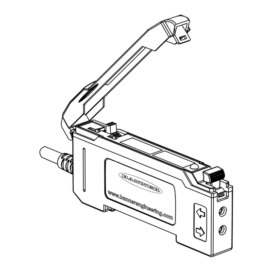
™ DF-G3 Long Range Expert Dual Display Fiber Amplifier 1.2 Overview Single Output LED or Dual Output LEDs LO/DO Switch (Single Output) or CH1/CH2 Switch (Dual Output) RUN/PRG/ADJ Mode Switch Figure 1. DF-G3 Single Output Lever Action Fiber Clamp Red Signal Level... - Page 5 ™ DF-G3 Long Range Expert Dual Display Fiber Amplifier Single Output LED The output LED provides a visible indication when the output is activated. Dual Output LEDs The output LEDs provide a visible indication when the associated output is active.
-
Page 6: Installation Instructions
™ DF-G3 Long Range Expert Dual Display Fiber Amplifier 2 Installation Instructions 2.1 Mounting Instructions Mount on a DIN Rail 1. Hook the DIN rail clip on the bottom of the DF-G3 over the edge of the DIN rail (1). -
Page 7: Fiber Adapters
Note: If a thin fiber with less than 2.2 mm outer diameter is used, install the fiber adapter provided with the fiber assembly to ensure a reliable fit in the fiber holder. Align the fibers to the end of the adaptors. Banner includes the adapters with all fiber assemblies. - Page 8 ™ DF-G3 Long Range Expert Dual Display Fiber Amplifier Dual Output NPN Models PNP Models 1 = Brown 2 = White – 3 = Blue 10–30 V dc 10–30 V dc 4 = Black – 5 = Gray (6 = no connection)
-
Page 9: Operating Instructions
™ DF-G3 Long Range Expert Dual Display Fiber Amplifier 3 Operating Instructions 3.1 Run Mode Run mode allows the sensor to operate normally and prevents unintentional programming changes. The +/SET/- rocker button is disabled during RUN mode, except when using Window SET. -
Page 10: Program Mode
™ DF-G3 Long Range Expert Dual Display Fiber Amplifier 3.2 Program Mode Channel 1 Menu Program (PRG) mode allows the following settings to be programmed in the DF-G3. CH1 Factory Default Settings: Out SEL1 (dual only) tch SEL1 2-pt tch... -
Page 11: Output Selection
™ DF-G3 Long Range Expert Dual Display Fiber Amplifier Channel 2 Menu Program (PRG) mode allows the following settings to be programmed in the DF-G3. The LO/DO switch is replaced with the CH1/CH2 selection switch. LO/DO is selected via the Program Mode menu. -
Page 12: Teach Selection
™ DF-G3 Long Range Expert Dual Display Fiber Amplifier 3. If the fiber optic array is contaminated enough that the auto compensation tracking algorithm cannot sufficiently adjust the thresholds to ensure reliable detection 4. If the fiber optic array is blocked for more than 2 seconds... -
Page 13: Delays/Timers
™ DF-G3 Long Range Expert Dual Display Fiber Amplifier 3.2.6 Delays/Timers ON/OFF Delays and ON/OFF One-Shot timers can be programmed independently for both CH1 Output and CH2 for a time period between between 1 - 9999 ms (a value of 0 disables the delay/timer). -
Page 14: Gain Selection
™ DF-G3 Long Range Expert Dual Display Fiber Amplifier 3.2.10 Gain Selection The DF-G3 can operate in Auto Gain mode or the Gain can be fixed to be in Gain 1...7. In Auto Gain, the DF-G3 optimizes the gain during a TEACH/SET method for the presented condition(s). -
Page 15: Sync Master/Slave
3.4 Sync Master/Slave Up to seven DF-G3 Long Range Expert Dual Display Fiber Amplifier sensors may be used together in a single sensing application. To eliminate crosstalk between the sensors, configure one sensor to be the master and the remaining sensors to be the slaves. In this mode, the sensors alternate taking measurements and the response speed is 2 ms. -
Page 16: Adjust Mode
™ DF-G3 Long Range Expert Dual Display Fiber Amplifier 1. Configure the first sensor as the Master (inPt SEL = MAST). 2. In the Master sensor set-up, enter the total number of Slave sensors you will be using (tOtL SLAV = 1 - 6). -
Page 17: Dynamic Teach
™ DF-G3 Long Range Expert Dual Display Fiber Amplifier Method Action Result SET Button 5 Set the Mode switch to ADJ. Display: Red - Signal Level; Green - Threshold Remote Input 6 No action is required; sensor is ready for the Two-Point TEACH method 2. - Page 18 ™ DF-G3 Long Range Expert Dual Display Fiber Amplifier Darkest Taught Lightest Taught Condition Condition Sensor positions threshold midway between taught conditions Output OFF Output ON Darkest Position Most Light (no signal) adjusted by (saturated Manual Adjust signal) Figure 7. Dynamic TEACH (Light Operate shown) The Output ON and OFF conditions can be reversed by using the LO/DO (Light Operate/ Dark Operate) switch or through the program interface for the dual output model.
-
Page 19: Window Set
™ DF-G3 Long Range Expert Dual Display Fiber Amplifier 4. Exit Dynamic TEACH. Method Action Result SET Button Click the SET rocker button TEACH Accepted Displays alternate "PASS" with % Minimum Difference 10 , Sensor returns to Adjust mode Remote Input... - Page 20 ™ DF-G3 Long Range Expert Dual Display Fiber Amplifier Remember: Manual adjustments are disabled when Auto Thresholds are ON Follow these steps to perform a Window SET: Note: TEACH Selection must be programmed to wind SEt. 1. Enter Adjust Mode...
-
Page 21: Light Set
™ DF-G3 Long Range Expert Dual Display Fiber Amplifier 3.5.4 Light SET • Sets a threshold a programmable % offset below the presented condition • Changes output state on any condition darker than the threshold condition • Threshold can be adjusted using "+" and "-" rocker button (Manual Adjust) •... -
Page 22: Dark Set
™ DF-G3 Long Range Expert Dual Display Fiber Amplifier Method Action Result SET Button • Present sensing condition Threshold Condition Accepted Displays read "Lt SEt" then alternate "PASS" with % • Click the SET rocker button Offset 16 ; Sensor returns to Adjust mode Remote Input •... -
Page 23: Calibration Set
™ DF-G3 Long Range Expert Dual Display Fiber Amplifier Remember: Manual adjustments are disabled when Auto Thresholds are ON Follow these steps to perform a Dark SET: Note: TEACH Selection must be programmed to dr SEt. 1. Enter Adjust Mode. - Page 24 ™ DF-G3 Long Range Expert Dual Display Fiber Amplifier Threshold position adjusted by Manual Adjust Sensor positions threshold exactly at the presented condition Output OFF Output ON Condition Darkest Most Light Presented (no signal) (saturated signal) Figure 12. Calibration SET (Light Operate shown)
-
Page 25: Troubleshooting
™ DF-G3 Long Range Expert Dual Display Fiber Amplifier Method Action Result SET Button Move Mode switch to RUN Display: Red - Signal Level; Green - Threshold Remote Input No action required; sensor returns to RUN mode automatically 3.6 Troubleshooting 3.6.1 Manual Adjustments Disabled... -
Page 26: Specifications
™ DF-G3 Long Range Expert Dual Display Fiber Amplifier 4 Specifications Sensing Beam DF-G3: Visible red, 635 nm DF-G3IR: Infrared, 850 nm DF-G3LIR: Long infrared, 1450 nm Supply Voltage 10 V to 30 V dc Class 2 (10% maximum ripple) Power and Current Consumption (exclusive of load) Standard display mode: 840 mW, Current consumption <... - Page 27 ™ DF-G3 Long Range Expert Dual Display Fiber Amplifier Adjustments 3-way RUN/PRG/ADJ Mode Switch 2-way LO/DO Switch or CH1/CH2 Switch 3-way +/SET/- Rocker Button • Expert-style teaching (Two-Point and Dynamic TEACH, Light/Dark/Window/Calibration SET) • Manually adjust sensitivity (from "+" and "-" rocker button only) •...
-
Page 28: Excess Gain Curves
™ DF-G3 Long Range Expert Dual Display Fiber Amplifier Required Overcurrent Protection WARNING: Electrical connections must be made by qualified personnel in accordance with local and national electrical codes and regulations. Overcurrent protection is required to be provided by end product application per the supplied table. - Page 29 ™ DF-G3 Long Range Expert Dual Display Fiber Amplifier 1000000 10000000 24mS 24mS 1000000 100000 1&2mS 1&2mS 100000 500uS 500uS 10000 10000 1000 1000 1000 10000 1000 10000 Distance (mm) Distance (mm) Figure 15. Diffuse—PBT46U Figure 16. Diffuse—PBT66U 1000000 100000...
-
Page 30: Beam Patterns
™ DF-G3 Long Range Expert Dual Display Fiber Amplifier 100000 100000 24mS 24mS 10000 10000 1&2mS 1&2mS 500uS 500uS 1000 1000 1000 10000 1000 10000 Distance (mm) Distance (mm) Note: BTC1.13.4ST5M6 glass fiber used for diffuse mode Note: IT.83.3ST5M6 glass fiber used for opposed mode Figure 21. - Page 31 ™ DF-G3 Long Range Expert Dual Display Fiber Amplifier 24mS 24mS 250.0 200.0 1&2mS 1&2mS 150.0 500uS 500uS 100.0 50.0 -50.0 -100 -100.0 -150.0 -200 -200.0 -250.0 -300 1000 1200 1000 1500 2000 2500 Distance (mm) Distance (mm) Figure 27. Diffuse—PBT46U Figure 28.
- Page 32 ™ DF-G3 Long Range Expert Dual Display Fiber Amplifier 24mS 300.0 2000 24mS 2/1mS 1500 0.5mS 2/1mS 200.0 0.5mS 1000 100.0 -500 -100.0 -1000 -200.0 -1500 -300.0 -2000 1000 1500 2000 2500 1000 2000 3000 4000 5000 6000 7000 Distance (mm) Distance (mm) Note: BTC1.13.4ST5M6 glass fiber used for diffuse mode...
-
Page 33: Dimensions
™ DF-G3 Long Range Expert Dual Display Fiber Amplifier 4.3 Dimensions www.bannerengineering.com - Tel: 763.544.3164... -
Page 34: Accessories
™ DF-G3 Long Range Expert Dual Display Fiber Amplifier 5 Accessories DIN-35-.. SA-DIN-CLAMP • Pair of metal DIN rail end stops; slide onto DIN rail at either side 35 mm DIN Rail of the sensor stack • Combination (#2 Phillips, #8 standard slotted) set screw... -
Page 35: Quick-Disconnect Cordsets-Dual Output Models
™ DF-G3 Long Range Expert Dual Display Fiber Amplifier 4-Pin Threaded M8/Pico-Style Cordsets Model Length Style Dimensions Pinout (Female) PKG4M-2 2 m (6.56 ft) 35 Typ. PKG4M-5 5 m (16.4 ft) Straight ø 9.5 PKG4M-9 9 m (29.5 ft) M8 x 1 PKW4M-2 2 m (6.56 ft) -
Page 36: Banner Engineering Corp. Limited Warranty
MERCHANTABILITY OR FITNESS FOR A PARTICULAR PURPOSE), AND WHETHER ARISING UNDER COURSE OF PERFORMANCE, COURSE OF DEALING OR TRADE USAGE. This Warranty is exclusive and limited to repair or, at the discretion of Banner Engineering Corp., replacement. IN NO EVENT SHALL BANNER ENGINEERING CORP. BE LIABLE TO BUYER OR ANY OTHER PERSON OR ENTITY FOR ANY EXTRA COSTS, EXPENSES, LOSSES, LOSS OF PROFITS, OR ANY INCIDENTAL, CONSEQUENTIAL OR SPECIAL DAMAGES RESULTING FROM ANY PRODUCT DEFECT OR FROM THE USE OR INABILITY TO USE THE PRODUCT, WHETHER ARISING IN CONTRACT OR WARRANTY, STATUTE, TORT, STRICT LIABILITY, NEGLIGENCE, OR OTHERWISE.
Need help?
Do you have a question about the DF-G3 Long Range Expert and is the answer not in the manual?
Questions and answers